Table of Contents
Advertisement
Quick Links
Advertisement
Table of Contents

Subscribe to Our Youtube Channel
Related Manuals for Sierra Wireless AirPrime HL Development Kit


Summary of Contents for Sierra Wireless AirPrime HL Development Kit
- Page 1 Development Kit User Guide AirPrime HL Series 4114877 October 12, 2015...
- Page 2 Data may be delayed, corrupted (i.e., have errors) or be totally lost. Although significant delays or losses of data are rare when wireless devices such as the Sierra Wireless modem are used in a normal manner with a well-constructed network, the Sierra Wireless modem should not be used in situations where failure to transmit or receive data could result in damage of any kind to the user or any other party, including but not limited to personal injury, death, or loss of property.
- Page 3 This product may contain technology developed by or for Sierra Wireless Inc. ® This product includes technology licensed from QUALCOMM This product is manufactured or sold by Sierra Wireless Inc. or its affiliates under one or more patents licensed from InterDigital Group and MMP Portfolio Licensing. Copyright ©...
- Page 4 Development Kit User Guide Document History Version Date Updates November 21, 2013 Creation March 04, 2014 Added HL8548x support Updated: Board version number Table 3 Available Connections March 10, 2014 3.8 UART0/SPI1 Deleted obsolete connectors Added Snap-in socket information; updated information for board version 1400897-I December 12, 2014 Removed socket board information...
-
Page 5: Table Of Contents
Contents 1. OVERVIEW ......................9 2. GENERAL DESCRIPTION ................. 11 2.1. RoHS Compliance ......................11 2.2. Development Kit ......................12 2.2.1. Features ........................13 2.2.2. Connectors and Component Placement ..............13 2.2.3. Snap-In Connector ....................18 2.2.4. Test Ports ......................... 20 2.3. - Page 6 Development Kit User Guide 6. REFERENCE DOCUMENTS ................46 7. DEV-KIT SCHEMATIC DIAGRAMS ..............47 4114877 Rev 5.0 October 12, 2015...
- Page 7 List of Figures Figure 1. AirPrime HL Series Development Kit (board version 1400897-I) ........12 Figure 2. Available Connectors and Components on the AirPrime HL Series Development Kit ... 14 Figure 3. Snap-in Connector ......................18 Figure 4. Module Position for HL6528x (without label) ..............18 Figure 5.
- Page 8 List of Tables Table 1. Supported Module Variants ....................9 Table 2. Connector and Switch Description .................. 15 Table 3. Available Connections ..................... 16 Table 4. AirPrime HL Series Development Kit Test Ports ............. 20 Table 5. Audio Connector Pin Description ..................26 Table 6.
-
Page 9: Overview
1. Overview This document describes the AirPrime HL Series Development Kit (board version 1400897-I) and how it integrates with the AirPrime HL6528x, HL75xx and HL85xxx series of embedded modules via a specific Snap-in connector. It also briefly describes the different interfaces and peripheral connections supported by the HL Series Development Kit and provide schematics to facilitate the user’s understanding and configuration of the development kit board for their own application use. - Page 10 Development Kit User Guide Overview Series Variant Part Number Description HL8518 1600676 1.8V; GSM/GPRS/UMTS (B1, B8) capable 1.8V; GSM/GPRS/EDGE GSM 850/PCS HL8528 1600677 1900/UMTS (B2, B5) capable HL8529 1600678 1.8V; UMTS (B2, B5) capable HL8548 1102149 1.8V; EDGE/WCDMA/HSxPA capable HL85xxx 1.8V;...
-
Page 11: General Description
2. General Description This section gives a brief overview of the AirPrime HL Series Development Kit and briefly describes the interfaces and special jumper pads available, and lists all available test points on the development kit board. 2.1. RoHS Compliance The AirPrime HL Series Development Kit board is compliant with RoHS (Restriction of Hazardous Substances in Electrical and Electronic Equipment) Directive 2011/65/EU which sets limits for the use of certain restricted hazardous substances. -
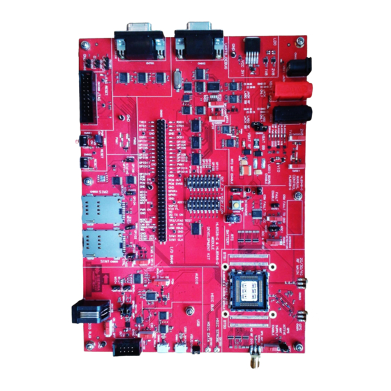
Page 12: Development Kit
Development Kit User Guide General Description 2.2. Development Kit Figure 1. AirPrime HL Series Development Kit (board version 1400897-I) 4114877 Rev 5.0 October 12, 2015... -
Page 13: Features
Development Kit User Guide General Description 2.2.1. Features Interfaces available on the development kit board include: Power supply connectors ON/OFF switch and pushbutton Reset pushbutton Tests points (TP) to access all signals of the embedded module ... -
Page 14: Figure 2. Available Connectors And Components On The Airprime Hl Series Development Kit
Development Kit User Guide General Description Figure 2. Available Connectors and Components on the AirPrime HL Series Development Kit 4114877 Rev 5.0 October 12, 2015... -
Page 15: Table 2. Connector And Switch Description
Development Kit User Guide General Description The following table describes the connectors and switches available on the development kit and the table after describe the different connections available. Table 2. Connector and Switch Description Connector / Description HL6528x HL75xx HL85xxx Switch ... -
Page 16: Table 3. Available Connections
Development Kit User Guide General Description Table 3. Available Connections Connector/Switch Connection Positive audio line Connect Pin 1 and Pin 2 with a jumper to bypass audio amplifier when using CN1103 a handset audio terminal Connect Pin 2 and Pin 3 with a jumper to enable audio amplifier when using a handset audio terminal Negative audio line ... - Page 17 Switch to “GPS ACTIVE ANT SUPPLY ENABLE” to enable GNSS active antenna supply (default setting) SW400 Discharge button for RTC battery. For internal Sierra Wireless use only. Switch to “1.8V” to manually detect the HL6528-1.8V module type (not used) SW500 ...
-
Page 18: Snap-In Connector
Development Kit User Guide General Description 2.2.3. Snap-In Connector The Snap-in connector houses the HL series embedded module and allows easy switching between any of the supported HL series embedded module. Note: The HL8549x module does not use this connector as it is soldered directly on the development kit. Figure 3. -
Page 19: Figure 5. Module Position For Hl6528X (With Label)
Development Kit User Guide General Description Figure 5. Module Position for HL6528x (with label) Figure 6. Module Position for HL75xx and HL85xxx After plugging an HL series embedded module in the Snap-in connector, attach the Snap-in cover as shown in the figure below. Figure 7. -
Page 20: Test Ports
Development Kit User Guide General Description 2.2.4. Test Ports There are a total of 64 test ports available in the AirPrime HL Series Development Kit. The following table lists the test port serigraphy and the corresponding signal names of the applicable HL series module. - Page 21 Development Kit User Guide General Description Test Test Port Board to Board HL6528x Signal HL75xx Signal HL85xxx Signal Port # Serigraphy Connector Pin # Name Name Name GPIO14 DEBUG_RX / GPIO14 CN201.68 SPI1_MRDY SPI1_MRDY GPIO14 GPIO15 GPIO15 CN201.64 SPI1_MOSI GPIO15 SPI1_MOSI NC2 / GPIO16...
-
Page 22: Special Solder For Jumper Solder Pads
Development Kit User Guide General Description Test Test Port Board to Board HL6528x Signal HL75xx Signal HL85xxx Signal Port # Serigraphy Connector Pin # Name Name Name SIM1 CLK CN201.49 UIM1_CLK UIM1_CLK UIM1_CLK Not available on the HL7518 and HL7548. Not available on the HL7528 and HL7549. -
Page 23: Interfaces
3. Interfaces 3.1. Power Supply Two power supply sources are available on the HL Series Development Kit: DC jack (via CN402) LABO connector (via CN401/CN400) Figure 9. Power Supply Connector (CN402, CN401 and CN400) Either power supplies can be used to supply the development kit, or they can be used to supply power to VBAT_BB and VBAT_RF separately depending on CN403 and CN404’s jumper configuration. -
Page 24: Control Functions
Development Kit User Guide Interfaces 3.2. Control Functions 3.2.1. Power ON/OFF Once the HL Series Development Kit is connected to an external source, the HL module will start monitoring the ON/OFF pin for a power on event. A power on event can be triggered by either: ... -
Page 25: Usb0
Development Kit User Guide Interfaces 3.3. USB0 The USB0 connection on the development kit is available from CN902. Note: This interface is not supported on the HL6528RD and HL6528RD-2.8V. The HL Series modules provide an I C interface for NMEA package delivery, and an I C to USB transceiver is embedded on the HL Series Development Kit. -
Page 26: Audio
Development Kit User Guide Interfaces 3.5. Audio Note: HL75xx and HL85xxx modules do not support analog audio. A headset jack (CN1105) is available on the development kit which allows the HL series module to connect to an audio interface. Switch SW1100 allows audio selection from direct analog audio connection or PCM codec conversion output, and switch SW1101 is used for activating an audio amplifier. -
Page 27: Sim1 And Sim2
CN804 CN600 CN803 CN800 U805 Figure 17. SIM1 and SIM2 Interface Note: Sierra Wireless recommends that SIM1 be used for single SIM applications. Table 6. SIM1 Connector Pin Description Pin Number Signal Name I/O Type Description 1V7 << 1V9 or... -
Page 28: Table 7. Sim2 Connector Pin Description
Development Kit User Guide Interfaces Table 7. SIM2 Connector Pin Description Pin Number Signal Name I/O Type Description UIM2_VCC 2V7 << 3V SIM Power Supply UIM2_RESET 2V7 << 3V SIM Reset UIM2_CLK 2V7 << 3V SIM Clock Not used Ground Not used UIM2_DATA 2V7 <<... -
Page 29: Uart1
Development Kit User Guide Interfaces For HL6528x with DSDS (SIM1 and SIM2) configuration, SW800 should be switched to position “SIM2 & GPIO” Short CN801 with a jumper to enable SIM1 insertion detection Short CN600 with a jumper to enable the SIM2 connector ... -
Page 30: Uart0/Spi1
Development Kit User Guide Interfaces Pin # Signal Name I/O Type Description Ground CT107 DSR RS232 (V24/V28) Data set ready CT105 RTS RS232 (V24/V28) Request to send CT106 CTS RS232 (V24/V28) Clear to send CT125 RI RS232 (V24/V28) Ring indicator 3.8. -
Page 31: Gpio Control
Development Kit User Guide Interfaces 3.9. GPIO Control Note: This interface is not supported on the HL6528RDx. Two switch sets, SW1000 and SW1001, are available on the Development Kit for GPIO test purposes. Figure 20. GPIOs Control Switches SW1000 enables GPIO1 to GPIO8; while SW1001 enables these GPIOs to be connected to VIO either as 1kΩ... -
Page 32: Jtag
Development Kit User Guide Interfaces 3.11. JTAG Figure 22. JTAG Connector Warning: This interface is not available for customer use. Default configurations should not be tampered with. 3.12. Antenna Connections Note: This interface is not supported on the HL6528RDx. Three SMA connectors are available on the HL Series Development Kit for main RF, 4G diversity and GNSS antenna connections. -
Page 33: Getting Started With The Hl Series Development Kit
4. Getting Started with the HL Series Development Kit This section describes how the AirPrime HL Series Development Kit is set up as well as describes communications testing, making calls and debugging with an embedded module. 4.1. Setting Up the Development Kit Perform the following steps before powering the Development Kit on. - Page 34 Getting Started with the HL Series Development Kit User Guide Development Kit 5. Connect a GSM or LTE antenna to CN303 of the Development Kit depending on the HL embedded module used. 6. Connect a GNSS antenna to CN304 of the Development Kit (when using an HL embedded module that supports GNSS).
-
Page 35: Figure 25. Airprime Hl Series Development Kit With An Hl6528 Embedded Module Inside The Snap-In Connector
Getting Started with the HL Series Development Kit User Guide Development Kit 9. To get NMEA output, connect a USB cable to USB0. 10. Connect a 4V power supply unit to CN402. Note: Make sure that Pin 2 and Pin 3 of CN403, as well as Pin 1 and Pin 2 of CN402 are connected with a jumper when using a 4V power supply unit. -
Page 36: Switching The Development Kit On
Getting Started with the HL Series Development Kit User Guide Development Kit 4.2. Switching the Development Kit On The Development Kit will automatically be powered on if Pin 1 and Pin 2 of CN601 are connected with a jumper. Otherwise, push SW601 for approximately 2 seconds to power the Development Kit on. CN601 SW601 Figure 26. -
Page 37: Make A Voice Call
Getting Started with the HL Series Development Kit User Guide Development Kit Test communications using a PC terminal emulator (for example, HyperTerminal) by entering AT. The module should answer with OK. Figure 28. AT Communication with the AirPrime HL6528x 4.3.2. Make a Voice Call To make a voice call with the Development Kit, follow these steps. -
Page 38: Rf Communications With The Hl75Xx And Hl85Xxx
Getting Started with the HL Series Development Kit User Guide Development Kit 2. From a PC terminal emulator (for example, HyperTerminal), input AT+CPIN?. If the SIM card is ready, the module will respond with +CPIN: READY, otherwise it will return ERROR. 3. -
Page 39: Figure 29. At Communication With The Airprime Hl75Xx And Hl85Xxx
Getting Started with the HL Series Development Kit User Guide Development Kit Figure 29. AT Communication with the AirPrime HL75xx and HL85xxx To make a voice call with the Development Kit, follow these steps. 1. Ensure that: a power cable is connected to CN402 ... -
Page 40: Gps Communications With The Hl6528-G
Getting Started with the HL Series Development Kit User Guide Development Kit 2. From a PC terminal emulator (for example, HyperTerminal), input AT+CPIN?. If the SIM card is ready, the module will respond with +CPIN: READY, otherwise it will return ERROR. 3. -
Page 41: Gps Communications With The Hl854X-G
Getting Started with the HL Series Development Kit User Guide Development Kit CN304 CN402 CN700 CN902 SW900 4.6. GPS Communications with the HL854x-G To get GNSS NMEA output, ensure that: a power cable is connected to CN402 a GNSS antenna is connected to CN304, and ... -
Page 42: Other Hardware Settings
5.1. Getting SpyTracer Debugging Data (for HL6528x only) Note: Contact your Sierra Wireless representative for more details about the SpyTracer tool. To get SpyTracer debug data, follow these steps: 1. Ensure that: a UART RS232 cable is connected to UART0 (CN602) SW603 is switched to position “SPI/UART0”... - Page 43 Development Kit User Guide Other Hardware Settings Set up DEF and STR file settings as follows. b. Set up UART port settings as follows. 4114877 Rev 5.0 October 12, 2015...
- Page 44 Development Kit User Guide Other Hardware Settings 4. Configure mobile settings by clicking Configuration > Link…. a. Set up mobile settings as follows. 4114877 Rev 5.0 October 12, 2015...
- Page 45 Development Kit User Guide Other Hardware Settings 5. Click “Start”, then power on the development kit board. The screen should start printing information as shown in the figure below. 4114877 Rev 5.0 October 12, 2015...
- Page 46 6. Reference Documents AirPrime HL6 and HL8 Series AT Commands Interface Guide Reference Number: 4114680 AirPrime HL6528x Product Technical Specification Reference Number: 4114016 AirPrime HL6528x (Automotive) Product Technical Specification Reference Number: 4116503 AirPrime HL6528RDx Product Technical Specification Reference Number: 4117701 AirPrime HL7518 Product Technical Specification Reference Number: 4115834 AirPrime HL7519, HL7548 and HL7588 Product Technical Specification...
- Page 47 7. Dev-Kit Schematic Diagrams 4114877 Rev 5.0 October 12, 2015...
- Page 48 Development Kit User Guide Dev-Kit Schematic Diagrams 4114877 Rev 5.0 October 12, 2015...
- Page 49 Development Kit User Guide Dev-Kit Schematic Diagrams 4114877 Rev 5.0 October 12, 2015...
- Page 50 Development Kit User Guide Dev-Kit Schematic Diagrams 4114877 Rev 5.0 October 12, 2015...
- Page 51 Development Kit User Guide Dev-Kit Schematic Diagrams 4114877 Rev 5.0 October 12, 2015...
- Page 52 Development Kit User Guide Dev-Kit Schematic Diagrams 4114877 Rev 5.0 October 12, 2015...
- Page 53 Development Kit User Guide Dev-Kit Schematic Diagrams 4114877 Rev 5.0 October 12, 2015...
- Page 54 Development Kit User Guide Dev-Kit Schematic Diagrams 4114877 Rev 5.0 October 12, 2015...
- Page 55 Development Kit User Guide Dev-Kit Schematic Diagrams 4114877 Rev 5.0 October 12, 2015...
- Page 56 Development Kit User Guide Dev-Kit Schematic Diagrams 4114877 Rev 5.0 October 12, 2015...
- Page 57 Development Kit User Guide Dev-Kit Schematic Diagrams 4114877 Rev 5.0 October 12, 2015...
Need help?
Do you have a question about the AirPrime HL Development Kit and is the answer not in the manual?
Questions and answers