Sierra Wireless AirPrime XS1110 User Manual
Hide thumbs
Also See for AirPrime XS1110:
- Product technical specification (48 pages) ,
- Command reference manual (54 pages)
Table of Contents
Advertisement
Quick Links
Advertisement
Table of Contents

Subscribe to Our Youtube Channel
Related Manuals for Sierra Wireless AirPrime XS1110


Summary of Contents for Sierra Wireless AirPrime XS1110
- Page 1 AirPrime XS1110 Development Kit User Guide 41113415 Rev 2.0...
- Page 2 Although significant delays or losses of data are rare when wireless devices such as the Sierra Wireless product are used in a normal manner with a well-constructed network, the Sierra Wireless product should not be used in...
- Page 3 Preface Patents This product may contain technology developed by or for Sierra Wireless Inc. This product is manufactured or sold by Sierra Wireless Inc. or its affiliates under one or more patents licensed from MMP Portfolio Licensing. Copyright © 2020 Sierra Wireless. All rights reserved.
-
Page 4: Table Of Contents
Contents Introduction ............5 Hardware Overview . -
Page 5: Introduction
1: Introduction The main purpose of the Development Kit is to simplify the evaluation process for GNSS modules and to help testers operate our products with convenience and ease. Figure 1-1: Development Kit This device can communicate with computer devices via USB cable, and it must be used in conjunction with the software, GNSS Tool, for users to record all module data such as satellites’... -
Page 6: Hardware Overview
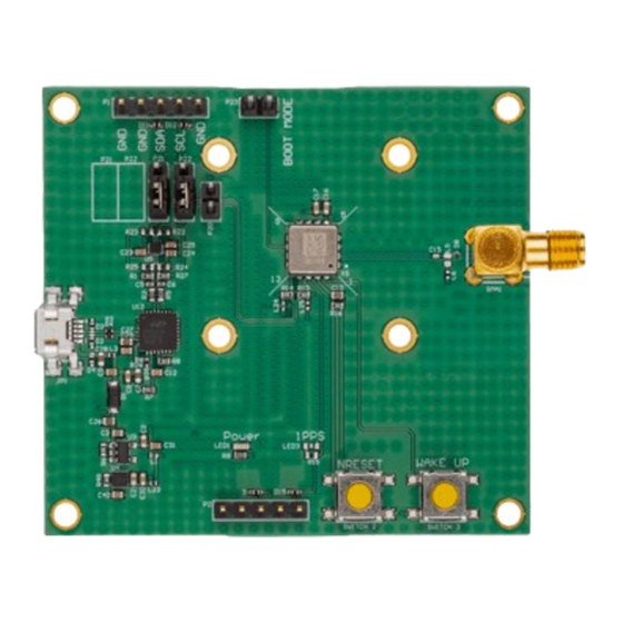
2: Hardware Overview The following figure identifies the location of the Development Kit’s connectors and other components. Figure 2-1: Development Kit Connectors and Components Refer to the subsequent chapter, Interfaces on page 7, for detailed description. Figure 2-2: RF SMA Connector Rev 2.0 Apr.20 41113415... -
Page 7: Interfaces
3: Interfaces This section describes the physical interfaces available on the Development Kit. Module The Development Kit includes an XS1110 module. Figure 3-1: XS1110 on the Development Kit Table 3-1: Module Details Component PCB Label Description Module XS1110 module Note that the XS1110 requires an external RF antenna to be connected to the RF SMA connector of the Development Kit. -
Page 8: Antenna Connection
Development Kit User Guide Antenna Connection The RF SMA connector is used to connect an external antenna for the XS1110 module. Figure 3-2: RF SMA Connector Table 3-2: Antenna Connector Details Component PCB Label Description RF SMA Connector SMA1 External antenna connector for the XS1110 module SYSTEM0 The SYSTEM0 header is used to set whether transmissions are done via UART... -
Page 9: I2C
Interfaces Figure 3-4: No Jumper on SYSTEM0 for UART Transmission To set transmission selection to I2C, short SYSTEM0 with a jumper. SYSTEM0 pins will then enter pull low status. The Development Kit must then be re-powered (by unplugging then replugging the power supply), after which the NRESET button must be pressed to reboot the module to change transmission selection from UART to I2C. -
Page 10: Boot Mode
Development Kit User Guide Table 3-4: I2C Header Details Component PCB Label Description 5-pin header signals; refer to Table 3-5 for details Table 3-5: I2C Header Pins Pin Number Pin Name Description Ground Ground RX0 / I2CSDA I2C serial data (in slave mode) TX0 / I2CSCL I2C serial clock (in slave mode) Ground... -
Page 11: 1Pps / Int
Interfaces 1PPS / INT Connectivity to peripheral devices is supported via the 1PPS and INT (for I2C) header. Figure 3-8: 1PPS / INT Header Table 3-7: 1PPS / INT Details Component PCB Label Description 5-pin header 1PPS / INT header Table 3-8: 1PPS / INT Header Pins Pin Number Pin Name... -
Page 12: Wake Up
Development Kit User Guide WAKE UP The WAKE UP pushbutton wakes the module up. Figure 3-9: WAKE UP Button Table 3-9: WAKE UP Button Details Component PCB Label Description Button SWITCH 3 Pushing the WAKE UP button wakes the module up from sleep mode. NRESET The NRESET pushbutton reboots the module. - Page 13 Interfaces the module’s UART access becomes accessible (default setting of • 115200kbps baud rate and update rate of 1Hz). Figure 3-11: Micro-B USB Connector and Power LED Table 3-11: Micro-B USB Connector Details Component PCB Label Description Micro-B USB connector Connects the Development Kit to a host device and provides access to the module’s UART interface...
-
Page 14: Software Usage
4: Software Usage System Requirements Operating System: Microsoft Windows 7, 8, and 10 • USB Driver: CP210x VCPInstaller.zip • · For Windows 7, Windows 8 or Windows 8.1, please use CP210xVCP driver v6.7 or the latest version (v6.7.5). · For Windows 10, please use CP210xVCP driver v6.7.5; v10.1.1 GUI Tool: GNSS Tool •... -
Page 15: Installing The Usb Driver
Software Usage Installing the USB Driver 1. Double click CP210x_VCP_Win.exe to begin driver installation: Figure 4-1: Driver Installation Folder 2. Click Install: Figure 4-2: Starting the Installation Process 3. After the installation is complete, you may need to restart your computer. Please follow the instructions on screen to restart your computer. - Page 16 Development Kit User Guide 5. Left click Device Manager and select Ports (COM &LPT). Check to see if a device named Silicon Labs CP210x USB to UART Bridge (COM#) is present. If so, the Development Kit is set up and ready for use. Figure 4-4: Accessing the Port Properties “COM9”...
-
Page 17: Using Gnss Tool
Software Usage Using GNSS Tool Microsoft Framework 4.5 or higher is required before you launch the GNSS Tool software on your PC. Double click GNSSTool.exe to start the application, the main screen of the program is shown below: Figure 4-5: Main Program Screen 1. - Page 18 Development Kit User Guide After the Development Kit is connected with the PC, please choose the correct <COM Port> and <Baud Rate>. Figure 4-6: COM Port Dialog If you want more information about the GNSS Tool software, refer to AirPrime GNSS Tool User Guide.
-
Page 19: Troubleshooting
5: Troubleshooting Setup Troubleshooting Table 5-1: Troubleshooting Causes and Solutions Problem Possible Cause Solution Cannot find USB was not set up properly Check to see if the Development Kit was GNSS device set up properly, and make sure that the device is receiving enough power through the USB cable (red LED should light up continuously). -
Page 20: Causes Of Poor Gnss Signals
Development Kit User Guide Causes of Poor GNSS Signals It is possible to have weak GNSS signal in the following situations: Table 5-2: Examples Where Poor GNSS Signals May Occur Inside a tunnel, where the GNSS signal is blocked. Underneath infrastructure (e.g. a bridge), where the GNSS signal is blocked. Inside a building, where the GNSS signal is blocked. - Page 21 Troubleshooting Table 5-2: Examples Where Poor GNSS Signals May Occur (Continued) Next to tall buildings, where the GNSS signal is weakened. Underneath forests or any other kinds of canopy where the GNSS signal is weakened. If the Development Kit is used inside a car which has anti-sunlight films on •...
-
Page 22: References
6: References Refer to the following documents for more information. Visit http://source.sierrawireless.com for the complete range of available documentation. 1. AirPrime XS1110 Product Technical Specification Reference number: 41113354 2. AirPrime GNSS Tool User Guide Reference number: 41111068 Rev 2.0 Apr.20...
Need help?
Do you have a question about the AirPrime XS1110 and is the answer not in the manual?
Questions and answers