Table of Contents
Advertisement
Quick Links
Advertisement
Table of Contents

Related Manuals for NewLine Elara Q+ Series


Summary of Contents for NewLine Elara Q+ Series
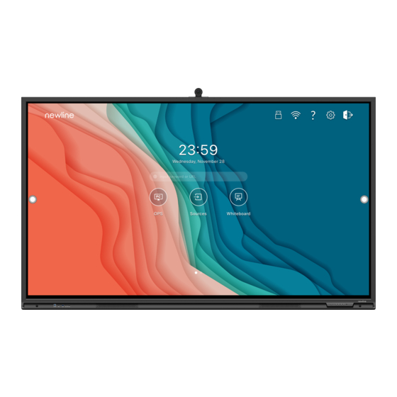
- Page 1 Elara(Q+ Series) Interactive Flat Panel Display Quick Start Manual...
- Page 2 Welcome to the world of NEWLINE Thank you for choosing the Q+ series Interactive Flat Panel Display. Please use NEWLINE this document to get the most out of your screen. This device complies with part 15 of the FCC Rules. Operation is subject to the following two conditions:(1) This device may not cause harmful interference, and (2) this device must accept any interference received, including interference that may cause undesired operation.
-
Page 3: Symbol Conventions
Symbol Conventions Symbols are used in this document to indicate operations that need particular attention. The symbols are defined as follows: Provides additional information to supplement operation in the main text. Indicates a potentially hazardous situation that, if not avoided, could result in equipment damage, data loss, performance deterioration, or unanticipated results. -
Page 4: Safety Instruction
Safety Instruction For your safety, please read the following instruction before you use the product. Serious injury or property damage may be caused by improper operations. Do not try to repair the product on your own. WARNING Disconnect the product from the power supply immediately if major failures occur. Major failures include the following: If smoke, a peculiar smell or an abnormal sound is discharged from the product. - Page 5 WARNING Do not put items on the top of the product. Do not put items, such as a container for liquid (a vase, flowerpot, cosmetics or liquid medicine) on the top of the product. If any water or liquid is spilled on the product, the product may short circuit cause fire or ...
- Page 6 CAUTION Do not install the product on carpet or cloth. Do not use a cloth such as table cloth to cover the product. Keep the product away from the radio. The product complies with the international EMI standard to prevent radio interference. However, interference may still exists and causes noise in the radio.
- Page 7 CAUTION may be damaged.
-
Page 8: Parts And Functions
Parts and Functions 1.1 Parts Front View ... - Page 9 Rear View Front Ports Camera Speakers Power Output Plug Power On/Off Power Supply Plug Front Buttons Power Switch Remote Control Receiver SDM-S Slot Light Sensor Rear Ports Proximity Sensor Wi-Fi Module Slot OPS Port Microphone Notes: SDM-S is Smart Display Module Small. ...
- Page 10 1.2 Ports CAUTION Front USB ports and rear USB 3.0/USB 2.0 ports switch connections based on signal sources. If the current signal source is reading the data from an external product connecting to the port, please switch the signal source after the data reading is complete. Otherwise, the data or product may be damaged.
-
Page 11: Front Buttons
WARNING The rear power output port is supplies 5 V/2 A (maximum) power. Please contact Newline to purchase the power AC adapter for powering external devices. Please do not connect any products which require power than listed. Doing so may cause injury or damage to the panel. -
Page 12: Remote Control
Buttons Operations Functions Long press for more Power off than 2 seconds Solid red color : Display is in shut down mode Short press Adjust the Volume Short press Adjust the Brightness Short press Go to the home page Short press Open the Quick Setting menu Long press for 5... - Page 13 Buttons Operations Power On/Off Go to the Home Page Directional Pad Confirm/OK Press once to freeze the current screen. Press again to exit freeze function Enter the Source Selection Page Return to Previous/Exit App switcher Open the Quick Setting menu on the embedded operating system.
- Page 14 Installation Guide 2.1 Safety Precautions Installation Environment...
-
Page 15: Installation Precautions
Installation Direction 2.2 Installation Precautions Weight Loading Weight of the panel: 143lb/ 65kg (86INCH), 110lb/50 kg (75INCH), 86lb/ 39kg (65INCH) When using a mobile stand, ensure that the weight of the product is less than the loading capacity of the mobile stand. When using the wall-mount bracket, ensure that the wall can support the weight of the ... - Page 16 For any problem, please contact our support desk. Our company is not responsible for any damage or losses incurred by users if the users fails to follow the instructions. Ventilation Ensure adequate ventilation and/or an air conditioned environment. We recommend keeping certain distances from the side of the product to the wall or panels.
-
Page 17: Installation
2.3 Installation The dimensions of the four bracket mounting holes on the back panel are VESA MIS-F compliant (86INCH or 75INCH: 800 x 400 mm/31.50 x 15.75 in; 65INCH: 600 x 400 mm/23.62 x 15.75 in). Use metric M8 screws with a length of 10 mm to 15 mm (0.40 to 0.59 in) to secure the touch screen to the mountingsystem. - Page 18 2.4 Installing the Wi-Fi Module Wi-Fi Module does not support hot plugging. Therefore, you must insert or remove the Wi-Fi Module when the display is powered off. Otherwise, the panel display or Wi-Fi Module may be damaged. The Wi-Fi Module is put in accessary box with an independent package, please install it onto panel referring to following steps.
- Page 19 2.5 Installing the Camera The camera is put in accessary box with an independent package, please install it onto panel referring to following steps. Use the two screws along with camera to fix. Remove the silicone cover from the middle port on the top of the panel display, then insert the camera.
- Page 20 2.6 Installing the OPS (Optional) The OPS does not support hot plugging. Therefore, you must insert or remove the OPS when the display is powered off. Otherwise, the display or OPS may be damaged. You will need to purchase the OPS separately. Perform the following steps to install the OPS. Step 1 Unscrew the M4 screws by hand to remove the OPS protective cover.
- Page 21 Step 2 Insert the SDM-S into the port on the rear of the panel until firmly seated, using the 2 screws to secure it. Please install SDM-S first before you hang panel on the wall.
-
Page 22: Power On/Off
Power On/Off 3.1 Power On Step 1 Ensure the power cable is fully seated into the panel and wall outlet before powering on the panel. Please confirm your wall outlet supports a power range of 100V to 240V with frequency at 50 Hz/60 Hz ± 5% and is fully grounded. The power outlet should be installed near the equipment and should be easily accessible. - Page 23 In the Save session page, select your session documentations and then tap , you can store your session documentations to the USB flash device. Then tap END, the Warning dialog box will be displayed as shown in the following figure. In the Warning dialog box, tap POWER OFF to turn off the display, and the power ...
- Page 24 Please properly shut down the panel before disconnecting the power source or it may cause damage. Accidental power failure may cause damage to the panel. Do not repeatedly turn the power on & off in a short period of time as it may cause malfunction. ...
- Page 25 Operating Profile Logon When the panel is powered on, the panel will show all the registered accounts. Tap the icon to enter the 6 digits passkey which is set when you first time operating the panel, tap the icon to back to the previous page, tap Change passkey to change your passkey, tap icon to make the system enter restart, sleep or power off state.
- Page 26 More Information Newline Assistant Please visit our website (https://newline-interactive.com) and choose Support > Downloads > Q+ series to download the Newline Assistant installation package. For More Information Please visit our website (https://newline-interactive.com) and choose Support > Downloads > Q+ series to download User Manual for detailed instruction manual.
Need help?
Do you have a question about the Elara Q+ Series and is the answer not in the manual?
Questions and answers