Table of Contents
Advertisement
Quick Links
RU50...-S18-...
DE
Kurzbetriebsanleitung
Ultraschallsensoren – RU50...-S18-...
Weitere Unterlagen
Anschließen
Ergänzend zu diesem Dokument finden Sie im Internet unter
Gerät gemäß „Wiring diagrams" anschließen.
➤
www.turck.com
folgende Unterlagen:
■
In Betrieb nehmen
Datenblatt
■
Konformitätserklärungen
Nach Anschluss der Leitungen und Aufschalten der Versor-
gungsspannung geht das Gerät automatisch in Betrieb.
Zu Ihrer Sicherheit
Betreiben
Bestimmungsgemäße Verwendung
Die Ultraschallsensoren erfassen berührungslos die An-
wesenheit von festen oder flüssigen Objekten sowie den
Falscher Einsatz des Sensors
Abstand zu den Objekten.
Mögliche Sachschäden durch Fehlfunktion
Die Geräte dürfen nur wie in dieser Anleitung beschrieben
➤
verwendet werden. Jede andere Verwendung gilt als nicht
bestimmungsgemäß. Für daraus resultierende Schäden
➤
übernimmt Turck keine Haftung.
Naheliegende Fehlanwendung
Geräte mit Schaltausgang – LED-Funktionen
Die Geräte sind keine Sicherheitsbauteile und dürfen nicht
LED
zum Personen- oder Sachschutz eingesetzt werden.
gelb
Allgemeine Sicherheitshinweise
aus
■
Nur fachlich geschultes Personal darf das Gerät montie-
ren, installieren, betreiben, parametrieren und instand
Geräte mit Analogausgang – LED-Funktionen
halten.
■
Nicht alle Objekte werden vom Sensor gleich gut erkannt.
LED
Die Erkennung des Objekts vor dem regulären Betrieb
gelb
prüfen.
aus
Produktbeschreibung
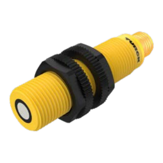
Geräteübersicht
Siehe Abb. 1
Funktionen und Betriebsarten
Typ
Ausgang
Anwendung
RU50U-S18-AP...
1 Schaltausgang
Reflexionstaster
(PNP)
RU50L-S18-AP...
1 Schaltausgang
Reflexionsschranke
(PNP)
RU50U-S18-AN...
1 Schaltausgang
Reflexionstaster
(NPN)
RU50L-S18-AN...
1 Schaltausgang
Reflexionsschranke
(NPN)
RU50U-S18-LI...
1 Analogausgang
Reflexionstaster
(4...20 mA)
RU50U-S18-LU...
1 Analogausgang
Reflexionstaster
(0...10 V)
Montieren
Die Sensoren dürfen in beliebiger Ausrichtung montiert
werden. Das maximale Anziehdrehmoment bei der Befesti-
gung des Sensors beträgt 2 Nm.
Montagefläche und Umgebung reinigen.
➤
Bei Verwendung einer Montagehilfe: Sensor in der Monta-
➤
gehilfe befestigen.
Den Sensor oder die Montagehilfe am vorgesehenen
➤
Einsatzort montieren.
Sicherstellen, dass der rückwärtige Stecker erreichbar
➤
bleibt.
Sensor so montieren, dass keine relevanten Objekte inner-
➤
halb der Blindzone liegen. Blindzone und Erfassungsbe-
reich entnehmen Sie Abb. 2. Bei Verwendung von mehr als
einem Ultraschallsensor in einer Applikation: Überschnei-
dung der Schallkeulen vermeiden. Eine Überschneidung
kann auftreten, wenn zwei Sensoren näher als 250 mm
zueinander montiert sind.
EN
Ultrasonic Sensors – RU50...-S18-...
Other documents
Besides this document, the following material can be found
on the Internet at www.turck.com:
■
Data sheet
■
Declarations of conformity
For your safety
Intended use
The ultrasonic sensors detect the presence of solid or liquid
ACHTUNG
objects and the distance to those objects without making
physical contact.
The devices must only be used as described in these instruc-
Materialablagerungen auf der Oberfläche des Schall-
tions. Any other use is not in accordance with the intended
wandlers vermeiden.
use. Turck accepts no liability for any resulting damage.
Blindzone des Sensors freihalten. Die Blindzone S
min
entnehmen Sie den technischen Daten.
Obvious misuse
The devices are not safety components and must not be
used for the protection of persons or property.
Bedeutung
Objekt im Teach-Bereich (RU50U-...), Reflektor
General safety instructions
erkannt (RU50L-...), Schaltausgang ein
■
The device must only be mounted, installed, operated,
kein Objekt im Teach-Bereich,
parameterized and maintained by trained and qualified
Schaltausgang aus
personnel.
■
Not all objects are detected equally well by the sensor. The
Bedeutung
detection of the object must be checked by the user prior
to normal operation.
Objekt innerhalb des Teach-Bereichs
kein Objekt im Teach-Bereich
Product description
Device overview
See fig. 1
Functions and operating modes
Type
RU50U-S18-AP...
RU50L-S18-AP...
RU50U-S18-AN...
RU50L-S18-AN...
RU50U-S18-LI...
RU50U-S18-LU...
Installing
The sensors can be mounted in any direction. The maximum
tightening torque for fastening the sensor is 2 Nm.
Clean the mounting surface and its surroundings.
➤
When using a mounting aid: Fasten the sensor in the
➤
mounting aid.
Install the sensor or the mounting aid at the intended
➤
location.
Ensure that the rear plug connector is accessible.
➤
Install the sensor so that no relevant objects are located
➤
within the blind zone. Refer to fig. 2 for the blind zone and
detection range. If using more than one ultrasonic sensor
in an application: Avoid the overlapping of sonic cones.
An overlap can occur if two sensors are mounted closer
than 250 mm apart.
Quick Start Guide
Connection
Connect the device as shown in "Wiring diagrams".
➤
Commissioning
The device is operational automatically once the cables are
connected and the power supply is switched on.
NOTICE
Incorrect use of the sensor
Possible material damage to property due to malfunction
Prevent the accumulation of material deposits on the
➤
surface of the sonic transducer.
Keep the blind zone of the sensor clear. Refer to the
➤
Technical Data for the blind zone S
Devices with a switching output – LED functions
LED
Meaning
Yellow Object detected in the teach-in range (RU50U-...),
reflector detected (RU50L-...), switching output on
Off
No object in the teach-in range,
switching output off
Devices with an analog output – LED functions
LED
Meaning
Yellow Object within the teach-in range
Off
No object in the teach-in range
Output
Application
1 switching output
Diffuse mode
(PNP)
sensor
1 switching output
Retroreflective
(PNP)
sensor
1 switching output
Diffuse mode
(NPN)
sensor
1 switching output
Retroreflective
(NPN)
sensor
1 analog output
Diffuse mode
(4...20 mA)
sensor
1 analog output
Diffuse mode
(0...10 V)
sensor
2
15
of the sensor.
min
10
20x20 mm
5
ø 27 mm
0
-5
-10
-15
cm
0
10
20
30
40
RU50...
ext. teach
WH
BN
BU
pnp
BK
RU50...-S18-AP8X
ext. teach
2 WH
1 BN
3 BU
pnp
4 BK
RU50...-S18-AP8X-H1141
BU
ext. teach
WH
BN
npn
BK
RU50...-S18-AN8X
3 BU
ext. teach
2 WH
1 BN
npn
4 BK
RU50...-S18-AN8X-H1141
ext. teach
BK
BN
BU
WH
I
analog
RU50U-S18-LI8X
RU50...-S18-...
Ultrasonic sensor
Quick Start Guide
Doc-No. 100032566 2201
Additional
information see
turck.com
50
60
2 WH
+
3 BU
1 BN
–
4 BK
–
2 WH
3 BU
1 BN
+
4 BK
+
–
© Hans Turck GmbH & Co. KG | 100032566 2022-01
Advertisement
Table of Contents

Related Manuals for turck RU50-S18 Series


Summary of Contents for turck RU50-S18 Series
- Page 1 250 mm apart. einem Ultraschallsensor in einer Applikation: Überschnei- ext. teach dung der Schallkeulen vermeiden. Eine Überschneidung kann auftreten, wenn zwei Sensoren näher als 250 mm zueinander montiert sind. – analog RU50U-S18-LI8X © Hans Turck GmbH & Co. KG | 100032566 2022-01...
- Page 2 Reflector position Hans Turck GmbH & Co. KG | Witzlebenstraße 7, 45472 Mülheim an der Ruhr, Germany | Tel. +49 208 4952-0 | Fax +49 208 4952-264 | more@turck.com | www.turck.com © Hans Turck GmbH & Co. KG | 100032566 2022-01...
- Page 3 Dégâts matériels possibles en raison d'un dysfonctionne- Las fallas pueden provocar posibles daños materiales a la ment aux indications figurant dans la présente notice. Toute al uso previsto. Turck no se responsabiliza de los daños ment propiedad autre utilisation est considérée comme non conforme. La derivados de dichos usos.
- Page 4 Reflector position Hans Turck GmbH & Co. KG | Witzlebenstraße 7, 45472 Mülheim an der Ruhr, Germany | Tel. +49 208 4952-0 | Fax +49 208 4952-264 | more@turck.com | www.turck.com © Hans Turck GmbH & Co. KG | 100032566 2022-01...
- Page 5 는 경우: 음파 원뿔이 겹치지 않게 하십시오. 두 센서가 250 1 BN mm보다 가까운 거리에 설치되면 겹칠 수 있습니다. 4 BK 4 BK 연결 “Wiring diagrams”에 따라 장치를 연결하십시오. RU50…-S18-AN8X-H1141 ➤ ext. teach – analog RU50U-S18-LI8X © Hans Turck GmbH & Co. KG | 100032566 2022-01...
- Page 6 Reflector position Hans Turck GmbH & Co. KG | Witzlebenstraße 7, 45472 Mülheim an der Ruhr, Germany | Tel. +49 208 4952-0 | Fax +49 208 4952-264 | more@turck.com | www.turck.com © Hans Turck GmbH & Co. KG | 100032566 2022-01...
Need help?
Do you have a question about the RU50-S18 Series and is the answer not in the manual?
Questions and answers