
Related Manuals for turck RU600U Series


Summary of Contents for turck RU600U Series
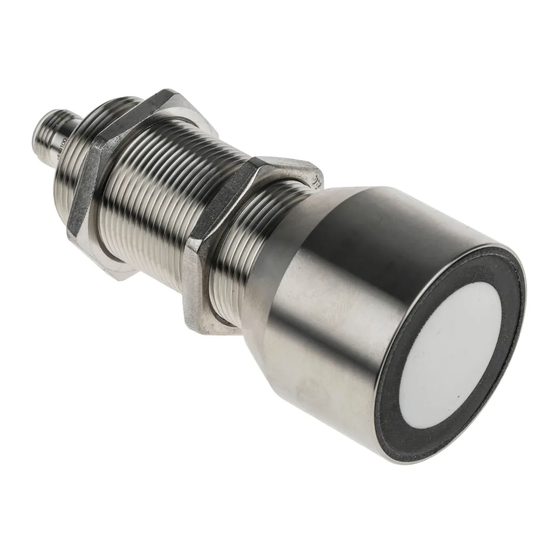
- Page 1 Your Global Automation Partner RU… High End Ultrasonic Sensors Instructions for Use...
- Page 2 Hans Turck GmbH & Co. KG | T +49 208 4952-0 | F +49 208 4952-264 | more@turck.com | www.turck.com...
-
Page 3: Table Of Contents
Feedback about these instructions................ 5 Notes on the Product ......................... 6 Product identification..................... 6 Scope of delivery ...................... 6 Legal requirements...................... 6 Turck service........................ 6 For Your Safety............................ 7 Intended use........................ 7 Obvious misuse........................ 7 General safety instructions.................... 7 Product Description ........................... 8 Device overview ...................... - Page 4 11 Maintenance............................ 54 12 Repair.............................. 54 12.1 Returning devices...................... 54 13 Disposal .............................. 54 14 Technical Data........................... 55 15 Turck Subsidiaries - Contact Information .................. 56 Hans Turck GmbH & Co. KG | T +49 208 4952-0 | F +49 208 4952-264 | more@turck.com | www.turck.com...
-
Page 5: About These Instructions
This symbol denotes actions that the user must carry out. RESULTS OF ACTION This symbol denotes relevant results of actions. Other documents Besides this document the following material can be found on the Internet at www.turck.com: Data sheet Commissioning manual IO-Link devices IO-Link parameters manual... -
Page 6: Notes On The Product
CAD files in numerous export formats. The contact details of Turck subsidiaries worldwide can be found on p. [} 56]. Hans Turck GmbH & Co. KG | T +49 208 4952-0 | F +49 208 4952-264 | more@turck.com | www.turck.com... -
Page 7: For Your Safety
The product is designed according to state-of-the-art technology. However, residual risks still exist. Observe the following warnings and safety notices to prevent damage to persons and property. Turck accepts no liability for damage caused by failure to observe these warning and safety notices. -
Page 8: Product Description
Only one LED can be active at one time. If an LED is active, all four indication points are lit. Hans Turck GmbH & Co. KG | T +49 208 4952-0 | F +49 208 4952-264 | more@turck.com | www.turck.com... -
Page 9: Properties And Features
Properties and features Smooth sonic transducer front Cylindrical design, potted M12 × 1 male connector Adjustable measuring range Temperature compensation NO/NC programmable Transmission of process value and parameterization via IO-Link Operating principle Ultrasonic sensors are designed for the non-contact and wear-free detection of a variety of tar- gets by means of sound waves. -
Page 10: Functions And Operating Modes
The output behaves as follows: blind detection range zone Fig. 5: Diffuse mode sensor with NC function – Behavior of the switching output Hans Turck GmbH & Co. KG | T +49 208 4952-0 | F +49 208 4952-264 | more@turck.com | www.turck.com... - Page 11 Diffuse mode sensor with NO function When used a diffuse mode sensor with an NO function, a switching point is taught in for a switch output. The output behaves as follows: blind detection range zone Fig. 6: Diffuse mode sensor with NO function – Behavior of the switching output Window function The start and end point of the switch window range can be set for the outputs.
- Page 12 Fig. 9: Analog output – output behavior Fig. 10: Analog output inverted – output behavior Hans Turck GmbH & Co. KG | T +49 208 4952-0 | F +49 208 4952-264 | more@turck.com | www.turck.com...
-
Page 13: Retroreflective Mode
4.4.3 Retroreflective mode When used as a retroreflective sensor, the sensor detects the echo of the ultrasonic waves of the taught reflector. The reflector can be any object with a surface that is as smooth as possible. The sensor generates a short switching window around the position of the reflector and de- tects the echo. - Page 14 Inactive sensors output the valid values that were last measured. The outputs can be used in the normal way. IO-Link operation is not possible in this mode. Hans Turck GmbH & Co. KG | T +49 208 4952-0 | F +49 208 4952-264 | more@turck.com | www.turck.com...
- Page 15 Opposed mode Two sensors with the same power and range are required for opposed mode. One sensor oper- ates in this mode as the emitter and the other sensor as the receiver. The devices are positioned and aligned opposite each other. This makes it possible to double the effective range of the sensors.
-
Page 16: Technical Accessories
2 m, sheathing material: ø 15 PVC, black; cULus approval; other M12 x 1 cable lengths and types available, see www.turck.com 11.5 Hans Turck GmbH & Co. KG | T +49 208 4952-0 | F +49 208 4952-264 | more@turck.com | www.turck.com... - Page 17 57,2 44,5 10,3 In addition to the above connection cables, Turck also offers other cable types for specific ap- plications with the correct terminals for the device. More information on this is available from the Turck product database at www.turck.de/products in the Connectivity area.
-
Page 18: Installing
Fig. 13: RU130… wave pattern 100x100 mm 100x100 mm ø 27 mm ø 27 mm -120 Fig. 14: RU300… wave pattern Fig. 15: RU600… wave pattern Hans Turck GmbH & Co. KG | T +49 208 4952-0 | F +49 208 4952-264 | more@turck.com | www.turck.com... -
Page 19: Connection
Connection „ Connect the female connector of the connection cable to the male connector of the sensor. „ Connect the open end of the connection cable to the power supply and/or processing units. Connection diagram 2 WH analog 3 BU 1 BN teach-in IO-Link... -
Page 20: Connection - Synchronization Mode
4: RU40U… RU130U… RU300U… RU600U… 22 ms 17.4 ms 37.4 ms 75.4 ms Hans Turck GmbH & Co. KG | T +49 208 4952-0 | F +49 208 4952-264 | more@turck.com | www.turck.com... -
Page 21: Connection - Release Mode
Connection diagram of the master sensor in synchronization mode Pin assignment Pin 1 +24 VDC 2 WH Pin 2 Output 2 (analog output or switching output) 3 BU 1 BN Pin 3 Pin 4 Synchronization output, connected to pin 5 of the 5 GY 4 BK slaves... - Page 22 Output signal for object detection, signal according 5 GY 4 BK to the table below Pin 5 Trigger input, connected to pin 4 of the emitter Hans Turck GmbH & Co. KG | T +49 208 4952-0 | F +49 208 4952-264 | more@turck.com | www.turck.com...
-
Page 23: Commissioning
Commissioning The device is operational automatically once the cables are connected and the power supply is switched on. V2.0 | 2021/06... -
Page 24: Operation
In IO-Link mode the LEDs have the following indication function: LED indication Meaning Green, IO-Link mode started lit with short interruptions Hans Turck GmbH & Co. KG | T +49 208 4952-0 | F +49 208 4952-264 | more@turck.com | www.turck.com... -
Page 25: Setting
Setting The ultrasonic sensor has two outputs with individually adjustable limits. Output 2 is factory set as an analog output and can be used either as a current output, a voltage output or as a switch- ing output. The user can set an individual switching point as well as a double switching point for the switching outputs. -
Page 26: Setting Via Teach Adapter
The individual switching point has been taught in successfully if the green LED flashes for 1.5 s at a frequency of 5 Hz. Hans Turck GmbH & Co. KG | T +49 208 4952-0 | F +49 208 4952-264 | more@turck.com | www.turck.com... - Page 27 Window function – setting the switching range Window function Out1 Out2 GND/T1 > 2 s 7 s GND/T1 > 8 s 13 s LED GN 1 × 1 Hz LED GN 2 × 1 Hz Cancel Measure and save /T2 > 2 s GND/T1 >...
- Page 28 The output function has been successfully inverted as an NC contact if the yellow LED flashes for 1.5 s at a frequency of 5 Hz. Hans Turck GmbH & Co. KG | T +49 208 4952-0 | F +49 208 4952-264 | more@turck.com | www.turck.com...
- Page 29 Inverting the output function (NO/NC) Invert logic Out1 Out2 GND/T1 > 2 s 7 s GND/T1 > 8 s 13 s LED GN 1 × 1 Hz LED GN 2 × 1 Hz Invert GND/T1 > 14 s LED YE 3 × 1 Hz LED YE LED GN 1.5 s ×...
- Page 30 The sensor is set successfully as a retroreflective sensor if the green LED flashes for 1.5 s at a frequency of 5 Hz. Hans Turck GmbH & Co. KG | T +49 208 4952-0 | F +49 208 4952-264 | more@turck.com | www.turck.com...
- Page 31 Reset to factory settings Factory reset Start factory reset GND/T1 > 14 s 19 s LED GN/YE 2 Hz Cancel Confirm /T2 > 2 s GND/T1 > 2 s LED YE 1 × 8 Hz LED GN 1 × 8 Hz Canceled Reset OK LED YE 1.5 s ×...
- Page 32 Output 2 is set successfully as a current output if the green LED flashes for 1.5 s at a frequency of 5 Hz. Hans Turck GmbH & Co. KG | T +49 208 4952-0 | F +49 208 4952-264 | more@turck.com | www.turck.com...
- Page 33 Setting output 2 as a current output NOTE If output 2 is set as a voltage output, the closer teach-in point corresponds to limit value 1 (0 V) and the teach-in point further away to limit value 2 (10 V). Out2: set Switch only: Current output...
- Page 34 Output 2 is set successfully as a switching output if the green LED flashes for 1.5 s at a frequency of 5 Hz. Hans Turck GmbH & Co. KG | T +49 208 4952-0 | F +49 208 4952-264 | more@turck.com | www.turck.com...
-
Page 35: Setting By Manual Bridging (Shorting)
Setting by manual bridging (shorting) Selecting the output „ Select switching output 1: Bridge pin 3 (BU) with pin 5 (GY) for 2…7 s. „ Select output 2: Bridge pin 3 (BU) with pin 5 (GY) for 8…13 s. Setting the switching point Switching point Out1 Out2... - Page 36 The switching points have been successfully taught in if the green LED flashes for 1.5 s at a frequency of 5 Hz. Hans Turck GmbH & Co. KG | T +49 208 4952-0 | F +49 208 4952-264 | more@turck.com | www.turck.com...
- Page 37 Window function – switching between hysteresis and window Choice: * Set window window / function before hysteresis* Out1 Out2 GND/T1 > 2 s 7 s GND/T1 > 8 s 13 s LED GN 1 × 1 Hz LED GN 2 × 1 Hz Measure and save GND/T1 >...
- Page 38 1.5 s at a frequency of 5 Hz. The output function has been successfully inverted as an NC contact if the yellow LED flashes for 1.5 s at a frequency of 5 Hz. Hans Turck GmbH & Co. KG | T +49 208 4952-0 | F +49 208 4952-264 | more@turck.com | www.turck.com...
- Page 39 Setting operation as a retroreflective sensor Retroreflective sensor Position sensor UB/T2 > 20 s LED YE 1 × 1 Hz Fail LED GN/YE LED GN 1.5 s × 5 Hz 1.5 s × 5 Hz Normal operation Fig. 34: Setting operation as a retroreflective sensor „...
- Page 40 The device has been successfully reset to the factory settings if the green LED flashes for 1.5 s at a frequency of 5 Hz. Hans Turck GmbH & Co. KG | T +49 208 4952-0 | F +49 208 4952-264 | more@turck.com | www.turck.com...
- Page 41 Setting output 2 as a current output NOTE If output 2 is set as a current output, the closer teach-in point corresponds to limit value 1 (4 mA) and the teach-in point further away to limit value 2 (20 mA). Out2: set Switch only: Current output...
- Page 42 Output 2 is set successfully as a voltage output if the green LED flashes for 1.5 s at a frequency of 5 Hz. Hans Turck GmbH & Co. KG | T +49 208 4952-0 | F +49 208 4952-264 | more@turck.com | www.turck.com...
- Page 43 Setting output 2 as a switching output Out2: set Switch only: Current output Voltage output inverted Out1 /T2 > /T2 > /T2 > 2 s 7 s 8 s 16 s 14 s 19 s LED YE 1 × 1 Hz LED YE 2 ×...
-
Page 44: Setting Via The Pushbuttons
The individual switching point has been taught successfully if the green LED flashes for 1.5 s at a frequency of 5 Hz. Hans Turck GmbH & Co. KG | T +49 208 4952-0 | F +49 208 4952-264 | more@turck.com | www.turck.com... - Page 45 Window function – setting the switching range Window function Out1 Out2 GND/T1 > 2 s 7 s GND/T1 > 8 s 13 s LED GN 1 × 1 Hz LED GN 2 × 1 Hz Cancel Measure and save /T2 > 2 s GND/T1 >...
- Page 46 The hysteresis function has been taught in successfully if the yellow LED flashes for 1.5 s at a frequency of 5 Hz. Hans Turck GmbH & Co. KG | T +49 208 4952-0 | F +49 208 4952-264 | more@turck.com | www.turck.com...
- Page 47 Inverting the output function (NO/NC) Invert logic Out1 Out2 GND/T1 > 2 s 7 s GND/T1 > 8 s 13 s LED GN 1 × 1 Hz LED GN 2 × 1 Hz Invert GND/T1 > 14 s LED YE 3 × 1 Hz LED YE LED GN 1.5 s ×...
- Page 48 The sensor is set successfully as a retroreflective sensor if the green LED flashes for 1.5 s at a frequency of 5 Hz. Hans Turck GmbH & Co. KG | T +49 208 4952-0 | F +49 208 4952-264 | more@turck.com | www.turck.com...
- Page 49 Reset to factory settings Factory reset Start factory reset GND/T1 > 14 s 19 s LED GN/YE 2 Hz Cancel Confirm /T2 > 2 s GND/T1 > 2 s LED YE 1 × 8 Hz LED GN 1 × 8 Hz Canceled Reset OK LED YE 1.5 s ×...
- Page 50 Output 2 is set successfully as a current output if the green LED flashes for 1.5 s at a frequency of 5 Hz. Hans Turck GmbH & Co. KG | T +49 208 4952-0 | F +49 208 4952-264 | more@turck.com | www.turck.com...
- Page 51 Setting output 2 as a voltage output NOTE If output 2 is set as a voltage output, the closer teach-in point corresponds to limit value 1 (0 V) and the teach-in point further away to limit value 2 (10 V). Out2: set Switch only: Current output...
-
Page 52: Setting Via Io-Link
RU Series ultrasonic sensors Further information on operating modes and parameters in IO-Link mode is provided in the IO-Link Parameters manual. Hans Turck GmbH & Co. KG | T +49 208 4952-0 | F +49 208 4952-264 | more@turck.com | www.turck.com... -
Page 53: Troubleshooting
Troubleshooting If the device does not function as expected, first check whether ambient interference is present. If there is no ambient interference present, check the connections of the device for faults. If there are no faults, there is a device malfunction. In this case, decommission the device and replace it with a new device of the same type. -
Page 54: Maintenance
Disposal The devices must be disposed of correctly and must not be included in general household garbage. Hans Turck GmbH & Co. KG | T +49 208 4952-0 | F +49 208 4952-264 | more@turck.com | www.turck.com... -
Page 55: Technical Data
Technical Data Technical data RU40U…-M18… RU130U…-M18… RU130U…-M30… Blind zone S 2.5 cm 15 cm 15 cm Operating range 40 cm 130 cm 130 cm Resolution 0.5 mm 1 mm 1 mm Minimum size – switching range 5 mm 10 mm 10 mm –... -
Page 56: Turck Subsidiaries - Contact Information
Turck Banner Malaysia Sdn Bhd Unit A-23A-08, Tower A, Pinnacle Petaling Jaya, Jalan Utara C, 46200 Petaling Jaya Selangor www.turckbanner.my Hans Turck GmbH & Co. KG | T +49 208 4952-0 | F +49 208 4952-264 | more@turck.com | www.turck.com... - Page 57 Mexico Turck Comercial, S. de RL de CV Blvd. Campestre No. 100, Parque Industrial SERVER, C.P. 25350 Arteaga, Coahuila www.turck.com.mx Netherlands Turck B. V. Postbus 297, NL-8000 AG Zwolle www.turck.nl Austria Turck GmbH Graumanngasse 7/A5-1, A-1150 Wien www.turck.at Poland TURCK sp.z.o.o.
- Page 58 Over 30 subsidiaries and over 60 representations worldwide! D102284 | 2021/06 D102284 www.turck.com...
Need help?
Do you have a question about the RU600U Series and is the answer not in the manual?
Questions and answers