Omron SYSMAC CP Series User Manual
Cpu unit hardware
Hide thumbs
Also See for SYSMAC CP Series:
- User manual (578 pages) ,
- Instruction & reference manual (467 pages) ,
- Programming manual (1175 pages)

Subscribe to Our Youtube Channel
Related Manuals for Omron SYSMAC CP Series


Summary of Contents for Omron SYSMAC CP Series
- Page 1 Cat. No. W613-E1-01 SYSMAC CP Series CP2E-E CP2E-S CP2E-N CP2E CPU Unit Hardware USER’S MANUAL...
- Page 2 No patent liability is assumed with respect to the use of the information contained herein. Moreover, because OMRON is constantly striving to improve its high-quality products, the information contained in this manual is subject to change without notice. Every precaution has been taken in the preparation of this manual. Neverthe- less, OMRON assumes no responsibility for errors or omissions.
- Page 4 SYSMAC CP Series CP2E-E CP2E-S CP2E-N CP2E CPU Unit Hardware User’s Manual Produced September 2019...
-
Page 5: Introduction
Introduction Thank you for purchasing a SYSMAC CP-series CP2E Programmable Controller. This manual contains information required to use the CP2E. Read this manual completely and be sure you understand the contents before attempting to use the CP2E. Intended Audience This manual is intended for the following personnel, who must also have knowledge of electrical sys- tems (an electrical engineer or the equivalent). -
Page 6: Cp2E Cpu Unit Manuals
CP2E CPU Unit Manuals Information on the CP2E CPU Units is provided in the following manuals. Refer to the appropriate manual for the information that is required. This Manual CP2E CPU Unit Hardware CP2E CPU Unit Software CP1E/CP2E CPU Unit Instructions User’s Manual(Cat. - Page 7 Manual Configuration The CP2E CPU manuals are organized in the sections listed in the following tables. Refer to the appro- priate section in the manuals as required. CP2E CPU Unit Hardware User’s Manual (Cat. No. W613) (This Manual) Section Contents Section 1 Overview and Specifica- This section gives an overview of the CP2E, describes its features, and tions...
- Page 8 Section Contents Section 10 Interrupts This section describes the interrupts that can be used with CP2E PLCs, including input interrupts and scheduled interrupts. Section 11 High-speed Counters This section describes the high-speed counter inputs, high-speed counter interrupts, and the frequency measurement function. Section 12 Pulse Outputs This section describes positioning functions such as trapezoidal control, jogging, and origin searches.
-
Page 9: Manual Structure
Manual Structure Page Structure and Icons The following page structure and icons are used in this manual. Level 1 heading 5 Installation and wiring Level 2 heading Installation Level 3 heading Level 2 heading Gives the current headings. Level 3 heading 5-2-1 Installation Location DIN Track Installation... - Page 10 Terminology and Notation Term Description E-type CPU Unit An essential model of CPU Unit that supports connections to Programmable Terminals and basic control applications using instructions such as basic, movement, arithmetic, and comparison instructions. Essential models of CPU Units are called “E -type CPU Units”...
- Page 11 Sections in this Manual Overview and Specifications Basic System Configuration and Devices Part Names and Functions Programming Device Installation and Wiring Troubleshooting Maintenance and Inspection Using Expansion Units and Expansion I/O Units Appendices CP2E CPU Unit Hardware User’s Manual(W613)
-
Page 12: Table Of Contents
CONTENTS Introduction ....................... 1 CP2E CPU Unit Manuals ................... 2 Manual Structure ....................... 5 Terms and Conditions Agreement................. 11 Safety Precautions ....................13 Precautions for Safe Use..................17 Operating Environment Precautions ..............21 Regulations and Standards..................22 Software Licenses and Copyrights ............... 23 Related Manuals ...................... - Page 13 Section 3 Part Names and Functions CPU Units ..........................3-2 3-1-1 E14/20 or N14/20 CPU Units ....................3-2 3-1-2 E30/40/60, S30/40/60 or N30/40/60 CPU Units................3-6 3-1-3 Common I/O Specifications....................... 3-12 3-1-4 Serial Communication Port ....................... 3-17 3-1-5 Analog Option Board for N -type CPU Units................
- Page 14 Section 7 Maintenance and Inspection Periodic Maintenance and Inspection ................... 7-2 7-1-1 Tools Required for Inspections....................7-2 7-1-2 Periodic Inspection........................7-2 7-1-3 Inspection and Maintenance ....................... 7-3 7-1-4 Unit Replacement Precautions....................7-4 Replacing the Battery in N/S -type CPU Units ..............7-5 Section 8 Using Expansion Units and Expansion I/O Units Analog Input Units........................
-
Page 15: Terms And Conditions Agreement
Omron’s exclusive warranty is that the Products will be free from defects in materials and workman- ship for a period of twelve months from the date of sale by Omron (or such other period expressed in writing by Omron). Omron disclaims all other warranties, express or implied. - Page 16 Disclaimers Performance Data Data presented in Omron Company websites, catalogs and other materials is provided as a guide for the user in determining suitability and does not constitute a warranty. It may represent the result of Omron’s test conditions, and the user must correlate it to actual application requirements. Actual perfor- mance is subject to the Omron’s Warranty and Limitations of Liability.
-
Page 17: Safety Precautions
Safety Precautions Definition of Precautionary Information The following notation is used in this manual to provide precautions required to ensure safe usage of a CP-series PLC. The safety precautions that are provided are extremely important to safety. Always read and heed the information provided in all safety precautions. Indicates an imminently hazardous situation which, WARNING if not avoided, will result in death or serious injury. - Page 18 WARNING Do not attempt to take any Unit apart while the power is being supplied. Doing so may result in electric shock. Do not touch any of the terminals or terminal blocks while the power is being supplied. Doing so may result in electric shock. Provide safety measures in external circuits (i.e., not in the Programmable Con- troller), including the following items, to ensure safety in the system if an abnormality occurs due to malfunction of the PLC or another external factor...
- Page 19 Caution Caution Be sure to sufficiently confirm the safety at the destination when you transfer the program or I/O memory or perform procedures to change the I/O memory. Devices connected to PLC outputs may incorrectly operate regardless of the operat- ing mode of the CPU Unit.
- Page 20 Caution Sufficiently check safety if I/O bit status or present values are monitored in the Ladder Section Pane or present values are monitored in the Watch Pane. If bits are set, reset, force-set, or force-reset by inadvertently pressing a shortcut key, devices connected to PLC outputs may operate incorrectly regardless of the operat- ing mode.
- Page 21 Precautions for Safe Use Observe the following precautions when using a CP-series PLC. Power Supply • Always use the power supply voltages specified in the user’s manuals. An incorrect voltage may result in malfunction or burning. • Take appropriate measures to ensure that the specified power with the rated voltage and fre- quency is supplied.
- Page 22 • Be sure that all the PLC terminal screws and cable connector screws are tightened to the torque specified in the relevant manuals. The tightening torque for the terminals on the CP1W- CIF11/CIF12-V1 terminal block is 0.23 N·m Incorrect tightening torque may result in malfunction. •...
- Page 23 • Do not drop the Unit or subject the Unit to unusual vibration and shock. Do so may result in failure or fire. • Confirm that no adverse effect will occur in the system before attempting any of the following. Not doing so may result in an unexpected operation.
- Page 24 • If the I/O Hold Bit is turned ON, the outputs from the PLC will not be turned OFF and will maintain their previous status when the PLC is switched from RUN or MONITOR mode to PROGRAM mode. Make sure that the external loads will not produce dangerous conditions when this occurs. (When operation stops for a fatal error, including those produced with the FALS instruction, all out- puts from PLC will be turned OFF and only the internal output status in the CPU Unit will be main- tained.)
-
Page 25: Operating Environment Precautions
Operating Environment Precautions Perform installation following the instructions in this manual Follow the instructions in this manual to correctly perform installation. Do not operate the control system in the following locations • Locations subject to direct sunlight • Locations subject to temperatures or humidity outside the range specified in the specifications •... -
Page 26: Regulations And Standards
Concepts EMC Directives OMRON devices are electrical components that are designed to be built into equipment and manu- facturing systems. OMRON devices that comply with EMC Directives also conform to the related EMC standards*, so that they can be more easily built into other devices or the overall machine. -
Page 27: Software Licenses And Copyrights
Software Licenses and Copyrights This product incorporates certain third party software. The license and copyright information associated with this software is shown at the following. Copyright (c) 2001-2004 Swedish Institute of Computer Science. All rights reserved. Redistribution and use in source and binary forms, with or without modification, are permitted provided that the following conditions are met: 1. -
Page 28: Related Manuals
The following manuals are related to the CP2E. Use them together with this manual. Manual name Cat. No. Model numbers Application Contents SYSMAC CP Series W613 CP2E-E To learn the hard- Describes the following information for CP2E CP2E CPU Unit Hard- ware specifications PLCs. -
Page 29: Overview And Specifications
Overview and Specifications This section gives an overview of the CP2E, describes its features, and provides its specifications. 1-1 CP2E Overview ..........1-2 1-1-1 Overview of Features . -
Page 30: Cp2E Overview
CP2E Overview 1-1-1 Overview of Features The SYSMAC CP2E Programmable Controller is a package-type PLC made by OMRON that is designed for easy application. The CP2E includes E -type CPU Units (essential models) that support connec- tions to Programmable Terminals and basic control applications using basic, movement, arithmetic, and... -
Page 31: Features
1 Overview and Specifications 1-1-2 Features System Configuration Network Model CP2E CPU Unit (An N -type CPU Unit with 40 I/O Points is shown here.) CX-Programmer CX-One Power supply and input terminals CP2W-BAT02 Battery (sold separately) Ethernet port Expansion Units (Can be mounted to N30/40/60 CPU Units) Commercially available 00 01 02 03... - Page 32 1 Overview and Specifications Programming, Setting, and Monitoring with the CX-Programmer The CX-Programmer is used as the Programming Device for the CP2E. Easy Connection with Computers Using Commercially Available USB/Ethernet Cables The CX-Programmer is connected using a commercially available USB/Ethernet cable between the computer’s USB/Ethernet port and the built-in USB/Ethernet port of the CP2E.
- Page 33 1 Overview and Specifications Quick-response Inputs By setting a built-in input to quick-response input operation, inputs with signal widths as small as 50 µs can be read with certainty regardless of the cycle time. Up to eight quick-response inputs can be used. Quick-response signal to photomicrosensor or other device Built-in input...
- Page 34 1 Overview and Specifications Complete High-speed Counter Functionality A high-speed counter input can be used by connecting a rotary encoder to a built-in input. A CP2E CPU Unit is equipped with more than one high-speed counter input, making it possible to control devices for multiple axes with a single PLC.
- Page 35 1 Overview and Specifications Versatile Pulse Control for Transistor Output CPU Units Fixed duty ratio pulse outputs can be output from the CPU Unit’s built-in outputs and used to perform positioning or speed control with a servomotor or a stepping motor that accepts pulse inputs. Up to four pulse outputs at 100 kHz are provided as standard features.
- Page 36 1 Overview and Specifications Built-in RS-232C Port for E/S -type CPU Units The E/S -type CPU Units have one built-in RS-232C port as a standard feature. Built-in RS-485 Port for S -type CPU Units The S -type CPU Units have one built-in RS-485 port as a standard feature. Mounting Serial Option Boards to N -type CPU Units UP to two Serial Communications Option Boards can be added to an N...
- Page 37 With the built-in Ethernet port, it is possible to connect the CX-Programmer to PLCs and exchange data between OMRON PLCs using Ethernet. It can also create an original communication procedure using TCP/IP or UDP/IP for the host application or communicate with PLCs from another manufacturer.
-
Page 38: Basic Operating Procedure
1 Overview and Specifications Basic Operating Procedure In general, use the following procedure. 1. Setting Devices and Hardware Connect the CPU Unit, Expansion I/O Units, and Expansion Units. Set the DIP switches on the Option Board and Expansion Units as required. Refer to Section 3 Part Names and Functions and Section 5 Installation and Wiring in the CP2E CPU Unit Hardware User’s Manual (Cat. -
Page 39: Specifications
1 Overview and Specifications Specifications 1-3-1 General Specifications The following table lists the general specifications of CP2E CPU Units. Item AC power supply DC power supply Model CP2E- D -A CP2E- D -D Enclosure Mounted in a panel Dimensions (H × D × W) CPU Unit with 14 or 20 I/O points (CP2E- 14/20D - ): 90mm ×80mm ×... -
Page 40: Characteristics
1 Overview and Specifications 1-3-2 Characteristics The following table gives the characteristics of CP2E CPU Units. Item CP2E-E CP2E-S CP2E-N Program capacity 4K steps 8K steps 10K steps FB capacity 4K steps 8K steps 10K steps Control method Stored program method I/O control method Cyclic scan with immediate refreshing Program language... - Page 41 1 Overview and Specifications Item CP2E-E CP2E-S CP2E-N Built-in output PWM outputs Frequency PWM output function not 2.0 to 6,553.5 Hz (in increments of 0.1 Hz) with 1 output or 2 Hz function (Models with included to 32,000 Hz (in increments of 1 Hz) with 1 output transistor out- Duty factor 0.0% to 100.0% (in increments of 0.1%)
- Page 42 1 Overview and Specifications Item CP2E-E CP2E-S CP2E-N Communica- Ethernet Physical layer None 100/10BASE-TX (Auto-MDIX) tions Media access CSMA/CD methiod Modulation Baseband Baud rate 100BASE-TX: 100Mbit/s 10BASE-T: 10Mbit/s • Half/full auto-negotiation for each port • Link speed auto-sensing for each port Transmission 100BASE-TX media...
-
Page 43: Functional Specifications
1 Overview and Specifications 1-3-3 Functional Specifications The following table gives the functional specifications of CP2E CPU Units. Function Description Cycle time Minimum cycle time Makes the cycle time consistent. manage- Cycle time monitoring Monitors the cycle time. ment CPU Unit Inputs High- High-speed pulse... - Page 44 1 Overview and Specifications Function Description Power sup- Memory protection Holding Area data, DM Area data, Counter Completion Flags, Counter Present ply man- Values and Auxiliary Area data are held even when power is turned OFF. agement Data is retained without battery even if the power supply is interrupted. Number of power interruptions counter The number of times power has been interrupted is counted.
-
Page 45: Basic System Configuration And Devices
Ü Basic System Configuration and Devices This section describes the basic system configuration and device models of the CP2E. 2-1 Basic System Configuration ........2-2 2-1-1 Basic System Configuration Using an E (S)-type CPU Unit . -
Page 46: Basic System Configuration
2 Basic System Configuration and Devices Basic System Configuration This section describes the system configurations using CP2E CPU Units. 2-1-1 Basic System Configuration Using an E/S -type CPU Unit The system configuration when using a CP2E E/S -type CPU Unit is shown below. Battery CP2W-BAT02 -type only) -
Page 47: Basic System Configuration Using An N
2 Basic System Configuration and Devices 2-1-2 Basic System Configuration Using an N -type CPU Unit The system configuration when using a CP2E N -type CPU Unit is shown below. Battery CP2W-BAT02 CP2E CPU Unit Expansion I/O Units Expansion Units DIN Track CP2E-N30D - Analog I/O... -
Page 48: Cpu Units
2 Basic System Configuration and Devices CPU Units This section describes the models of CP2E CPU Units. 2-2-1 CPU Unit Models The CP2E CPU Unit model numbers are configured as shown below. Power supply A: AC power supply CP2E- D: DC power supply Output type R: Relay outputs T: Transistor outputs, sinking... - Page 49 2 Basic System Configuration and Devices The following is a list of available CP2E CPU Unit models. -type CPU Units Number of built-in I/O Current Power points consumption supply Program DM Area Name and appearance Model number Output type Weight Number Number specifica-...
- Page 50 2 Basic System Configuration and Devices -type CPU Units Number of built-in I/O Current Power points consumption supply Program DM Area Name and appearance Model number Output type Weight Number Number specifica- capacity capacity Total 5 VDC 24 VDC tions inputs outputs CPU Unit with 30 I/O Points...
- Page 51 2 Basic System Configuration and Devices -type CPU Units Number of built-in I/O Current Power points consumption supply Program DM Area Name and appearance Model number Output type Weight Number Number specifica- capacity capacity Total 5 VDC 24 VDC tions inputs outputs CPU Unit with 14 I/O Points CP2E-N14DR-A 14...
-
Page 52: Optional Products
2 Basic System Configuration and Devices 2-2-2 Optional Products Optional Products for CPU Units Current consumption Name and appearance Model number Applications Weight 5 VDC 24 VDC − RS-232C Option Board CP1W-CIF01 Mounted in the option slot of an N -type 0.04A CPU Unit and can be used as an RS-232C... - Page 53 2 Basic System Configuration and Devices Current consumption Name and appearance Model number Applications Weight 5 VDC 24 VDC − − − Battery CP2W-BAT02 Mounted in an N/S -type CPU Unit. Mount the Battery when using the clock function. A Battery cannot be mounted to an E -type CPU Unit.
-
Page 54: Unit Versions Of Cpu Units
CP2E CPU Unit Product nameplate CP2E-N40DR-A CPU UNIT Lot No. 01819M Ver.1.0 OMRON Corporation MADE IN CHINA Lot No. Unit version (example for unit version 1.0) Confirming Unit Versions with Support Software CX-Programmer can be used to confirm the unit version of the CP2E CPU Units. -
Page 55: Expansion I/O Unit Or Expansion Unit
2 Basic System Configuration and Devices Expansion I/O Unit or Expansion Unit This section describes the connection of Expansion I/O Units or Expansion Units to a CP2E CPU Unit. 2-3-1 Expandable CPU Units • Expansion I/O Units and Expansion Units cannot be connected to E14/20 or N14/20 CPU Units. •... -
Page 56: Expansion I/O Units And Expansion Units
2 Basic System Configuration and Devices 2-3-4 Expansion I/O Units and Expansion Units Expansion I/O Units Current Specifications consumption Name and appearance Model number Weight Outputs Inputs − 8-point Input Unit CP1W-8ED Not provided. 8 inputs, 24 VDC 0.018A 200g 8-point Output Unit CP1W-8ER 8 relay outputs... - Page 57 2 Basic System Configuration and Devices Expansion Units Current consumption Name and appearance Model number Specifications Weight Analog I/O Unit CP1W-MAD11 2 analog inputs 0.083A 0.110A 250g 0 to 5 V, 1 to 5 V, 0 to 10 V, -10 to 10 V, 0 to 20 mA, and 4 to 20 mA 1 analog output 1 to 5 V, 0 to 10 V, -10 to 10 V, 0 to 20 mA, 4...
-
Page 58: Restrictions On System Configuration
2 Basic System Configuration and Devices Current consumption Name and appearance Model number Specifications Weight Temperature Sensor Unit CP1W-TS004 Thermocouple inputs K or J, 12 inputs 0.080A 0.050A 380g 2-3-5 Restrictions on System Configuration The following restrictions apply to the CP-series Expansion Units and CP-series Expansion I/O Units that can be connected to CP2E CPU Units. - Page 59 2 Basic System Configuration and Devices Restrictions by ambient temperature According to the ambient temperature, there are restrictions on power supply voltage and output load current for the DC-power-supply CPU Units. Refer to Output Specifications for Relay Outputs in 3-2-4 I/O Specifications for details. Restrictions on the Number of Simultaneously ON Points Use CP1W-32ER/ET/ET1 32-point Output Units with the number of simultaneously ON less than 24 points (75%).
-
Page 60: Unit Current Consumption And External Power Supply Capacity
2 Basic System Configuration and Devices Unit Current Consumption and External Power Supply Capacity This section describes the current consumption and external power supply capacity of units used by the CP2E. 2-4-1 External Power Supply Capacity When Expansion I/O Units or Expansion Units are Connected When connecting Expansion Units and Expansion I/O Units to an E30/40/60, S30/40/60 or N30/40/60 CPU Unit, or when using the external power supply, ensure the power supply capacity is satisfied as the... -
Page 61: Current Consumption
2 Basic System Configuration and Devices Calculation Example of the DC-Power-Supply CPU Units CPU Unit Expansion (I/O) Units Other Total Limit devices using PLC unit unit unit internal power supply CP2E- CP1W- CP1W- CP1W- CP1W-CIF01 N60DT-D 40EDT TS003 DA041 ≤1.2A 0.71A 0.16A 0.07A... - Page 62 2 Basic System Configuration and Devices -type CPU Units Current consumption I/O capacity Model number 5 VDC 24 VDC 14 I/O points CP2E-N14DR-A 0.15A 0.05A CP2E-N14DT-A 0.21A 0.02A CP2E-N14DR-D 0.15A 0.05A CP2E-N14DT-D 0.21A 0.02A CP2E-N14DT1-D 0.22A 0.02A 20 I/O points CP2E-N20DR-A 0.17A 0.06A...
- Page 63 2 Basic System Configuration and Devices Expansion I/O Units, Expansion Units and Option Board Units Current consumption Unit name Model number 5 VDC 24 VDC − Expansion I/O Units 8 inputs CP1W-8ED 0.018A 8 outputs CP1W-8ER 0.026A 0.044A − CP1W-8ET 0.075A CP1W-8ET1 16 outputs...
- Page 64 2 Basic System Configuration and Devices CP2E CPU Unit Hardware User’s Manual(W613) 2-20...
- Page 65 Part Names and Functions This section describes the part names, function specifications and terminal arrange- ments of the CP2E CPU Unit and other Units. 3-1 CPU Units ........... . 3-2 3-1-1 E14/20 or N14/20 CPU Units .
-
Page 66: Part Names And Functions
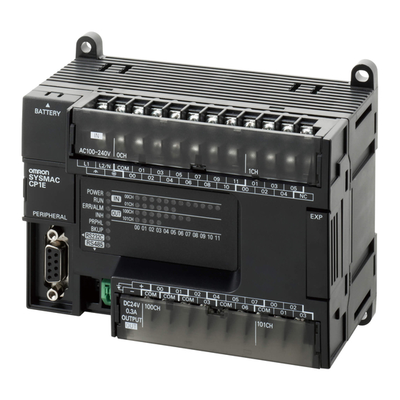
3 Part Names and Functions CPU Units This section describes the names of the CPU Unit parts and provides the I/O specifications and termi- nal arrangements. Refer to A-1 Dimensions for the dimensions, A-2 Wiring Diagrams for the wiring dia- grams. - Page 67 (14) Built-in Ethernet port for Used to connect to a personal computer for programming and monitoring -type CPU Units by the CX-Programmer for CP2E, or connect to other OMRON PLCs for data exchange. CP2E CPU Unit Hardware User’s Manual(W613)
- Page 68 3 Part Names and Functions CPU Unit Status Indicators : Not lit : Flashing : Lit Name Color Function Description POWER Green When PLC power is ON. -type POWER When PLC power is OFF. Not lit ERR/ALM Green When PLC is executing a program under RUN or MONITOR mode. Operation is stopped in PROGRAM mode or due to a fatal error.
- Page 69 3 Part Names and Functions Terminal Arrangements Input Arrangement AC Power Supply CP2E- 14D -A CIO 0 L1,L2/N : Power supply terminal L1 L2/N COM 01 : Protective ground terminal : Common terminal 00 to 07 : Input terminal : No connection CP2E- 20D -A CIO 0 L1,L2/N : Power supply terminal...
-
Page 70: E30/40/60, S30/40/60 Or N30/40/60 Cpu Units
3 Part Names and Functions 3-1-2 E30/40/60, S30/40/60 or N30/40/60 CPU Units Part Names and Functions E/S-type CPU Unit N-type CPU Unit CP2E-E30/40/60DR-A CP2E-N30/40/60D - CP2E-S30/40/60D - (6) Power supply (14) Battery holder (7) Input terminals input terminals (1) Input terminal block (8) Ground (2) Input... - Page 71 (15) Built-in Ethernet port for Used to connect to a personal computer for programming and monitoring -type CPU Units by the CX-Programmer for CP2E, or connect to other OMRON PLCs for data exchange. (16) Built-in RS-232C port for By connecting a PT, the controlled system can be monitored and data can -type CPU Units be collected.
- Page 72 3 Part Names and Functions CPU Unit Status Indicators : Not lit : Flashing : Lit Name Color Function Description POWER Green When PLC power is ON. -type POWER When PLC power is OFF. Not lit Green When PLC is executing a program under RUN or MONITOR mode. ERR/ALM Operation is stopped in PROGRAM mode or due to a fatal error.
- Page 73 3 Part Names and Functions Precautions for Safe Use Do not turn OFF the power supply to the PLC when the BKUP indicator is lit. It indicates that data is being written to the built-in Flash Memory. If the power is turned OFF during backup, the data will not be backed up and transferred to the DM Area in RAM next time the power supply is turned ON.
- Page 74 3 Part Names and Functions Output Arrangement AC Power Supply CP2E- 30D -A : External supply terminal : Common terminal 00 to 07 : Output terminal CIO 100 CIO 101 CP2E- 40D -A COM COM 07 COM CIO 100 CIO 101 CP2E- 60D -A −...
- Page 75 3 Part Names and Functions CP2E-S30DT-D COM :Common terminal 00~07 :Output terminal :External power supply input terminal COM(V-) COM for CIO 100.00/01 (DC24V) :External power supply input terminal Note COM(V-) has been connected with V- in an inner circuit. for CIO 100.00/01 (0V) CP2E-S30DT1-D COM(V+) COM CIO 100...
-
Page 76: Common I/O Specifications
3 Part Names and Functions 3-1-3 Common I/O Specifications The following table gives the specifications that apply to the built-in I/O on a CP2E CPU Unit. Specifications Item Specification High-speed counter High-speed counter inputs, interrupt inputs, Input type Normal inputs inputs or normal inputs quick-response inputs or normal inputs... - Page 77 3 Part Names and Functions Interrupt input mode Pulse plus direction input mode Increment mode Differential phase mode Up/down input mode -type: 0.00/0.01 -type: 0.00/0.01 N14/20-type: 0.00/0.01 N14/20-type: 0.00/0.01 N30/40/60-type: 0.00 to 0.02 N30/40/60-type: 0.00 to 0.03 10.0μs min. 20.0μs min. 2.5μs 2.5μs min.
- Page 78 3 Part Names and Functions Estimating the Service Life of Relays Under normal conditions, the service life of output contacts is as shown above. The service life of relays is as shown in the following diagram as a guideline. CP2E- 1000 125-VAC resistive load 30-VDC/250-VAC...
- Page 79 3 Part Names and Functions Output Specifications for Transistor Outputs (Sinking or Sourcing) CP2E- N14/20/30/40/60DT(1)- , CP2E-S30/40/60DT(1)- Normal Outputs Specification -type: CIO 100.00 and CIO 100.01 -type: CIO 100.02 to CIO 102.07 Item -type: CIO 100.00, CIO 100.01, -type: CIO 100.02 to CIO 100.07, CIO 101.00 and CIO 101.01 CIO 101.02 to CIO 102.07 Maximum...
- Page 80 3 Part Names and Functions *2 The bits that can be used depend on the model of CPU Unit. Precautions for Correct Use Precautions for Correct Use Do not connect a load to an output terminal or apply a voltage in excess of the maximum switch- ing capacity.
-
Page 81: Serial Communication Port
3 Part Names and Functions 3-1-4 Serial Communication Port The Serial Communication Port can be used for a CP2E CPU Unit. -type CPU Units CP2E S30/40/60 CPU Unit Built-in RS-232C port Built-in RS-485 port -type CPU Unit only) Built-in RS-232C Port for E/S -type CPU Units Abbr. -
Page 82: Type Cpu Units
3 Part Names and Functions -type CPU Units CP2E N -type CPU Unit Slot 2 CP1W-CIF01 CP1W-CIF11/12-V1 RS-232C RS-422A/485 Option Board Option Board Slot 1 CP1W-CIF01 CP1W-CIF11/12-V1 CP2W-CIFD1 CP2W-CIFD2 CP2W-CIFD3 RS-232C RS-422A/485 RS-232C&RS-232C RS-232C&RS-485 RS-485&RS-485 Option Board Option Board Option Board Option Board Option Board Note CP2W-CIFD... - Page 83 3 Part Names and Functions CP1W-CIF01 RS-232C Option Board Front Rear Communications status indicator CPU Unit connector COMM RS-232C connector RS-232C Connector Abbr. Signal Signal direction − Frame ground SD(TXD) Send data Output RD(RXD) Receive data Input RS(RTS) Request to send Output CS(CTS) Clear to send...
- Page 84 3 Part Names and Functions CP1W-CIF11 or CP1W-CIF12-V1 RS-422A/485 Option Board Front Rear Communications status indicator CPU Unit connector COMM DIP switch for operation RDA- RDB+ SDA- SDB+ FG settings RS-422A/485 terminal block RS-422A/485 Terminal Block Tighten screws on the terminal block to 0.28 N .
- Page 85 3 Part Names and Functions CP2W-CIFD1 RS-232C&RS-232C Option Board Front Rear Communications status indicator CPU Unit connector RS-232C&RS-232C terminal block RS-232C&RS-232C Terminal Block Port Abbr. Signal Name Signal direction PORT SD(TXD) Send data Output RD(RXD) Receive data Input − SG(0V) Signal ground −...
- Page 86 3 Part Names and Functions CP2W-CIFD2 RS-232C&RS-485 Option Board Front Rear Communications status indicator CPU Unit connector RS-232C&RS-485 terminal block DIP switch RS-232C&RS-485 Terminal Block Port Abbr. Signal Name Signal direction PORT SD(TXD) Send data Output RD(RXD) Receive data Input −...
- Page 87 3 Part Names and Functions CP2W-CIFD3 RS-485&RS-485 Option Board Front Rear Communications status indicator CPU Unit connector RS-485&RS-485 terminal block DIP switch RS-485&RS-485 Terminal Block Port Abbr. Signal Name Signal direction − PORT Send/Receive data - − Send/Receive data + −...
-
Page 88: Analog Option Board For N -Type Cpu Units
3 Part Names and Functions 3-1-5 Analog Option Board for N -type CPU Units The Analog Option Board can be used for a CP2E N -type CPU Unit. -type CPU Units CP2E N -type CPU Unit CP1W-ADB21 CP1W-DAB21V CP1W-MAB221 Analog Input Analog Output Analog Input/Output Option Board... - Page 89 3 Part Names and Functions Analog Input Option Board Analog Input Terminal Arrangement Voltage Input 1 Current Input 1 Voltage Input 2 Current Input 2 Input Common Note When using current inputs, voltage input terminals must be short-circuited with current input terminals. Main Specifications Specifications Item...
- Page 90 3 Part Names and Functions Analog Output Option Board Analog Output Terminal Arrangement Voltage Output 1 Voltage Output 2 Output Common Main Specifications Specifications Item Voltage Output Current Output Output signal range 0 V to 10 V External output allowable load resistance 2 kΩ...
- Page 91 3 Part Names and Functions Analog I/O Option Board Analog I/O Terminal Arrangement Voltage Input 1 Current Input 1 Voltage Input 2 Current Input 2 Analog I/O Common Voltage Output 1 Voltage Output 2 Analog I/O Common Note When using current inputs, voltage input terminals must be short-circuited with current input terminals. Main Specifications Specifications Item...
-
Page 92: Expansion I/O Units
3 Part Names and Functions Expansion I/O Units This section describes the names of the Expansion I/O Unit parts and provides the input specifications and terminal arrangement. Refer to A-1 Dimensions for the dimensions, A-2 Wiring Diagrams for the wiring diagrams. 3-2-1 Expansion Input Unit Part Names and Functions... -
Page 93: Expansion Output Units
3 Part Names and Functions 3-2-2 Expansion Output Units Part Names and Functions 8-point Output Units 16-point Output Units CP1W-8ER/8ET/8ET1 CP1W-16ER/ET/ET1 Output terminals Output terminals Expansion I/O Expansion I/O connecting cable connecting cable Output indicators Output indicators 00 01 02 03 04 05 06 07 Expansion connector 16ER Expansion connector... - Page 94 3 Part Names and Functions Terminal Arrangements The first word of output words allocated to the Expansion Output Unit is indicated by CIO n. 8-point Output Units (CP1W-8E ) Unit Upper Terminal Block Unit Lower Terminal Block : Common terminal 00 to 07 : Output terminal CIO n...
-
Page 95: Expansion I/O Units
3 Part Names and Functions 3-2-3 Expansion I/O Units Part Names and Functions Units with 20 I/O Points Units with 40 I/O Points CP1W-20EDR1/EDT/EDT1 CP1W-40 EDR/EDT/EDT1 Input indicators Input indicators Input terminals Input terminals Expansion I/O Expansion I/O connecting cable connecting cable Expansion connector... - Page 96 3 Part Names and Functions Terminal Arrangements The first word of input words allocated to the Expansion I/O Unit is indicated by CIO m and the first word of the output words by CIO n. 20-point I/O Units (CP1W-20ED ) •...
-
Page 97: I/O Specifications
3 Part Names and Functions 3-2-4 I/O Specifications This section describes the I/O specifications common to all Expansion I/O Units. I/O Specifications Input Specifications (CP1W-8ED/20EDR1/20EDT/20EDT1/40EDR/40EDT/40EDT1) Item Specification Input voltage 24 VDC, +10% / -15% Input impedance 4.7 kΩ Input current 5 mA typical ON voltage / current 14.4 VDC min. - Page 98 3 Part Names and Functions Output Specifications for Relay Outputs (CP1W-8ER/16ER/20EDR1/32ER/40EDR) Item Specification Maximum switching capacity 2 A 250 VAC (cosφ = 1), 2 A 24 VDC (4 A/common) Minimum switching capacity 10 mA 5 VDC Service Electrical Resistive 150,000 operations (24 VDC) life of load relay...
- Page 99 3 Part Names and Functions • CP1W-32ER’s maximum number of simultaneously ON output points is 24 (75%). Relation between Number of ON Outputs and Ambient Temperature (CP1W-32ER) Number of inputs ON simultaneously (%) Ambient temperature (˚C) According to the ambient temperature, there are restrictions on power supply voltage and output load current for the CPU Units connected with the Expansion I/O Units (CP1W-8ER/16ER/20EDR1/ 32ER/40EDR).
- Page 100 3 Part Names and Functions Output Specifications for Transistor Outputs (Sinking or Sourcing) Specification Item CP1W-40EDT CP1W-32ET CP1W-20EDT CP1W-16ET CP1W-8ET CP1W-40EDT1 CP1W-32ET1 CP1W-20EDT1 CP1W-16ET1 CP1W-8ET1 Maximum 4.5 to 30 VDC 4.5 to 30 VDC 24 VDC +10%/-5% 4.5 to 30 VDC 4.5 to 30 VDC switching 0.3 A/output...
- Page 101 Programming Device This section describes the features of the CX-Programmer used for programming and debugging PLCs, as well as how to connect the PLC with the Programming Device. 4-1 Applicable Programming Devices for CP2E ......4-2 4-2 Connecting by USB .
-
Page 102: Applicable Programming Devices For Cp2E
4 Programming Device Applicable Programming Devices for CP2E A programming device is a software application for initializing, programming, monitoring, and debug- ging PLCs. This section describes the programming device used by CP2E. Applicable Programming Devices The programming devices in the following table are used to program and monitor the CP2E Unit. CP2E CPU Units are supported by CX-One version 4.51 or higher and CX-Programmer version 9.72 or higher. - Page 103 4 Programming Device CX-Programmer The CX-Programmer is a basic software application for creating and debugging PLC programs. Ladder language Ladder Programming language ST language Programming functions Simulation CX-Programmer Debugging and Monitoring maintenance functions CPU Unit PLC Setup parameters CX-Integrator The CX-Integrator is a software application for setting up Ethernet. Routing table settings General network Network configuration...
-
Page 104: Connecting By Usb
When installing the CX-One, the installer automatically stores the USB driver for USB connections in the following directory on the OS disc drive: C:\ProgramFiles\OMRON\CX-Server\USB When the personal computer is connected to the PLC by USB cable, the personal computer automati- cally recognizes the device and the USB driver installation is started. - Page 105 4 Programming Device Restrictions on Connecting by USB The following restrictions apply to the connection of the CP2E to a computer due to the USB specifica- tions. Keep these restrictions in mind when using the USB port. • Only one CP2E CPU Unit can be connected by USB to a single personal computer. It is not possible to connect multiple CP2E CPU Units simultaneously.
-
Page 106: Connection Method With An Ethernet Port
4 Programming Device Connection Method with an Ethernet Port This section describes how to connect the CX-Programmer with the CP2E N -type CPU Unit. Connection Method Using commercially available Ethernet cable, connect the CX-Programmer to the built-in Ethernet port. Computer CX-Programmer Note ・Either PORT1A or PORT1B of the CP2E N... - Page 107 4 Programming Device Select DirectEthernetUtility from the Menu as follow. Select a target network card to connect with. Open the CX-Programmer and click the PLC button as follow. CP2E CPU Unit Hardware User’s Manual(W613)
- Page 108 4 Programming Device Select the CP1/CP2 Ethernet Online item. The user can also click the button in the Tool- bars. Select a connection type Direct connection is possible only when a PLC and a computer are connected 1:1. In other cir- cumstances, select HUB connection.
- Page 109 4 Programming Device b. Choose the Hub Connection item and click Browse button to select the PLC which user wants to connect. CP2E CPU Unit Hardware User’s Manual(W613)
- Page 110 4 Programming Device Click the Connect button to connect and then connection online is completed. CP2E CPU Unit Hardware User’s Manual(W613) 4-10...
- Page 111 4 Programming Device Normal Online To connect with a PLC via Ethernet, there are two types of hardware connections that can be used (Refer to A-6 Network Installation). These are described in the following table. Connection Type Ethernet - Direct connection Ethernet - HUB connection Connection diagram Description...
- Page 112 4 Programming Device Set Ethernet (FINS/TCP) in Network Type. Click the Settings button on the right side of Network Type. The settings in the Network Tab and in the Driver are as follow dialogue boxes. CP2E CPU Unit Hardware User’s Manual(W613) 4-12...
- Page 113 4 Programming Device Click the OK button and finish the settings of the direct connection. Then connect to the CP2E by executing the CX-Programmer’s online connection command. Ethernet - HUB connection When the Ethernet port on the computer is connected to a hub and then the CX-Programmer is placed online with a PLC through the Ethernet network, this mode can be selected as the connec- tion method.
- Page 114 4 Programming Device Set the connection type as Ethernet - HUB connection in Driver Tab. Set the target PLC’s IP Address. If do not know the target PLC’s IP address, user can click the Browse button on the right side of IP Address and it will show a dialogue box as follow.
-
Page 115: Connection Method With A Serial Port
4 Programming Device Connection Method with a Serial Port This section describes how to connect the CX-Programmer with the CP2E CPU Unit. Connection Method Connect the CX-Programmer to the serial communication port. Computer CX-Programmer D-Sub connector (9-pin, female) Recommended cable for CP1W-CIF01 D-Sub connector XW2Z-200S-CV (2 m) or... - Page 116 4 Programming Device CP2E CPU Unit Hardware User’s Manual(W613) 4-16...
-
Page 117: Installation And Wiring
Installation and Wiring This section describes how to install and wire CP2E Units. 5-1 Fail-safe Circuits ..........5-2 5-2 Installation . -
Page 118: Fail-Safe Circuits
5 Installation and Wiring Fail-safe Circuits This section describes the fail-safe circuits that must be set up outside the CP2E. Always set up safety circuits outside of the PLC to prevent dangerous conditions in the event of errors in the CP2E CPU Unit or external power supply. In particular, be careful of the following points. -
Page 119: Installation
5 Installation and Wiring Installation This section describes the environmental factors that must be considered and the installation location of each Unit. 5-2-1 Installation Location Installation Environment Do not install the Unit in the following locations. • Locations subject to ambient temperatures lower than -20ºC or higher than 60ºC. •... - Page 120 5 Installation and Wiring Not possible Accessibility for Operation and Maintenance • To ensure safe access for operation and maintenance, separate the PLC as much as possible from high-voltage equipment and moving machinery. • The PLC will be easiest to install and operate if it is mounted at a height of 1.0 to 1.6 m above the floor.
- Page 121 5 Installation and Wiring Improving Noise Resistance Leave space between the CP2E and control panel or other devices to allow adequate dissipation of heat generated by the power supply. • Do not mount the PLC in a control panel containing high-voltage equipment. •...
-
Page 122: Unit Arrangement
5 Installation and Wiring 5-2-2 Unit Arrangement This section describes how to arrange the CP2E Units. As shown in the following diagrams, Units can be arranged in one or two rows when Expansion I/O Units or Expansion Units are used. Arrangement in One Row Expansion I/O Units and Expansion Units can be installed in a side-by-side arrangement. - Page 123 5 Installation and Wiring 5-2-3 Installation This section describes how to install the CP2E. Dimensions and Installation Height Dimensions • E/S -type CPU Units 110 100 90 4- φ 4.5 • N -type CPU Units 110 100 90 4- φ 4.5 Model number CP2E- 14D - CP2E- 20D -...
-
Page 124: Installation
5 Installation and Wiring Installation Methods There are two installation methods. DIN Track Installation • Units can be mounted to PEP-50N (50 cm) or PEP-100N/100N2 (100 cm) DIN Tracks. • Units can be moved and removed easily. • The installation height in the control panel will be increased depending on the type of DIN tracks used. - Page 125 5 Installation and Wiring Fit the back of the Units onto the DIN Track by catching (1) the top of the Units on the Track and then pressing (2) in at the bottom of the Units, as shown below. DIN Track Press in all of the DIN Track mounting pins to securely lock the Units in place.
- Page 126 5 Installation and Wiring End Plate Use the PFP-M End Plates to secure the Units so that they do not move towards one end or the other of the DIN Track. Surface Installation Surface Installation • Create the mounting holes in the mounting surface as shown in the dimensions diagrams. •...
- Page 127 5 Installation and Wiring Using Wiring Ducts Whenever possible, route I/O wiring through wiring ducts. Install the ducts so that it is easy to wire the I/O Units through the ducts. It is handy to have the ducts at the same height as the Racks. Use mount- ing bases if necessary to adjust the heights.
-
Page 128: Connecting Expansion I/O Units And Expansion Units
5 Installation and Wiring 5-2-4 Connecting Expansion I/O Units and Expansion Units This section describes how to connect Expansion I/O Units and Expansion Units. Connection Methods Remove the cover from the CPU Unit’s or the Expansion I/O Unit’s expansion connector. Use a flat-head screwdriver to remove the cover from the Expansion I/O Connector. - Page 129 5 Installation and Wiring Precautions on Connecting Units The following restrictions apply to the CP-series Expansion Units and Expansion I/O Units that can be connected to CP2E CPU Units. Maximum Number of Connectable Units With an E30/40/60, S30/40/60 or N30/40/60 CPU Unit, a total of up to three Expansion I/O Units and Expansion Units can be connected to one CPU Unit.
-
Page 130: Wiring
5 Installation and Wiring Wiring This section describes wiring methods for the CPU Unit. 5-3-1 Wiring Procedure Make sure that the power supply is OFF before beginning wiring. − 1. Prepare the parts required for wiring. Prepare crimp terminals and cables for wiring. - Page 131 5 Installation and Wiring AC Power Supply Wiring • Use twisted-pair power supply cables to prevent noise from the power supply lines. Adding a 1:1 isolating transformer reduces electrical noise even further. • Consider the possibility of voltage drops and the allowable current, and always use thick power lines.
- Page 132 5 Installation and Wiring Wiring DC Power Supply and Ground 24VDC MCCB Upper Terminal Block GR:Protective ground terminal Ground to 100Ω or less • Wire a separate circuit for the power supply circuit so that there is no voltage drop from the inrush current or startup current that flows when other equipment is turned ON.
-
Page 133: I/O Wiring
5 Installation and Wiring 5-3-3 I/O Wiring I/O Wiring Precautions for Safe Use • Never apply a voltage that exceeds the input voltage for Input Units or the maximum switching capacity for Output Units. • When the power supply has positive and negative terminals, always wire them correctly. •... - Page 134 5 Installation and Wiring Example of Input Device Connections Use the following information for reference when selecting or connecting input devices. DC Input Units Connectable DC Input Devices (for DC Output Models) Two-wire, DC outputs Contact outputs CP2E CP2E Sensor power supply NPN open-collector outputs NPN current outputs...
- Page 135 5 Installation and Wiring Precautions When Connecting a Two-wire DC Sensor When using a two-wire sensor with a 24-VDC input device, check that the following conditions have been met. Failure to meet these conditions may result in operating errors. (1) Relation between voltage when the PLC is ON and the sensor residual voltage: ≤V −V (2) Relation between current when the PLC is ON and sensor control output (load cur-...
- Page 136 Programming Example In this example, the sensor’s power supply voltage is used as the input to CIO 0.00. A 100-ms timer delay (the time required for an OMRON Proximity Sensor to stabilize) is created in the program. After the Completion Flag for the timer turns ON, the sensor input on input bit CIO 0.01 will cause output bit CIO 100.00 to turn ON.
-
Page 137: Wiring Safety And Noise Controls
5 Installation and Wiring 5-3-4 Wiring Safety and Noise Controls I/O Signal Wiring Whenever possible, place I/O signal lines and power lines in separate ducts or conduits both inside and outside of the control panel. (1):I/O cables (2):Power lines Floor ducts Conduit Suspended ducts When wiring in the same duct, use shielded cables and connect the shields to the GR terminal to... -
Page 138: Relay Output Noise Reduction Methods
5 Installation and Wiring Reducing Electrical Noise for External Wiring Take the following points into account when externally wiring I/O, power supply, and power lines. • When multi-conductor signal cable is being used, do not combine I/O wires and other control wires in the same cable. - Page 139 5 Installation and Wiring Countermeasure Examples • When switching an inductive load, connect a surge protector, diodes, etc., in parallel with the load or contact as shown below. Current Circuit Characteristic Required element CR method If the load is a relay or solenoid, there is The capacitance of the capacitor must be 1 to 0.5 μF per contact current of 1 A and a time lag between the moment the cir-...
- Page 140 5 Installation and Wiring Conditions for Meeting EMC Directives when Using CP-series Relay Expansion I/O Units EN61131-2 immunity testing conditions when using the CP1W-40EDR, CP1W-32ER, or CP1W- 16ER with a CP1W-CN811 I/O Connecting Cable are given below. • Recommended Ferrite Core Ferrite Core (Data Line Filter): 0443-164151 manufactured by Nisshin Electric Minimum impedance: 90 Ω...
-
Page 141: Troubleshooting
Troubleshooting This section describes how to troubleshoot problems that may occur with a CP2E PLC. 6-1 Troubleshooting CPU Unit Errors ....... . . 6-2 6-1-1 Errors and Remedies . -
Page 142: Troubleshooting Cpu Unit Errors
6 Troubleshooting Troubleshooting CPU Unit Errors This section describes how to troubleshoot errors that occur in the CP2E CPU Units. 6-1-1 Errors and Remedies Use the following procedure when an error occurs. Error occurs Check the indicators on the front of the CPU Unit or use the CX- ·... -
Page 143: Checking Detailed Status
6 Troubleshooting Checking Error Status with the CX-Programmer Use the following procedure to read the error status. Place the CX-Programmer online with the CPU Unit. Double-click Error Log in the project tree in the main window. The PLC Errors Window will be displayed. Click the Errors Tab. The current errors will be dis- played on the Errors Tab Page. - Page 144 6 Troubleshooting Error Log Information A maximum of 20 error records will be stored in the error log. If more than 20 errors occur, the oldest error record (in A100 to A104) will be deleted and the 19 records stored in A105 to A199 will be shifted by one, with the newest record being stored in A195 to A199.
-
Page 145: Types Of Errors
6 Troubleshooting Directly Monitoring the Area where Error Log Information is Stored Connect the CX-Programmer online. Read words A100 to A199. Check the error status from the registered data. 6-1-5 Types of Errors The type of error that has occurred can be identified by checking the indicators on the front of the CPU Unit, or by using the CX-Programmer to check the error status. - Page 146 6 Troubleshooting : Not lit : Flashing : Lit Error Indicator Error information Error Operation Error code flag status (A400) ERR/ LINK/ RS-232C POWER PRPHL BKUP Error Word RS-485 − − − − − Non- 0x4101 A402.15 Executed FAL A360 Operation fatal instruction...
-
Page 147: Error Processing Flowchart
6 Troubleshooting 6-1-6 Error Processing Flowchart Confirm the error category by referring to the status of the CPU Unit indicators, investigate the cause for the error in the error tables, and take corrective actions. Problem? Check the power supply. POWER indicator lit? Not lit Refer to 6-1-7 and 6-2. -
Page 148: Fatal Errors
6 Troubleshooting 6-1-8 Fatal Errors CPU Unit Indicators : Not lit : Flashing : Lit POWER POWER POWER ERR/ALM ERR/ALM ERR/ALM — — PRPHL BKUP PRPHL BKUP — PORT1A BKUP LINK/ACT — RS-232C RS-232C PORT1B — RS-485 RS-485 LINK/ACT PORT1A —... - Page 149 6 Troubleshooting Reference Information Error flag Memory Error Flag, A401.15 Error code (A400) 80F1 Error information Memory Error Location, A403 Precautions for Correct Use Precautions for Correct Use As a memory error cannot be backed up in time due to Power OFF, it will be detected at the next Power ON.
- Page 150 6 Troubleshooting Too Many I/O Points Error The number of CP-series Expansion Units and Expansion I/O Units connected exceeds the restriction for the number of Units or words for the system configuration. Turn OFF the power supply and reconfigure the system within the restrictions. Probable cause Possible remedy The number of CP-series Expansion Units and...
- Page 151 6 Troubleshooting Probable cause Possible remedy Task Error (A295.12 turns ON) Create a task for the number stored in A294 (task number when the program fails). There is no specified interrupt task when an interrupt is generated (input interrupt, high-speed counter interrupt or scheduled interrupt.) Differentiation Overflow Error Change the operating mode to PROGRAM mode and...
- Page 152 6 Troubleshooting Error information Contents Task Number When Program Stopped This word contains the task number of the task that was being executed when program execution was stopped because of a program error. A294 Cyclic tasks: 0000 hex Interrupt tasks: 8000 to 800F hex (task 0 to 15) Program Stop Error Identification This word contains FFFF hex when the stop position is in the program Information...
- Page 153 Possible remedy ON when the built-in Ethernet stops working Cycle the power supply. The Unit may be faulty. Consult because of sum value of MAC address error or your OMRON representative. controller error. Reference Information Error flag Built-in Ethernet Stop Error, A401.04...
-
Page 154: Cpu Errors
CPU Unit Errors Probable cause Possible remedy A WDT (watchdog) error occurred in the CPU Cycle the power supply. Unit. The Unit may be faulty. Consult your OMRON representative. (This does not occur in normal use.) Reference Information − Error flag −... -
Page 155: 6-1-10 Non-Fatal Errors
6 Troubleshooting 6-1-10 Non-fatal Errors A non-fatal error has occurred if both the RUN indicator is lit and the ERR/ALM indicator is flashing during operation (i.e., in RUN or MONITOR mode). CPU Unit Indicators : Not lit : Flashing : Lit POWER POWER POWER... - Page 156 6 Troubleshooting Reference Information Error flag Backup Memory Error Flag, A315.15 Error code (A400) 00F1 − Error information PLC Setup Errors Probable cause Possible remedy A set value error occurred in the PLC Setup. Correct the PLC Setup with correct values. Reference Information Error flag PLC Setup Error Flag, A402.10...
- Page 157 6 Troubleshooting Ethernet Setting Table Error (Only for N -type CPU Units) Probable cause Possible remedy An error occurs in routing table. Set the routing table again by the CX-Integrator. An error occurs in IP address table or IP router Confirm the IP Router Table on the Built-in Ethernet Tab in table.
- Page 158 6 Troubleshooting Reference Information Error flag Built-in Ethernet Error Flag, A315.10 Other Non-fatal Flag, A402.00 Error code (A400) 03C0: FINS/TCP connection setup error 03C1: Ethernet server setup error 03C4: Ethernet server connection error Error information 03C0 Leftmost byte: FINS/TCP connection number (A313) 01: FINS/TCP connection No.1 02: FINS/TCP connection No.2...
-
Page 159: 6-1-11 Other Errors
6 Troubleshooting 6-1-11 Other Errors Communications Errors CPU Unit Indicators : Not lit : Flashing : Lit POWER POWER POWER ERR/ALM ERR/ALM ERR/ALM — — PRPHL BKUP PRPHL BKUP — PORT1A BKUP LINK/ACT RS-232C — RS-232C PORT1B — RS-485 RS-485 LINK/ACT PORT1A —... - Page 160 6 Troubleshooting Ethernet Communication Error When Ethernet Communication Error occurs during FINS communication service by built-in Ether- net port, the error code, error contents and error’s time will be stored in A40 to A44. The detail information of error code and error contents show as the following table. Error Detailed information code...
-
Page 161: Troubleshooting Unit Errors
6 Troubleshooting Troubleshooting Unit Errors This section describes how to troubleshoot errors that occur in devices other than the CP2E CPU Unit. 6-2-1 Inputs Symptom Probable cause Possible remedy Not all inputs turn ON or 1. External power is not supplied for the Supply power. -
Page 162: Outputs
6 Troubleshooting 6-2-2 Outputs Symptom Probable cause Possible remedy Not all outputs turn ON 1. Load is not supplied with power. Supply power. 2. Load voltage is low. Adjust voltage to within rated range. 3. Terminal block screws are loose. Tighten screws. -
Page 163: Cx-Programmer Connection
6 Troubleshooting 6-2-3 CX-Programmer Connection Use the following procedure if the CX-Programmer cannot connect to the PLC. Connecting via the Peripheral USB Port The CX-Programmer cannot connect. Is the USB cable Insert the cable all the way in at both the securely connected? personal computer and at the CPU Unit. - Page 164 6 Troubleshooting Connecting via the Ethernet Port The CX-Programmer cannot connect. At the personal computer (or the Ethernet switch) and the CPU Unit, firmly insert the cable until the connector locks. Confirm that the LINK/ACT Is the Ethernet cable indicator lights at the personal computer securely connected? (or Ethernet switch).
- Page 165 Maintenance and Inspection This section describes periodic inspections, the service life of the Battery, and how to replace the Battery. 7-1 Periodic Maintenance and Inspection ......7-2 7-1-1 Tools Required for Inspections .
-
Page 166: Maintenance And Inspection
7 Maintenance and Inspection Periodic Maintenance and Inspection This section describes periodic inspections and maintenance of CP2E PLCs. Daily or periodic inspections are required in order to maintain the PLC’s functions in peak operating condition. 7-1-1 Tools Required for Inspections Required Tools •... -
Page 167: Inspection And Maintenance
7 Maintenance and Inspection 7-1-3 Inspection and Maintenance Inspection Inspection Criteria Remedy points Power sup- Check for voltage fluctuations Allowable voltage Use a voltage tester to check the ply voltage at the power supply terminals. range power supply at the terminals. Take AC power supply: necessary steps to bring voltage fluc- 85 to 264 VAC... -
Page 168: Unit Replacement Precautions
• If a faulty Unit is being returned for repair, describe the problem in as much detail as possible, enclose this description with the Unit, and return the Unit to your OMRON representative. • For poor contact, take a clean cotton cloth, soak the cloth in industrial alcohol, and carefully wipe the contacts clean. -
Page 169: Replacing The Battery In N/S
7 Maintenance and Inspection Replacing the Battery in N/S -type CPU Units For CP2E N/S -type CPU Units, the clock will stop when the power is turned OFF. Mount the CP2W-BAT02 Battery (sold separately) to an N/S -type CPU Unit when using the clock function. - Page 170 7 Maintenance and Inspection Low Battery Indications The ERR/ALM indicator on the front of the CPU Unit will flash when the Battery is nearly discharged. Flashing When the ERR/ALM indicator flashes, connect the CX-Programmer and read the error messages. If a low Battery message appears on the CX-Programmer or the Battery Error Flag (A402.04) is ON, first check whether the Battery is properly connected to the CPU.
- Page 171 7 Maintenance and Inspection Replacing the Battery Use the following procedure to replace the Battery when the previous Battery has become completely discharged. Precautions for Safe Use We recommend replacing the Battery with the power OFF to prevent the CPU Unit’s sensitive internal components from being damaged by static electricity.
- Page 172 7 Maintenance and Inspection Precautions for Safe Use • You must complete this procedure within 5 minutes after turning OFF the power to the CPU Unit to ensure memory backup. If the Battery is removed for more than 5 minutes, the time will be reset to 2001-01-01 01:01:01. •...
- Page 173 Using Expansion Units and Expansion I/O Units This section describes the Analog Input Unit, Analog Output Unit, Temperature Sensor Units, CompoBus/S I/O Link Unit, and Expansion I/O Units. 8-1 Analog Input Units ..........8-2 8-1-1 Overview .
-
Page 174: Analog Input Units
8 Using Expansion Units and Expansion I/O Units Analog Input Units 8-1-1 Overview Each CP1W-AD041/CP1W-AD042 Analog Input Unit provides four analog inputs. • The analog input signal ranges are 0 to 5 V, 1 to 5 V, 0 to 10 V, -10 to +10 V, 0 to 20 mA, and 4 to 20 mA. -
Page 175: Specifications
8 Using Expansion Units and Expansion I/O Units Precautions for Safe Use Do not touch the cables during operation. Static electricity may cause operating errors. (3)Expansion Connector Connected to the next Expansion Unit or Expansion I/O Unit to enable expansion. 8-1-3 Specifications CP1W-AD041/AD042 Analog Input Units are connected to a CP2E CPU Unit. - Page 176 8 Using Expansion Units and Expansion I/O Units Analog Input Signal Ranges Analog input data is digitally converted according to the input signal range as shown below. Additional Information When the input exceeds the specified range, the A/D conversion data will be fixed at either the lower limit or upper limit.
- Page 177 8 Using Expansion Units and Expansion I/O Units When the resolution is 1/12,000, the 0 to 10 V Converted Data Hexadecimal (Decimal) range correspond to hexadecimal values 0000 to 2EE0 (0 to 12,000). The entire data range is FDA8 3138 (12600) 2EE0 (12000) to 3138 hex (-600 to 12,600).
- Page 178 8 Using Expansion Units and Expansion I/O Units 0 to 20 mA Inputs When the resolution is 1/6,000, the 0 to 20 mA Converted data range correspond to hexadecimal values 0000 to Hexadecimal (Decimal) 1770 (0 to 6,000). The range of data that can be 189C (6300) converted is FED4 to 189C hex (-300 to 6,300).
-
Page 179: Flow Of Operation
8 Using Expansion Units and Expansion I/O Units 8-1-4 Flow of Operation • Connect Analog Input Units. Connect and wire Units. • Wire to analog output devices. • Write set data to output words (n+1, n+2). Create a ladder program. •... - Page 180 8 Using Expansion Units and Expansion I/O Units Wire to analog output devices. (1) Wiring internal circuits of the CPU Unit V IN1 510 kΩ 250 Ω I IN1 Analog input 1 COM1(−) 510 kΩ V IN4 250 Ω 510 kΩ I IN4 Analog input 4 COM4(−)
- Page 181 8 Using Expansion Units and Expansion I/O Units Additional Information Refer to the following information on open circuits when using voltage inputs. Analog output device Analog output device 24 VDC For example, if connected device 2 is outputting 5 V and the same power supply is being used for both devices as shown above, approximately 1/3, or 1.6 V, will be applied to the input for input device 1.
- Page 182 8 Using Expansion Units and Expansion I/O Units Create the ladder program. (1) Allocating I/O Words Four input words and two output words are allocated from the next words following the last I/O words allocated to the CPU Unit or an existing Expansion Unit or Expansion I/O Unit. Words (m+1) to (m+4) Analog Input Unit Words (n+1), (n+2)
- Page 183 8 Using Expansion Units and Expansion I/O Units (4) Reading Analog Input Conversion Values The ladder program can be used to read the memory area words where the converted val- ues are stored. With word m as the last input word allocated to the CPU Unit or an already-connected Expansion Unit, the A/D conversion data will be output to the following words m+1 to m+4.
- Page 184 8 Using Expansion Units and Expansion I/O Units (7) Program Example Destination Analog input Input range Range code Averaging Set data word Input 1 0 to 10 V 1101 (D hex) Input 2 4 to 20 mA 1110 (E hex) Input 3 -10 to +10 V 1000 (8 hex)
- Page 185 8 Using Expansion Units and Expansion I/O Units • Example: Scaling analog input values When a 0 to 10V voltage is input to the analog input word (CIO 3) of CP1W-AD042 as 0 to 12,000, convert the value into a value between 0 and 24,000 and output the result to D200. 24,000 Scaled value...
- Page 186 8 Using Expansion Units and Expansion I/O Units C: Control word Set for “Signed Integer Data (Binary)”. Control word setting #0800: Binary numeral (0000 1000 0000 0000) The number of coordinates is 1 (m=1), so 14 13 12 11 10 9 set bit 0 to 7 to “0”...
-
Page 187: Analog Output Units
8 Using Expansion Units and Expansion I/O Units Analog Output Units 8-2-1 Overview Each CP1W-DA021 Analog Output Unit provides two analog outputs. Each CP1W-DA041/CP1W-DA042 Analog Output Unit provides four analog outputs. • The analog output signal ranges are 1 to 5 V, 0 to 10 V, -10 to +10 V, 0 to 20 mA, and 4 to 20 mA. The resolution of CP1W-DA021/DA041 is 1/6,000. -
Page 188: Specifications
8 Using Expansion Units and Expansion I/O Units • I/O Terminal Arrangement for CP1W-DA041/DA042 V OUT1 Voltage output 1 I OUT1 VOUT2 COM2 I OUT3 VOUT4 COM4 I OUT1 Current output 1 VOUT1 COM1 I OUT2 VOUT3 COM3 I OUT4 COM1 Output common 1 V OUT2... - Page 189 8 Using Expansion Units and Expansion I/O Units Model CP1W-DA021/CP1W-DA041 CP1W-DA042 Item Voltage output Current output Voltage output Current output Analog Number of analog out- CP1W-DA021: 4 outputs (4 words allocated) output puts 2 outputs (2 words allocated) section CP1W-DA041: 4 outputs (4 words allocated) Output signal range 1 to 5 V,...
- Page 190 8 Using Expansion Units and Expansion I/O Units -10 to 10 V When the resolution is 1/6,000, the hexadecimal values F448 to 0BB8 (-3000 to 3000) correspond to an analog voltage range of -10 to 10 V. The entire output range is -11 to 11 V. Specify the DA conversion data as the two’s complement if it is a negative value.
- Page 191 8 Using Expansion Units and Expansion I/O Units When the resolution is 1/12,000, the hexadecimal values 0000 to 2EE0 (0 to 12000) correspond to an analog voltage range of 0 to 10 V. The entire output range is -0.5 to 10.5 V. Specify the DA conversion data as the two's complement if it is a negative value.
-
Page 192: Flow Of Operation
8 Using Expansion Units and Expansion I/O Units When the resolution is 1/12,000, the hexadecimal values 0000 to 2EE0 (0 to 12000) correspond to an analog voltage range of 0 to 20 mA. The entire output range is 0 to 21 mA. 21 mA 20 mA 8000... - Page 193 8 Using Expansion Units and Expansion I/O Units Writing Set Data and Writing D/A Conversion Data CP1W-DA021 Analog Output Unit CPU Unit Word (n+1) Set data (outputs 1, 2) Ladder program Word (n+1) Analog output 1 conversion value Analog devices Word (n+2) Analog output 2 conversion value •...
- Page 194 8 Using Expansion Units and Expansion I/O Units Wire to analog input devices. (1) Wiring internal circuits of the CPU Unit The following diagram shows the internal circuit using CP1W-DA041/DA042 as an example, which wires analog outputs 1 to 4. In the case of CP1W-DA021, analog outputs 1 to 2 can be used.
- Page 195 8 Using Expansion Units and Expansion I/O Units Create the ladder program. (1) Allocating Output Words Four output words (n+1 to n+4) are allocated to the Analog Output Unit starting from the next word following the last word allocated to the CPU Unit or previous Expansion Unit or Expansion I/O Unit.
- Page 196 8 Using Expansion Units and Expansion I/O Units (3) Writing Analog Output Conversion Values The ladder program can be used to write conversion data to the output words. When “n” is the last output word allocated to the CPU Unit, or previous Expansion Unit or Expansion I/O Unit, the output words will be n+1 to n+2 for CP1W-DA021 and n+1 to n+4 for CP1W-DA041/DA042.
- Page 197 8 Using Expansion Units and Expansion I/O Units (6) Program Example (CP1W-DA041/DA042) Analog output Output range Range code Set data Destination word Output 1 0 to 10 V 1001 (9 hex) Output 2 4 to 20 mA 1100 (C hex) Output 3 -10 to 10 V 1000 (8 hex)
- Page 198 8 Using Expansion Units and Expansion I/O Units • Example: Scaling analog output values Convert a value between 200 and 500 in D300 into 2 to 5 V to output the voltage from the analog output word (CIO 102) of CP1W-DA042. Unscaled data (200 to...
-
Page 199: Analog I/O Units
8 Using Expansion Units and Expansion I/O Units Analog I/O Units 8-3-1 CP1W-MAD11 Analog I/O Units Overview Each CP1W-MAD11 Analog I/O Unit provides 2 analog inputs and 1 analog output. • The analog input range can be set to 0 to 5 V, 1 to 5 V, 0 to 10 V, -10 to 10 V, 0 to 20 mA, or 4 to 20 mA. - Page 200 8 Using Expansion Units and Expansion I/O Units Precautions for Safe Use Do not touch the cables during operation. Static electricity may cause operating errors. (3)Expansion Connector Used for connecting Expansion Units or Expansion I/O Units. (4)DIP Switch Used to enable or disable averaging. Pin 1: Average processing for analog input 0 (OFF: Average processing not performed;...
- Page 201 8 Using Expansion Units and Expansion I/O Units Model CP1W-MAD11 Item Voltage I/O Current I/O Analog Number of analog inputs 2 inputs (2 words allocated) Input Input signal range 0 to 5 V, 1 to 5 V, 0 to 10 V, 0 to 20 mA or 4 to 20 mA Section or -10 to 10 V...
- Page 202 8 Using Expansion Units and Expansion I/O Units Analog Input Signal Ranges -10 to 10 V Voltages in the -10 to 10 V range corre- Converted Data spond to hexadecimal values F448 to 0BB8 Hexadecimal (Decimal) (-3,000 to 3,000). The range of data that can 0CE4 (3300) be converted is F31C to 0CE4 hex (-3,300 to 3,300).
- Page 203 8 Using Expansion Units and Expansion I/O Units 1 to 5 V Voltages in the 1 to 5 V range correspond to Converted Data hexadecimal values 0000 to 1770 (0 to Hexadecimal (Decimal) 6,000). The range of data that can be con- 189C (6300) verted is FED4 to 189C hex (-300 to 6,300).
- Page 204 8 Using Expansion Units and Expansion I/O Units Analog Output Signal Ranges -10 to 10 V The hexadecimal values F448 to 0BB8 (-3000 to 3000) correspond to an analog voltage range of -10 to 10 V. The entire output range is -11 to 11V. Specify the DA conversion data as the two’s complement if it is a negative value.
- Page 205 8 Using Expansion Units and Expansion I/O Units 0 to 20 mA The hexadecimal values 0000 to 1770 (0 to 6000) correspond to an analog current range of 0 to 20 mA. The entire output range is 0 to 21 mA. 21 mA 20 mA 8000...
- Page 206 8 Using Expansion Units and Expansion I/O Units Flow of Operation • Connect the Analog I/O Unit. Connect the Unit. • Set analog inputs as voltage or current inputs and set the averag- ing function. • Connect analog I/O devices. Wire the analog I/O.
- Page 207 8 Using Expansion Units and Expansion I/O Units Connect the Analog I/O Unit to the CPU Unit. CP1W-MAD11 CP2E CPU Unit Analog I/O Unit • Setting the Averaging Function DIP switch pins 1 and 2 are used to set the averaging function. When averaging is enabled, a moving average of the last eight input values is output as the converted value.
- Page 208 8 Using Expansion Units and Expansion I/O Units (3) Wiring analog input devices to the Analog I/O Unit 2-core shielded 2-core shielded twisted-pair cable twisted-pair cable V OUT Analog V OUT Analog device device Analog Analog I OUT I OUT with with Output...
- Page 209 8 Using Expansion Units and Expansion I/O Units • If the same power supply is being used by the connected devices and a disconnection occurs at points A or B in the above diagram, an unwanted circuit path will occur as shown along the dotted line in the diagram.
- Page 210 8 Using Expansion Units and Expansion I/O Units 7 6 5 4 3 2 1 0 0 0 0 0 0 word n+1 Analog Analog Analog output input 1 input 0 Example: The following instructions set analog input 0 to 4 to 20 mA, analog input 1 to 0 to 10 V, and the analog output to -10 to 10 V.
- Page 211 8 Using Expansion Units and Expansion I/O Units (6) Handling Unit Errors • When an error occurs in the Analog I/O Unit, analog input data will be 0000 and 0 V or 0 mA will be output as the analog output. If a CPU error or an I/O bus error (fatal errors) occurs at the CPU Unit and the analog output is set to 1 to 5 V or 4 to 20 mA, 0 V or 0 mA will be output.
-
Page 212: Cp1W-Mad42/Cp1W-Mad44 Analog I/O Units
8 Using Expansion Units and Expansion I/O Units 8-3-2 CP1W-MAD42/CP1W-MAD44 Analog I/O Units Overview Each CP1W-MAD42 Analog I/O Unit provides 4 analog inputs and 2 analog outputs. Each CP1W-MAD44 Analog I/O Unit provides 4 analog inputs and 4 analog outputs. •... - Page 213 8 Using Expansion Units and Expansion I/O Units • Output Terminal Arrangement for CP1W-MAD42 V OUT1 Voltage output 1 I OUT1 Current output 1 COM1 Output common 1 V OUT2 Voltage output 2 I OUT2 Current output 2 COM2 Output common 2 •...
- Page 214 8 Using Expansion Units and Expansion I/O Units Model CP1W-MAD42/CP1W-MAD44 Item Voltage I/O Current I/O Analog Number of inputs 4 inputs (4 words allocated) Input Input signal range 0 to 5 VDC, 1 to 5 VDC, 0 to 20 mA or 4 to 20 mA Section 0 to 10 VDC, or −10 to 10 VDC ±15 V...
- Page 215 8 Using Expansion Units and Expansion I/O Units Analog Input Signal Ranges −10 to 10 V The −10 to 10 V range corresponds to the hexadecimal values E890 to 1770 (−6000 to 6000). The entire data range is E638 to 19C8 (−6600 to 6600). A negative voltage is expressed as a two’s complement.
- Page 216 8 Using Expansion Units and Expansion I/O Units 1 to 5 V The 1 to 5 V range corresponds to the hexadecimal values 0000 to 2EE0 (0 to 12000). The entire data range is FDA8 to 3138 (−600 to 12600). Inputs between 0.8 and 1 V are expressed as two’s complements.
- Page 217 8 Using Expansion Units and Expansion I/O Units Analog Output Signal Ranges −10 to 10 V The hexadecimal values E890 to 1770 (−6000 to 6000) correspond to an analog voltage range of −10 to 10 V. The entire output range is −11 to 11 V. Specify a negative voltage as a two’s complement. 11 V 10 V E638...
- Page 218 8 Using Expansion Units and Expansion I/O Units 0 to 20 mA The hexadecimal values 0000 to 2EE0 (0 to 12000) correspond to an analog current range of 0 to 20 mA. The entire output range is 0 to 21 mA. 21 mA 20 mA 8000...
- Page 219 8 Using Expansion Units and Expansion I/O Units Flow of Operation • Connect the Analog I/O Unit. Connect the Unit. • Set analog inputs as voltage or current inputs and set the averag- ing function. • Connect analog I/O devices. Wire the analog I/O.
- Page 220 8 Using Expansion Units and Expansion I/O Units Writing D/A Conversion Data CPU Unit CP1W-MAD42 Ladder program Analog output 1 Word (n+1) conversion value Analog output 2 Word (n+2) conversion value Writes the conversion values. Analog devices • Adjustment equipment “n”...
- Page 221 8 Using Expansion Units and Expansion I/O Units Wire to analog I/O devices. (1) Wiring internal circuits of the CPU Unit Analog Inputs V IN1 510 kΩ 250 Ω I IN1 Analog input 1 COM1 (−) 510 kΩ V IN4 250 Ω...
- Page 222 8 Using Expansion Units and Expansion I/O Units Precautions for Correct Use Precautions for Correct Use • Do not connect the shield when using shielded twisted-pair cables. • When an input is not being used, short V IN and I IN to COM terminals. •...
- Page 223 8 Using Expansion Units and Expansion I/O Units Additional Information When external power is supplied (when setting the range code), or when there is a power inter- ruption, a pulse-form analog output may be generated. If this causes problems with operation, take countermeasures such as those suggested below. (1) Countermeasure 1 •...
- Page 224 8 Using Expansion Units and Expansion I/O Units (b) CP1W-MAD44 Write the set data to words (n+1 to n+4). A/D or D/A conversion begins when the set data is transferred from the CPU Unit to the Analog I/O Unit. Setting contents are shown as the following table.
- Page 225 8 Using Expansion Units and Expansion I/O Units (3) Averaging Set whether averaging is to be used for set data. When the averaging bit is set to 1, the average (moving average) for the past eight inputs is output as conversion data. (4) Reading Analog Input Converted Values Read the conversion value storage area with the ladder program.
- Page 226 8 Using Expansion Units and Expansion I/O Units This programming example uses these ranges: (a) CP1W-MAD42 Analog Input Range Averaging Set data Destination input range code word Input 1 4 to 20 mA 1110 (E hex) Input 2 0 to 10 V 1101 (D hex) Input 3 0 to 5 V...
- Page 227 8 Using Expansion Units and Expansion I/O Units Always ON Flag P_On 0005 #0002 Execution T0005 condition ← Reads analog input 1’s of CP1W-MAD42 converted value. Execution T0005 condition ← Reads analog input 2’s of CP1W-MAD42 converted value. Execution T0005 condition ←...
-
Page 228: Temperature Sensor Units
8 Using Expansion Units and Expansion I/O Units Temperature Sensor Units 8-4-1 CP1W-TS 1/TS 2 Temperature Sensor Units Overview CP1W-TS002/TS102 Temperature Sensor Units each provide up to four input points, and CP1W- TS001/TS101 Temperature Sensor Units each provide up to two input points. The inputs can be from thermocouples or platinum resistance thermometers. - Page 229 8 Using Expansion Units and Expansion I/O Units Specifications A CP1W-TS 01/TS 02 Temperature Sensor Unit can be connected to a CP2E CPU Unit. CP1W-20EDR1 CP1W-8ED CP1W-TS 01/TS CP2E CPU Unit Expansion I/O Unit Expansion I/O Unit Temperature Sensor Unit C OM C OM 00 01 02 03 04 05 06 07...
- Page 230 8 Using Expansion Units and Expansion I/O Units Flow of Operation • Connect the Temperature Sensor Units to the CPU Unit. Connect the Temperature Sensor Units. • Set the temperature unit, 2-decimal-place mode if required, and Set the temperature ranges. set the temperature input range.
- Page 231 8 Using Expansion Units and Expansion I/O Units Precautions for Correct Use Precautions for Correct Use Always turn OFF the power supply before setting the temperature range. DIP Switch Rotary Switch Used to set the temperature Used to set the unit and the number of temperature input range.
- Page 232 8 Using Expansion Units and Expansion I/O Units Connect Temperature Sensors. (1) Thermocouples (a) CP1W-TS001 Either K or J thermocouples can be connected to the CP1W-TS001, but both thermocouples must be the same type and the same input range. Input 0 Input 1 Input 0 Input 1...
- Page 233 8 Using Expansion Units and Expansion I/O Units (2) Platinum Resistance Thermometers (a) CP1W-TS101 One or two Pt or JPt platinum resistance thermometers can be connected to the CP1W-TS101, but both of the thermometers must be of the same type and the same input range must be used for each.
- Page 234 8 Using Expansion Units and Expansion I/O Units Create the ladder program. (1) Words Allocation Temperature Sensor Units are allocated words in the same way as other CP-series Expan- sion Units or Expansion I/O Units, i.e., in order of connection. A Temperature Sensor Unit is allocated the next input words following the input words of the CPU Unit or previous Expan- sion Unit or Expansion I/O Unit.
- Page 235 8 Using Expansion Units and Expansion I/O Units • If the converted value is a negative value, it will be stored as its two’s complements. • Data for range codes that include one digit after the decimal point are stored as binary without the decimal point, i.e., 10 times the actual value is stored.
- Page 236 8 Using Expansion Units and Expansion I/O Units Always ON P_On Detects completion of input 0 initialization. #7FFE P_EQ W0.00 ON when input 0 has been initialized Always ON P_On Detects completion of input 1 initialization. #7FFE P_EQ W0.01 ON when input 1 has been initialized W0.00 Execution condition Detects an open-circuit alarm or Unit...
- Page 237 8 Using Expansion Units and Expansion I/O Units (b) The following programming example shows how to convert the data for tempera- ture input 0 to BCD and store the result in D0 and D1. “#0001” is stored in D1 when the input data is a negative value. The following system configuration is used.
- Page 238 8 Using Expansion Units and Expansion I/O Units (7) Programming with SCL2 Instruction Always ON P_On Detects completion of input 0 initialization. #7FFE P_EQ ON when initialization complete. W0.00 Execution W0.00 condition Detects an open-circuit alarm or Unit error by checking whether the error code 7FFF has been output #7FFF P_EQ...
- Page 239 8 Using Expansion Units and Expansion I/O Units Temperature Data Partitioning and Structure Temperature Data (Actual Temperature x 100 Binary) @ @ @ @ @ @ Leftmost 3 Digits and Flags Temperature Open-circuit Leftmost/ Not used. Temperature data Unit Flag Flag Rightmost Flag 0: °C...
- Page 240 8 Using Expansion Units and Expansion I/O Units Example 2 Temperature: -100.12°C ×100: -10012 Temperature Data: FFD8E4 (hexadecimal for -10012) Leftmost 3 Digits and Flags ×16 ×16 ×16 Flags Bits 11 to 08 07 to 04 03 to 00 Data Normal Temperature Flags...
- Page 241 8 Using Expansion Units and Expansion I/O Units Additional Information • Leftmost digits are stored in the lower memory addresses. Treat the data in the lower memory address as the leftmost digits when programming. • Be sure that the data is read at least once every 125 ms to allow for the CPU Unit’s cycle time and communications time.
- Page 242 8 Using Expansion Units and Expansion I/O Units A200.11 (First Scan Flag) Sets D103 and D102 to #0100 and #0000 #0000, respectively. D102 #0100 D103 P_On (Always ON Flag) Detects completion of input 0 initialization. #7FFE P_EQ W0.00 ON when input 0 has been initialized. W0.00 2.13 (open-circuit detected)
-
Page 243: Cp1W-Ts003 Temperature Sensor Units
8 Using Expansion Units and Expansion I/O Units Description of Operation CIO 2: Leftmost 3 digits of temperature data CIO 2: Rightmost 3 digits of temperature data W100 W102 0 16 W101 If the temperature data is non-negative, binary data is converted to BCD data. - Page 244 8 Using Expansion Units and Expansion I/O Units (3)Expansion I/O Connecting Cable Connected to the expansion connector of a CP2E CPU Unit or an Expansion Unit or Expansion I/O Unit.The cable is included with the Temperature Sensor Unit and cannot be removed. Precautions for Safe Use Do not touch the cables during operation.
- Page 245 8 Using Expansion Units and Expansion I/O Units Analog Input Signal Ranges Analog input data is digitally converted according to the input signal range as shown below. Additional Information When the input exceeds the specified range, the A/D conversion data will be fixed at either the lower limit or upper limit.
- Page 246 8 Using Expansion Units and Expansion I/O Units 4 to 20 mA The 4 to 20 mA range corresponds to the hexadecimal values 0000 to 2EE0 (0 to 12000). The entire data range is FDA8 to 3138 (−600 to 12600). Inputs between 3.2 and 4 mA are expressed as two’s complements.
- Page 247 8 Using Expansion Units and Expansion I/O Units Connect the Temperature Sensor Unit to the CPU Unit. CP2E CPU Unit CP1W-20EDR1 CP1W-8ED CP1W-TS003 Expansion I/O Unit Expansion I/O Unit Temperature Sensor Unit C O M C O M 00 01 02 03 04 05 06 07 C H 00 01 02 03 08 09 10 11 08 09 10 11...
- Page 248 8 Using Expansion Units and Expansion I/O Units With the Temperature Sensor Unit’s DIP switch, set the input type (temperature or analog input), the input thermocouple type (K or J) and the temperature unit (°C or °F). SW 1 Setting Thermocouple type of temperature sensor Temperature unit...
- Page 249 8 Using Expansion Units and Expansion I/O Units Precautions for Correct Use Precautions for Correct Use When connecting a thermocouple input, observe the following precautions: • Do not remove the cold junction compensator attached at the time of delivery. If the cold junc- tion compensator is removed, the Unit will not be able to measure temperatures correctly.
- Page 250 8 Using Expansion Units and Expansion I/O Units Create the ladder program. (1) Word Allocations Temperature Sensor Units are allocated words in the same way as other CP-series Expan- sion Units or Expansion I/O Units, in order of connection. A Temperature Sensor Unit is allocated the next input words following the input words of the CPU Unit or previous Expan- sion Unit or Expansion I/O Unit.
- Page 251 8 Using Expansion Units and Expansion I/O Units (4) Programming Example The following programming example shows how to store the input data of CP1W-TS003 (4 inputs) in D0 to D3, and W10.00 to W10.03 turn ON at the time of open-circuit detection. CP2E CP1W-TS003 Temperature Sensor Unit...
- Page 252 8 Using Expansion Units and Expansion I/O Units Detects initialization complete <>(305) MOV(021) Stores input 0’s data in D0. #7FFE ON when an open-circuit alarm has been W10.00 =(300) detected for thermocouples input 2. #7FFF <>(305) MOV(021) Stores input 1’s data in D1. #7FFE ON when an open-circuit alarm has been W10.01...
-
Page 253: Ts004 Temperature Sensor Units
8 Using Expansion Units and Expansion I/O Units 8-4-3 TS004 Temperature Sensor Units Overview CP1W-TS004 Temperature Sensor Unit provide up to twelve input points. The inputs can be from thermocouples. CP1W-TS004 Temperature Sensor Unit is allocated two input words and one output word, so no more than seven Units can be connected. - Page 254 8 Using Expansion Units and Expansion I/O Units Specifications Item CP1W-TS004 Temperature sensors Thermocouples Switchable between K and J, but same type must be used for all inputs. Number of inputs Allocated input words Allocated output words Accuracy 25°C (The larger of ±0.5% of converted value or ±2°C) ±1 digit max. *1 0 to 60°C (The larger of ±1% of converted value or ±4°C) ±1 digit max.
- Page 255 8 Using Expansion Units and Expansion I/O Units Set temperature ranges. Precautions for Safe Use Do not touch the DIP switch while power is being supplied. Static electricity may cause operating errors. Precautions for Correct Use Precautions for Correct Use Always turn OFF the power supply before setting the temperature range.
- Page 256 8 Using Expansion Units and Expansion I/O Units Connecte Temperature Sensors. (1) Thermocouples Either K or J thermocouples can be connected, but all twelve thermocouples must be the same type and the same input range. Temperature input 1 Cold junction Temperature input 11 compensator Temperature input 0...
- Page 257 8 Using Expansion Units and Expansion I/O Units (2) Reading Temperature Data There are 12 temperature input data to be read, but only two input words are allocated to CP1W-TS004. The operation is shown as the following. • Input Word Response.
- Page 258 8 Using Expansion Units and Expansion I/O Units (3) Creating Ladder Program (1) Write temperature data command Write temperature data command which read temperature data from input word to CIO n+1. (2) Response confirmation After CP1W-TS004 receives CIO n+1 read command and CP1W-TS004’s internally specified input temperature data is ready, the value which is the same as the read com- mand will be stored in CIO m+1.
- Page 259 8 Using Expansion Units and Expansion I/O Units (4) Programming Example The temperature data of CP1W-TS004 (12 inputs, input type is J type and temperature unit is °C) is stored in D0 to D11. When it occurs open-circuit alarm, W10.00 to W10.11 is ON. CP2E CP1W-TS004 Temperature Sensor Unit...
- Page 260 8 Using Expansion Units and Expansion I/O Units First Cycle ON Flag Start to read temperature data. W0.00 W0.00 MOV(021) Write input 0’s read command (#9901) to CIO 102 (CIO n+1). #9901 If CIO 2 (CIO m+1) and read MOV(021) =(300) command are matched, store #9901...
- Page 261 8 Using Expansion Units and Expansion I/O Units W0.03 MOV(021) #9904 MOV(021) =(300) #9904 Read Input 3’s temperature data W10.03 =(300) #7FFF W0.04 RSET W0.03 W0.04 MOV(021) #9905 MOV(021) =(300) #9905 Read Input 4’s temperature data W10.04 =(300) #7FFF W0.05 RSET W0.04 W0.05...
- Page 262 8 Using Expansion Units and Expansion I/O Units W0.06 MOV(021) #9907 MOV(021) =(300) #9907 Read Input 6’s temperature data W10.06 =(300) #7FFF W0.07 RSET W0.06 W0.07 MOV(021) #9908 MOV(021) =(300) #9908 Read Input 7’s temperature data W10.07 =(300) #7FFF W0.08 RSET W0.07 W0.08...
- Page 263 8 Using Expansion Units and Expansion I/O Units W0.09 MOV(021) #990A MOV(021) =(300) #990A Read Input 9’s temperature data W10.09 =(300) #7FFF W0.10 RSET W0.09 W0.10 MOV(021) #990B MOV(021) =(300) #990B Read Input 10’s temperature data W10.10 =(300) #7FFF W0.11 RSET W0.10 W0.11...
- Page 264 8 Using Expansion Units and Expansion I/O Units CP2E CPU Unit Hardware User’s Manual(W613) 8-92...
-
Page 265: Appendices
Appendices A-1 Dimensions ..........A-2 A-1-1 CPU Units . -
Page 266: Dimensions
Appendices Dimensions A-1-1 CPU Units CPU Units with 14 or 20 I/O Points CP2E-N14/20D - Unit: mm CP2E-E14/20D - Unit: mm CP2E CPU Unit Hardware User’s Manual(W613) - Page 267 Appendices CPU Units with 30 I/O Points CP2E-N30D - Unit: mm CP2E-E30D - , CP2E-S30D - Unit: mm CPU Units with 40 I/O Points CP2E-N40D - Unit: mm CP2E CPU Unit Hardware User’s Manual(W613)
- Page 268 Appendices CP2E-E40D - , CP2E-S40D - Unit: mm CPU Units with 60 I/O Points CP2E-N60D - Unit: mm CP2E-E60D - , CP2E-S60D - Unit: mm CP2E CPU Unit Hardware User’s Manual(W613)
-
Page 269: A-1-2 Option Boards
Appendices A-1-2 Option Boards CP1W-CIF01 RS-232C Option Board Unit: mm 0.15 16.5 35.9 13.5 16.5 19.7 CP1W-CIF11/CIF12-V1 RS-422A/485 Option Board Unit: mm 0.15 16.5 35.9 13.5 15.7 16.5 CP2W-CIFD1 RS-232C & RS-232C Option Board Unit: mm 0.15 3.75 36.4 CP2E CPU Unit Hardware User’s Manual(W613) - Page 270 Appendices CP2W-CIFD2 RS-232C & RS485 Option Board Unit: mm 0.15 3.75 36.4 CP2W-CIFD3 RS-485 & RS-485 Option Board Unit: mm 0.15 3.75 36.4 CP1W-MAB221 Analog Input/Output Option Board Unit: mm 0.15 36.4 CP2E CPU Unit Hardware User’s Manual(W613)
- Page 271 Appendices CP1W-ADB21 Analog Input Option Board Unit: mm 0.15 36.4 CP1W-DAB21V Analog Output Option Board Unit: mm 0.15 36.4 CP2E CPU Unit Hardware User’s Manual(W613)
-
Page 272: A-1-3 Expansion I/O Units
Appendices A-1-3 Expansion I/O Units CP1W-8ED Expansion I/O Unit with 8 Input Points Unit: mm 100±0.2 56±0.2 2-φ4.5 CP1W-8E Expansion I/O Units with 8 Output Points Unit: mm 90 100±0.2 56±0.2 2-φ4.5 CP1W-16E Expansion I/O Units with 16 Output Points Unit: mm 90 100±0.2 76±0.2... - Page 273 Appendices CP1W-32ER/ET/ET1 Expansion I/O Units with 32 Output Points Unit: mm 110 100 90 4-φ4.5 CP1W-20ED Expansion I/O Units with 20 I/O Points Unit: mm 90 100±0.2 76±0.2 2-φ4.5 CP1W-40ED Expansion I/O Units with 40 I/O Points Unit: mm 110 100 90 4-φ4.5 CP2E CPU Unit Hardware User’s Manual(W613)
-
Page 274: A-1-4 Expansion Units
Appendices A-1-4 Expansion Units CP1W-MAD11/MAD42/MAD44 Analog I/O Units Unit: mm 90 100±0.2 76±0.2 2-φ4.5 CP1W-AD041/AD042 Analog Input Unit Unit: mm 90 100±0.2 76±0.2 2-φ4.5 CP1W-DA021/DA041/DA042 Analog Output Unit Unit: mm 90 100±0.2 76±0.2 2-φ4.5 CP2E CPU Unit Hardware User’s Manual(W613) A-10... - Page 275 Appendices CP1W-TS 1/2/3 Temperature Sensor Units Unit: mm 100±0.2 76±0.2 CP1W-TS004 Temperature Sensor Units Unit: mm 90 100±0.2 Two,4.5 dia. 140 ± 0.2 140 ± 0.2 holes CP2E CPU Unit Hardware User’s Manual(W613) A-11...
-
Page 276: Wiring Diagrams
Appendices Wiring Diagrams A-2-1 CPU Units CPU Unit with 14 I/O Points (Terminal Block is not removable) Input Wiring Diagram Output Wiring Diagram All Models Relay Outputs AC Power Supply CP2E-E14DR-A CP2E-E14DR-A CP2E-N14DR- CP2E-N14D -A CIO 100 DC Power Supply CP2E-N14D CIO 0 COM COM NC COM NC COM NC... - Page 277 Appendices CPU Unit with 20 I/O Points (Terminal Block is not removable) Input Wiring Diagram Output Wiring Diagram All Models Relay Outputs AC Power Supply CP2E-E20DR-A CP2E-E20DR-A CP2E-N20DR- CP2E-N20D -A CIO 100 DC Power Supply CP2E-N20D CIO 0 COM COM NC COM NC COM 06 24V DC L1 L2/N COM 01 CIO 100...
- Page 278 Appendices CPU Units with 30 I/O Points (Terminal Block is not removable) Input Wiring Diagram Output Wiring Diagram All Models Relay Outputs AC Power Supply CP2E-E30DR-A, CP2E-S30DR-A, CP2E-N30DR- CP2E-E30DR-A, CP2E-S30DR-A, CIO 100 CIO 101 CP2E-N30D -A DC Power Supply CP2E-S30D -D, CP2E-N30D CIO 0 CIO 1...
- Page 279 Appendices CPU Units with 40 I/O Points (Terminal Block is not removable) Input Wiring Diagram Output Wiring Diagram All Models Relay Outputs AC Power Supply CP2E-E40DR-A, CP2E-S40DR-A, CP2E-N40DR- CP2E-E40DR-A, CP2E-S40DR-A, CIO 100 CIO 101 CP2E-N40D -A DC Power Supply CP2E-S40D -D, CP2E-N40D CIO 0 CIO 1...
- Page 280 Appendices CPU Units with 60 I/O Points (Terminal Block is not removable) Input Wiring Diagram Output Wiring Diagram All Models Relay Outputs AC Power Supply CP2E-E60DR-A, CP2E-S60DR-A, CP2E-N60DR- CIO 100 CIO 101 CIO 102 CP2E-E60DR-A, CP2E-S60DR-A, CP2E-N60D -A DC Power Supply COM COM COM COM 06 CP2E-S60D...
- Page 281 Appendices Input Wiring Example When Using External Power Supply AC-power-supply CPU Units with 30, 40 or 60 I/O points have an external power supply (DC24V 0.3A), and can be used as a service power supply for input devices. DC-power-supply CPU Units with 14 or 20 I/O points have no external power supply. Wiring Example: AC-power-supply CPU Units with 40 I/O Points Input device L2/N...
-
Page 282: A-2-2 Expansion I/O Units
Appendices A-2-2 Expansion I/O Units The first input word allocated to the Expansion I/O Unit is shown as CIO m and the first output word is shown as CIO n. 8-point Input Unit (Terminal Block is not removable) Input Wiring Diagram Output Wiring Diagram Outputs not provided. - Page 283 Appendices Input Wiring Diagram Output Wiring Diagram Inputs not provided. Transistor Outputs (Sinking) CP1W-8ET Unit Upper Terminal Block Unit Lower Terminal Block 4.5 to 30 VDC CIO n 4.5 to 30 VDC Transistor Outputs (Sourcing) CP1W-8ET1 Unit Upper Terminal Block Unit Lower Terminal Block 4.5 to 30 VDC CIO n...
- Page 284 Appendices Input Wiring Diagram Output Wiring Diagram Inputs not provided. Unit Lower Terminal Block CIO n+1 Transistor Outputs (Sinking) CP1W-16ET Unit Upper Terminal Block COM COM COM CIO n Unit Lower Terminal Block CIO n+1 Transistor Outputs (Sourcing) CP1W-16ET1 Unit Upper Terminal Block COM COM COM CIO n CP2E CPU Unit Hardware User’s Manual(W613)
- Page 285 Appendices Input Wiring Diagram Output Wiring Diagram Inputs not provided. Unit Lower Terminal Block CIO n+1 32-point Output Units (Terminal Block is not removable) Input Wiring Diagram Output Wiring Diagram Inputs not provided. Relay Outputs CP1W-32ER Unit Upper Terminal Block CIO n+1 CIO n COM COM...
- Page 286 Appendices Input Wiring Diagram Output Wiring Diagram Inputs not provided. Transistor Outputs (Sinking) CP1W-32ET Unit Upper Terminal Block CIO n CIO n+1 COM COM COM COM CIO n CIO n+1 Unit Lower Terminal Block CIO n+2 CIO n+3 COM COM COM CIO n+2 CIO n+3 Transistor Outputs (Sourcing)
- Page 287 Appendices Input Wiring Diagram Output Wiring Diagram Inputs not provided. Unit Lower Terminal Block CIO n+2 CIO n+3 CIO n+2 CIO n+3 20-point I/O Units (Terminal Block is not removable) Input Wiring Diagram Output Wiring Diagram All Models Relay Outputs CP1W-20EDR1 CIO m 24V DC...
- Page 288 Appendices Input Wiring Diagram Output Wiring Diagram Transistor Outputs (Sourcing) CP1W-20EDT1 CIO n 40-point I/O Units (Terminal Block is not removable) Input Wiring Diagram Output Wiring Diagram All Models Relay Outputs CP1W-40EDR CIO m CIO m+1 CIO n CIO n+1 24V DC NC 00 NC NC...
-
Page 289: Expansion Units
Appendices A-2-3 Expansion Units CP1W-AD041/AD042 Analog Input Unit (Terminal Block is not removable) Wiring Diagrams Input Terminal Arrangement V IN1 Voltage input 1 I IN1 Current input 1 COM1 Input common 1 V IN2 Voltage input 2 I IN2 Current input 2 COM2 Input common 2 V IN3... - Page 290 Appendices CP1W-DA021 Analog Output Unit (Terminal Block is not removable) Wiring Diagrams Output Terminal Arrangement V OUT1 Voltage output 1 I OUT1 Current output 1 I OUT1 VOUT2 COM2 COM1 Output common 1 VOUT1 COM1 I OUT2 V OUT2 Voltage output 2 I OUT2 Current output 2 COM2...
- Page 291 Appendices CP1W-DA041/DA042 Analog Output Unit (Terminal Block is not removable) Wiring Diagrams Output Terminal Arrangement V OUT1 Voltage output 1 I OUT1 Current output 1 COM1 Output common 1 V OUT2 Voltage output 2 I OUT2 Current output 2 COM2 Output common 2 V OUT3 Voltage output 3...
- Page 292 Appendices CP1W-MAD11 Analog I/O Unit (Terminal Block is not removable) Wiring Diagrams I/O Terminal Arrangement V OUT Voltage output I OUT Current output Output common V IN0 Voltage input 0 I IN0 Current input 0 COM0 Input common 0 V IN1 Voltage input 1 I IN1 Current input 1...
- Page 293 Appendices Wiring Diagrams Example: I OUT V IN0 COM0 IIN1 VOUT I IN0 V IN1 COM1 Connection to input for voltage output Voltage input – Connection to input 0 for voltage input Voltage output – Connection to input 1 for current input Current output –...
- Page 294 Appendices CP1W-MAD42 Analog I/O Unit (Terminal Block is not removable) Wiring Diagrams I/O Terminal Arrangement • Input Terminal Arrangement V IN1 Voltage input 1 I IN1 Current input 1 COM1 Input common 1 V IN2 Voltage input 2 I IN2 Current input 2 COM2 Input common 2...
- Page 295 Appendices CP1W-MAD44 Analog I/O Unit (Terminal Block is not removable) Wiring Diagrams I/O Terminal Arrangement • Input Terminal Arrangement V IN1 Voltage input 1 I IN1 Current input 1 COM1 Input common 1 V IN2 Voltage input 2 I IN2 Current input 2 COM2 Input common 2...
- Page 296 Appendices CP1W-TS001/TS002/TS101/TS102 Temperature Sensor Units (Terminal Block is not removable) Wiring Diagrams Connecting a Thermocouple • CP1W-TS001 One or two K or J thermocouples can be connected to the CP1W-TS001. Both of the thermocouples must be of the same type and the same input range must be used for each.
- Page 297 Appendices Wiring Diagrams Connecting a Platinum Resistance Thermometer • CP1W-TS101 One or two Pt or JPt platinum resistance thermometers can be connected to the CP1W-TS101. Both of the thermometers must be of the same type and the same input range must be used for each.
- Page 298 Appendices CP1W-TS003 Temperature Sensor Units (Terminal Block is not removable) Wiring Diagrams Connecting a Thermocouple Either K or J thermocouples can be connected, but all four of the thermocouples must be of the same type and the same input range must be used for each. Only last two channels can be used as analog inputs.
- Page 299 Appendices CP1W-TS004 Temperature Sensor Units (Terminal Block is not removable) Wiring Diagrams Connecting a Thermocouple Either K or J thermocouples can be connected, but all twelve of the thermocouples must be of the same type and the same input range must be used for each. Example: Temperature input 1 Cold junction...
-
Page 300: A-2-4 Serial Communications
Appendices A-2-4 Serial Communications Wiring Examples for PTs Using Host Link CP2E CPU Unit NB-series PT Connecting the built-in serial port of the NB-series PT Host Link Connecting a PT and a PLC 1:1 with RS-232C Ports • Communications Mode: Host Link NB-Series PT CP2E N -type CPU Unit... - Page 301 Appendices Connecting a PT and a PLC with RS-422A/485 Ports Using 4-wire, RS-422A Communications • Communication mode: Host Link CP2E N -type CPU Unit NB-Series PT DIP SW SW1: ON (with terminating resistance) SW2: OFF (4-wire connection) SW3: OFF (4-wire connection) SW4: OFF SW5: OFF (no control) SW6: OFF (no control)
- Page 302 Appendices No-protocol Communications • Communications Mode: No-protocol Connecting RS-232C Ports 1:1 -type built-in RS-232C port or Option Board CP1W-CIF01 Device supporting RS-232C RS-232C communications Signal shielded cable Signal RS-232C interface RS-232C Option Board CP1W-CIF01 D-sub, 9-pin connector (male) * DR and ER signals are not supported by the E/S -type CPU Unit.
- Page 303 Appendices Modbus-RTU Easy Master Function • Communications mode: Modbus-RTU Easy Master 3G3MX2-V1 CP1W-CIF11 CP2E N -type CPU Unit CP1W-CIF12-V1 Signal RS485 Control circuit terminal block (communications terminals) 2-wire RS-422A/485 Option Board CP1W-CIF11 CP1W-CIF12-V1 Modbus-RTU Slave Function • Communications mode: Modbus-RTU Slave CP1W-CIF11 CP1W-CIF11 CP2E N...
- Page 304 Appendices Connecting RS-422A/485 Ports with RS-422A, 4-wire Connections CP2E N -type CPU Unit CP2E N -type CPU Unit (Polled Unit No. 0) CP2E N -type CPU Unit (Polled Unit No. 1) CP1W-CIF11 RS-422A/485 Option Board CP1W-CIF11 RS-422A/485 Option Board CP1W-CIF11 RS-422A/485 Option Board DIP SW DIP SW DIP SW...
-
Page 305: Wiring For Serial Communications
Appendices Wiring for Serial Communications A-3-1 Recommended RS-232C Wiring Recommended RS-232C Wiring We recommend the following wiring method for the RS-232C, especially in environments prone to noise. Use shielded twisted-pair cables for the communications cables. • Recommended RS-232C Cables Model numbers Manufacturer UL2464 AWG28x5P IFS-RVV-SB (UL product) Fujikura Ltd. - Page 306 Appendices CP2E E/S -type CPU Unit IBM PC/AT or compatible Signal Signal Built-in RS-232C RS-232C Port interface D-sub, 9-pin connector (female) CP2E N -type CPU Unit IBM PC/AT or compatible Port Signal Signal PORT RS-232C CP2W- interface CIFD1 PORT (EX) D-sub, 9-pin connector (female) CP2E N -type CPU Unit...
- Page 307 Appendices CP1W-CIF01 Wiring Use the following steps to wire connectors. See the following diagrams for the length of the cable portion to be cut in each step. Shield Connected to Hood (FG) Cut the cable to the required length. Remove the specified length of the sheath from the cable using a knife. Be careful not to scratch the braided shield.
- Page 308 Appendices Shield Not Connected to Hood (FG) Cut the cable to the required length. Remove the specified length of the sheath from the cable using a knife. Be careful not to scratch the braided shield. 25mm (RS-422A) 40mm(RS-232C) Trim off all the braided shield using scissors. Remove the insulation from each conductor using a stripper.
- Page 309 Appendices Heat-shrinking tube Assembling Connector Hood Assemble the connector hood as shown below. End connected to FG End not connected to FG Aluminum foil tape Grounding plate Built-in RS-232C (CP2E-E/S D- ) or CP2W-CIFD1/2 RS-232C Wiring When wiring the RS-232C terminal block, treat either solid or stranded wires directly. 2-conductor shielded twisted-pair cable Release button...
-
Page 310: A-3-2 Recommended Rs-422A/485 Wiring
Appendices A-3-2 Recommended RS-422A/485 Wiring Use the following wiring methods for RS-422A/485 to maintain transmission quality. CP1W-CIF11/CIF12-V1 RS-422A/485 Wiring Always use shielded twisted-pair cables as communications cables. • Recommended RS-422A/485 Cables Model numbers Manufacturer CO-HC-ESV-3P×7/0.2 Hirakawa Hewtech Corp. Connect the shield of the communications cable to the FG terminal on the RS-422A/485 Option Board. - Page 311 Appendices The screwdriver shown below is recommended for wiring. Model numbers Manufacturer SZS 0.4×2.5 Phoenix Contact Side Front 0.4mm 2.5mm Precautions for Correct Use Precautions for Correct Use Using the Built-in RS-485 Port or CP1W-CIF11 RS-422A/485 Option Board (Not Isolated) Use the Built-in RS-485 Port or CP1W-CIF11 only when there is no difference in electrical poten- tial between devices.
- Page 312 Appendices • Built-in RS-485 port (CP2E-S D - ) or CP2W-CIFD2/3 Example of 2-Wire Connections 2-wire switch (DPDT) Other Unit Other Unit Built-in RS-485 Port CP2W-CIFD2/3 Option Board Precautions for Correct Use Precautions for Correct Use Use the same type of transmission circuit (2-wire or 4-wire) for all nodes. Do not use 4-wire connections when the 2/4-wire switch on the Board is set to 2-wire.
-
Page 313: A-3-3 Reducing Electrical Noise For External Wiring
Appendices A-3-3 Reducing Electrical Noise for External Wiring Observe the following precautions when wiring communications cables. • When multi-conductor signal cable is being used, avoid combining I/O wires and other control wires in the same cable. • If wiring racks are parallel, allow at least 300 mm between them. Low-current cables Communications cables... -
Page 314: Network Installation
Recommended products The following products are recommended for use with the CP2E series PLC. Part Maker Model number Specifications Inquires 100BASE-TX OMRON W4S1-03B 10/100 Mbit/s 3-port hub OMRON W4S1-05B 10/100 Mbit/s 5-port hub PHOENIX SWITCH 5TX 10/100 Mbit/s 5-port hub... - Page 315 Appendices Precautions on Laying Twisted-pair Cable Basic Precautions • Press the cable connector in firmly until it locks into place at both the hub and the PLC. • After laying the twisted-pair cable, check the connection with a 10Base-T cable tester. Environment Precautions •...
- Page 316 Appendices Connecting the Cable Precautions for Safe Use Turn OFF the PLC’s power supply before connection or disconnecting twisted-pair cable. Allow enough space for the bending radius of the twisted-pair cable. Lay the twisted-pair cable. Connect the cable to the hub. Be sure to press in the cable until it locks into place. Request cable installation from a qualified professional.
-
Page 317: Comparison Between Cp1E And Cp2E
Appendices Comparison between CP1E and CP2E Functional Specifications CP1E E/N S-type CPU Item CP2E E/S -type CPU Units CP1E N -type CPU Units CP2E N -type CPU Units Units Power supply AC power supply 100 to 240 VAC DC power supply 24VDC Operation temperature 0°C~55°C -20°C~60°C... - Page 318 Appendices CP1E E/N S-type CPU Item CP2E E/S -type CPU Units CP1E N -type CPU Units CP2E N -type CPU Units Units • RS232C Option Board Option Boards that can be Cannot be mounted. Serial Communication Option mounted CP1W-CIF01 Board with one port •...
-
Page 319: Index
Index CX-Programmer ............. 4-2 CX-Programmer connection error ........ 6-23 Analog adjuster ............3-3, 3-7 Cycle time exceeded error ........6-5, 6-12 Analog I/O Unit............2-13, 8-27 Dimensions ............A-10 DIP Switch settings ..........8-35 Dimensions ..............5-7 Wiring .......8-35, 8-49, A-28, A-30, A-31 CPU Unit .............. - Page 320 Number of simultaneously ON points ......2-15 Grounding............5-15, 5-16 Option Board ............... 3-18 Option Board error..........6-6, 6-16 High-speed counter ............. 3-12 Option Boards Dimensions .............. A-5 Optional Products I/O bus error ............6-5, 6-9 Models ..............2-8 I/O Connecting Cable ............ 2-9 Output errors ...............
- Page 321 System configuration E/S-type CPU Unit ........... 2-2 Expansion system configuration......2-11 N-type CPU Unit............2-3 Restrictions on system configuration ..... 2-14 Temperature Sensor Unit ......2-13, 2-14, 8-56 Dimensions ............A-11 DIP Switch Settings..........8-59 Rotary Switch Setting..........8-59 Wiring ..........A-32, A-34, A-35 Words allocation.............
- Page 322 Index-4 CP2E CPU Unit Hardware User’s Manual(W613)
-
Page 323: Revision History
Revision History A manual revision code appears as a suffix to the catalog number on the front cover of the manual. Cat. No. W613-E1-01 Revision code Revision code Date Revised content September 2019 Original production CP2E CPU Unit Hardware User’s Manual(W613) Revision-1... - Page 324 Revision-2 CP2E CPU Unit Hardware User’s Manual(W613)
- Page 326 The Netherlands Hoffman Estates, IL 60169 U.S.A. Tel: (31)2356-81-300/Fax: (31)2356-81-388 Tel: (1) 847-843-7900/Fax: (1) 847-843-7787 © OMRON Corporation 2019 All Rights Reserved. OMRON (CHINA) CO., LTD. OMRON ASIA PACIFIC PTE. LTD. In the interest of product improvement, Room 2211, Bank of China Tower, No.
Need help?
Do you have a question about the SYSMAC CP Series and is the answer not in the manual?
Questions and answers