Table of Contents
Advertisement
Quick Links
PCI-D96SU/D128SU
User Manual
96/128-channel DIO board
S
UPPORTS
Board includes PCI-D96SU and PCI-D128SU.
W
ARRANTY
All products manufactured by ICP DAS are warranted against defective materials
for a period of one year from the date of delivery to the original purchaser.
W
ARNING
ICP DAS assumes no liability for damages consequent to the use of this product.
ICP DAS reserves the right to change this manual at any time without notice. The
information furnished by ICP DAS is believed to be accurate and reliable. However,
no responsibility is assumed by ICP DAS for its use, nor for any infringements of
patents or other rights of third parties resulting from its use.
C
OPYRIGHT
Copyright © 2019 by ICP DAS. All rights are reserved.
T
RADEMARK
Names are used for identification only and may be registered trademarks of their
respective companies.
C
US
ONTACT
If you have any question, please feel to contact us. We will give you quick
response within 2 workdays.
Email: service@icpdas.com, service.icpdas@gmail.com
Version 1.0, Apr. 2019
Advertisement
Table of Contents

Related Manuals for ICP DAS USA PCI-D96SU


Summary of Contents for ICP DAS USA PCI-D96SU
- Page 1 96/128-channel DIO board Version 1.0, Apr. 2019 UPPORTS Board includes PCI-D96SU and PCI-D128SU. ARRANTY All products manufactured by ICP DAS are warranted against defective materials for a period of one year from the date of delivery to the original purchaser.
-
Page 2: Table Of Contents
PCI-D96SU/D128SU Card ABLE OF ONTENTS ..................................2 ACKING INTRODUCTION ..............................3 EATURES PECIFICATIONS ................................3 LOCK IAGRAM ..............................4 ..............................5 HARDWARE CONFIGURATION ......................... 6 OARD AYOUT I/O P OCATION ..............................6 HIGH UMPER ............................. 7 DIO O PERATING OLTAGE UMPER ............................. -
Page 3: Packing List
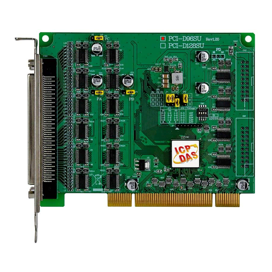
PCI-D96SU/D128SU Card Packing List The shipping package includes the following items: One PCI-D96SU or D128SU card as follows: PCI-D96SU PCI-D128SU One printed Quick Start Guide Note: If any of these items is missing or damaged, contact the dealer from whom you purchased the product. Save the shipping materials and carton in case you need to ship or store the product in the future. -
Page 4: Introduction
PCI-D96SU/D128SU Card 1. Introduction The PCI-D96SU/D128SU card is a new generation product provided by ICP DAS to meet RoHS compliance requirements. The PCI-D96SU/D128SU supports 3.3 V/5 V PCI bus. These cards provide 96/128 Digital I/O lines that consist of three/four 32-bit bi-directional ports for use in a variety of Digital I/O applications. - Page 5 PCI-D96SU/D128SU Card 1.2 Specifications Model Name PCI-D96SU PCI-D128SU Programmable Digital I/O Channels Digital Input Digital Signal Voltage Levels +1.8 V, +2.5 V, +3.3 V, +5 V +1.8 V Logic 0: < 0.65 V, Logic 1: > 1.2 V. +2.5 V Logic 0: <...
-
Page 6: Lock Diagram
PCI-D96SU/D128SU Card 1.3 Block Diagram Figure 1-3: Block Diagram of PCI-D96SU/D128SU User Manual, Ver. 1.0, Apr. 2019, PMH-031-10 Page 5... -
Page 7: Hardware Configuration
PCI-D96SU/D128SU Card 2. Hardware Configuration 2.1 Board Layout 1 2 3 4 CON1 Connector Refer to Section 2.2 “I/O Port Location” for more CN2 Connector (for PCI-D128SU only) details. CN1 Connector (for PCI-D128SU only) ... - Page 8 2.2 I/O Port Location There are three 32-bit I/O ports in the PCI-D96SU card, while there are four 32-bit I/O ports in the PCI-D128SU card. Each I/O port can be programmed as a DI or DO port. When the PC is first powered-on or reset all the ports are configured as DI ports.
- Page 9 PCI-D96SU/D128SU Card 2.3 Pull-high/Low Jumper Before installing the card into your computer, configure the DI Pull-high/low according to your requirements. Jumpers JP3 to JP6 are used to specify whether the Digital Input is either Pull-high or Pull-low. The following illustrates the jumper positions used to select the DI Pull-high/low: ...
- Page 10 PCI-D96SU/D128SU Card 2.4 DIO Operating Voltage Jumper Before installing the card into your computer, configure the DIO operating voltage according to your requirements. Jumpers JP1 and JP2 are used to specify the DIO operating voltage levels. The following illustrates the jumper positions used to select the digital signal voltage levels:...
- Page 11 Before installing the card into your computer, configure the Card ID according to your requirements. The PCI-D96SU/D128SU card has a Card ID switch (SW1) with which users can recognize the board by the ID via software when using two or more PCI-D96SU/D128SU cards in one computer. The default Card ID is 0x0.
- Page 12 PCI-D96SU/D128SU Card 2.6 Pin Assignments CN1/CN2: 20-pin flat-cable Connector for PCI-D128SU only (PD Port). CON1: 100-pin SCSI II Connector (PA, PB and PC Ports). User Manual, Ver. 1.0, Apr. 2019, PMH-031-10 Page 11...
- Page 13 PCI-D96SU/D128SU Card 2.7 Pattern Match Function The PCI-D96SU supports the pattern match function for Port0 (PA), Port1 (PB) and Port2 (PC) of Digital Input, while the PCI-D128SU supports the pattern match function for Port0 (PA), Port1 (PB), Port2 (PC) and Port3 (PD) of Digital Input. It monitors the status of the enabled input channels, which are chosen in Bar0+0x030, and compares the received state values with the compare values written in Bar0+0x020/0x24/0x28/0x2C.
-
Page 14: Igital Attern Unction
PCI-D96SU/D128SU Card 2.9 Digital Pattern Function The PCI-D96SU/D128SU supports the digital pattern function for Port2 (PC) of Digital Output. When the PC port is set to output mode and enabled pattern output, which is chosen in Bar0+0x05C. The digital pattern can be continuously generated on a PC port using a user-defined pattern data (Refer... -
Page 15: Hardware Installation
Chapter 4 “Software Installation”. Step 2: Configure the Card ID using the DIP Switch (SW1) on PCI-D96SU/D128SU. For detailed information about the card ID (SW1), please refer to Section 2.5 “Card ID Switch”. User Manual, Ver. 1.0, Apr. 2019, PMH-031-10 Page 14... - Page 16 PCI-D96SU/D128SU Card Step 3: Shut down and switch off the power to the computer, and then disconnect the power supply. Step 4: Remove the cover from the computer. Step 5: Select a vacant PCI slot. User Manual, Ver. 1.0, Apr. 2019, PMH-031-10 Page 15...
- Page 17 PCI-D96SU/D128SU Card Step 6: Unscrew and remove the PCI slot cover from the computer case. Step 7: Remove the connector cover from your board. Step 8: Carefully insert your board into the PCI slot by gently pushing down on both sides of the board until it slides into the PCI connector.
- Page 18 PCI-D96SU/D128SU Card Step 9: Confirm that the board is correctly inserted in the motherboard, and then secure your board in place using the retaining screw that was removed in Step 6. Step 10: Replace the covers on the computer. Step 11: Re-attach any cables, insert the power cord and then switch on the power to the computer.
-
Page 19: Software Installation
4.1 Obtaining/Installing the Driver Installer Package The driver installation package for PCI-D96SU/D128SU card can be found the ICP DAS FTP web site. Install the appropriate driver for your operating system. The location and website addresses for the installation package are indicated below. -
Page 20: Nstallation
PCI-D96SU/D128SU Card Step 2: When the “Welcome to the ICP DAS UniDAQ Driver Setup Wizard” screen is displayed, click the “Next>” button to start the installation. Step 3: On the “Information” screen, verify that the DAQ board is included in the list of supported devices, then click the “Next>”... - Page 21 Step 1: Correctly shut down and power off your computer and disconnect the power supply, and then install your board into the computer. For detailed information about the hardware installation of PCI-D96SU/D128SU card, refer to Chapter 3 “Hardware Installation”. Step 2: Power on the computer and complete the Plug and Play installation.
- Page 22 PCI-D96SU/D128SU Card Step 4: Click the “Finish” button. Step 5: Windows pops up “Found New Hardware” dialog box again. User Manual, Ver. 1.0, Apr. 2019, PMH-031-10 Page 21...
-
Page 23: Accessing Windows Device Manager
PCI-D96SU/D128SU Card 4.3 Verifying the Installation To verify that the driver was correctly installed, use the Windows Device Manager to view and update the device drivers installed on the computer, and to ensure that the hardware is operating correctly. The following is a description of how access the Device Manager in each of the major versions of Windows. - Page 24 PCI-D96SU/D128SU Card Windows Server 2003 Step 1: “Start” button and point to “Administrative Tools”, and then click the “Computer Click the Management” option. Step 2: “System Tools” item in the console tree, and then click “Device Manager”. Expand the ...
- Page 25 PCI-D96SU/D128SU Card Windows 8 Step 1: To display the Start screen icon from the desktop view, hover the mouse cursor over the bottom-left corner of screen. Step 2: Right-click the Start screen icon and then click “Device Manager”. Alternatively, press [Windows Key] +[X] to open the Start Menu, and then select Device Manager from the options list.
-
Page 26: Check That The Installation
PCI-D96SU/D128SU Card 4.3.2 Check that the Installation Check that the PCI-D96SU/D128SU card is correctly listed in the Device Manager window, as illustrated below. User Manual, Ver. 1.0, Apr. 2019, PMH-031-10 Page 25... -
Page 27: Board Testing
A CA-SCSI100-15 Cable (Optional, Website: http://www.icpdas.com/products/Accessories/cable/cable_selection.htm) A DN-100 Terminal Board (Optional, Website: http://www.icpdas.com/root/product/solutions/pc_based_io_board/daughter_boards/dn-100.html) Step 1: Connect the DN-100 terminal board to the CON1 connector on PCI-D96SU/D128SU card using the CA-SCSI100-15 cable. User Manual, Ver. 1.0, Apr. 2019, PMH-031-10 Page 26... - Page 28 PCI-D96SU/D128SU Card Step 2: Connect the Port0 (PA00~PA07) with Port1 (PB00~PB07). FG 51 52 53 54 55 56 57 58 59 60 61 62 63 64 65 66 67 68 69 70 71 72 73 74 75 NG 20 21 22 23 24 25 NG...
- Page 29 PCI-D96SU/D128SU Card Step 2: Confirm that your board has been successfully installed in the Host system. Note that the device number starts from 0. Step 3: Click the “TEST” button to start the test. Step 4: Check the results of the Digital Input and Digital Output functions test.
- Page 30 PCI-D96SU/D128SU Card 4. Click the “Digital Input” tab. 5. Select “Port 1” from the “Port Number” drop-down menu. 6. The DI indicators will turn red when the corresponding DO channels 0, 2, 4 and 6 are ON. ...
-
Page 31: I/O Register Addresses
6. I/O Register Addresses The PCI-D96SU/D128SU cards are I/O mapped devices that are easily configured from any language. The following is a summary of the address registry that can be used with the PCI-D96SU/D128SU. 6.1 Hardware ID During the power-on stage, the Plug and Play BIOS will assign an appropriate I/O address to each PCI-D96SU/D128SU card installed in the system. - Page 32 PCI-D96SU/D128SU Card Table 6-3: Address Mapping Register Function Description Offset Bar No. (HEX) Read Write 0x000 PA In/Out direction PA In/Out direction 0x004 PA In/Out Status read back PA In/Out Status read back 0x008 PB In/Out direction PB In/Out direction...
-
Page 33: Bar 0
These registers provide the function for configuration Digital Input or Output Port of the PCI-D96SU/D128SU card. Every ports uses 8-bit as a group that can be programmed to be a DI or a Note that all ports are used as DI ports when the PC is first turned on. -
Page 34: Compare Value Setting Register
PCI-D96SU/D128SU Card 6.3.3 Compare Value Setting Register (Read/Write): 0x020/0x024/0x028/0x02C PA/PB/PC/PD Port Compare Value Setting Function Port Type Read Write Compare Read back the current port’s Set the compare value and 0:31 Value compare value Clear port’s Interrupt status 6.3.4 Pattern Match/Change Status Control Register... - Page 35 PCI-D96SU/D128SU Card Function Port Type Read Write Read the PB Port’s Pattern Match PB_C_F active status. 1: Active, 0: Non Active Read the PC Port’s Pattern Match PC_C_F active status. 1: Active, 0: Non Active Read the PD Port’s Pattern Match PD_C_F active status.
-
Page 36: Clear Change Of Status Register
PCI-D96SU/D128SU Card 6.3.5 Clear Change of Status Register (Read/Write): 0x034/0x03C PA/PB Port Clear Change of Status Function Port Type Read Write Clear Clear Change of Status 1:31 Reserved 6.3.6 Pattern Clock Register (Read/Write): 0x054 PC Port’s Pattern CLK Function Port Type... -
Page 37: Start Pattern Output Register
PCI-D96SU/D128SU Card 6.3.8 Start Pattern Output Register (Read/Write): 0x05C Start PC Port’s Pattern Output Function Port Type Read Write Settings start/stop the Digital Pattern of PC Port. Read back the start/stop status of PC_START 1: Start Pattern Output, PC Port’s Digital Pattern... -
Page 38: Windows Api Function
PCI-D96SU/D128SU Card 7. Windows API Function For more details regarding the Windows API Functions for the PCI-D96SU/D128SU card, refer to UniDAQ SDK User manual, which can be downloaded from: http://ftp.icpdas.com/pub/cd/iocard/pci/napdos/pci/unidaq/manual/ 8. Daughter Boards DN-100 The DN-100 is a general-purpose DIN-Rail mountable daughter board containing female 100 pin D-sub I/O Connectors and is designed to allow easy field wiring connections. -
Page 39: Db-24Por
PCI-D96SU/D128SU Card DN-20/DN-20-381 The DN-20/20-381 is a general-purpose DIN-Rail mountable daughter board containing 20-pin header I/O Connectors and is designed to allow easy field wiring connections. Pins 01 to 20 on the DN-20 daughter board are connected to the CN1/CN2 connector on the PCI-D128SU using a 20-pin flat cable. - Page 40 PCI-D96SU/D128SU Card DB-24C The DB-24C has 24 channels of optically isolated digital outputs, arranged into four isolated banks. Each digital output offers a Darlington transistor and integral suppression diode for inductive load. The board interface to field logic signals, eliminating ground-loop problems and isolating the host computer from damaging voltages.
Need help?
Do you have a question about the PCI-D96SU and is the answer not in the manual?
Questions and answers