Table of Contents
Advertisement
Quick Links
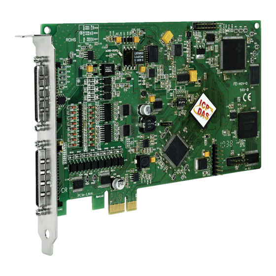
PCIe-LM4 User Manual
24-Bit Precision Load Cell Input Board
S
UPPORT
This manual relates to the following boards: PCIe-LM4.
W
ARRANTY
All products manufactured by ICP DAS are warranted against defective materials
for a period of one year from the date of delivery to the original purchaser.
W
ARNING
ICP DAS assumes no liability for damages consequent to the use of this product.
ICP DAS reserves the right to change this manual at any time without notice. The
information furnished by ICP DAS is believed to be accurate and reliable. However,
no responsibility is assumed by ICP DAS for its use, nor for any infringements of
patents or other rights of third parties resulting from its use.
C
OPYRIGHT
Copyright © 2020 by ICP DAS. All rights are reserved.
T
RADEMARKS
Names are used for identification purposes only and may be registered
trademarks of their respective companies.
C
US
ONTACT
If you have any questions, feel to contact us by email at:
service@icpdas.com or service.icpdas@gmail.com
We will respond to you within 2 working days.
Version 1.0, Jan. 2020
Advertisement
Table of Contents

Related Manuals for ICP DAS USA PCIe-LM4


Summary of Contents for ICP DAS USA PCIe-LM4
- Page 1 24-Bit Precision Load Cell Input Board Version 1.0, Jan. 2020 UPPORT This manual relates to the following boards: PCIe-LM4. ARRANTY All products manufactured by ICP DAS are warranted against defective materials for a period of one year from the date of delivery to the original purchaser.
-
Page 2: Table Of Contents
Connecting Pulse Output Signals......................... 19 2.7.2 Connecting Encoder Input Signals ....................... 21 ..............................23 SSIGNMENTS 2.8.1 CON1/2 Connector of the PCIe-LM4 ......................23 2.8.2 I/O Connector Signal Descriptions ....................... 24 2.8.3 Power Source ............................... 25 HARDWARE INSTALLATION ..........................26 SOFTWARE INSTALLATION ..........................30 .................. - Page 3 ..............................38 NTRODUCTION ........................39 ALIBRATION ROCESS 5.2.1 PCIe-LM4 Calibration Step........................... 39 WINDOWS API FUNCTION ..........................51 APPENDIX A: DAUGHTER BOARDS ..........................52 DN-68A ................................... 52 APPENDIX B: REVISION HISTORY ..........................53 User Manual, Ver. 1.0, Jan 2020, PMH-032-10 Page 3...
-
Page 4: Packing List
High-speed Multifunction Boards Packing List The shipping package should contain the following items: One multifunction board: PCIe-LM4 One printed Quick Start Guide Note: If any of these items is missing or damaged, contact the dealer from whom you purchased the product. -
Page 5: Introduction
The PCIe-LM4 also adds a Card ID switch. Users can set Card ID on a board and recognize the board by the ID via software when using two or more PCIe-LM4 cards in one computer. -
Page 6: Features
High-speed Multifunction Boards 1.1 Features The following is an overview of the general features provided by the PCIe-LM4 board. Refer to Section 1.3 for more details. Interface • PCI Express x1 • Card ID switch • Software Calibration Analog Input •... -
Page 7: Specifications
High-speed Multifunction Boards 1.3 Specifications The following is an overview of the specifications for the various models in the PCIe-LM4 Series. Model PCIe-LM4 Load Cell Transducer Channels A/D Converter 24-bit, 67 µs conversion time Sampling Rate 15 kS/s Over voltage Protection... - Page 8 High-speed Multifunction Boards FIFO Size 512 Samples Digital Input Channels Isolation Voltage 2500 V Compatibility Sink or Source, Photo coupler isolated channel with common power or ground Input Voltage Logic 0: 0 ~1 V/Logic 1: 5~24 V Response Speed 4 kHz (Typical) Trigger Mode Software Data Transfer...
- Page 9 High-speed Multifunction Boards Power Consumption 1 A @ +5 V (Max.) Operating Temperature 0 ~ 60 °C Storage Temperature -20 ~ 70 °C Humidity 5 ~ 85% RH, Non-condensing User Manual, Ver. 1.0, Jan 2020, PMH-032-10 Page 9...
-
Page 10: Applications
High-speed Multifunction Boards 1.4 Applications • Signal Analysis • FFT and Frequency Analysis • Transient Analysis • Temperature Monitor • Vibration Analysis • Energy Management • Other Industrial and Laboratory Measurement and Control User Manual, Ver. 1.0, Jan 2020, PMH-032-10 Page 10... -
Page 11: Hardware Configuration
High-speed Multifunction Boards 2 Hardware Configuration 2.1 Board Layout The following is an overview of the board layout for each of the PCIe-LM4 Series cards. PCIe-LM4 CON1 The Connector for Analog input and Analog Output. Refer to Section 2.8 Pin... -
Page 12: Card Id Switch (Sw1)
High-speed Multifunction Boards 2.2 Card ID Switch (SW1) The PCIe-LM4 includes an onboard Card ID switch (SW1) that enables the board to be recognized via software if two or more PCIe-8620/8622 boards are installed in the same computer. The default Card ID is 0x0. -
Page 13: System Block Diagram
High-speed Multifunction Boards 2.3 System Block Diagram The following is the block diagram for the PCIe-LM4: User Manual, Ver. 1.0, Jan 2020, PMH-032-10 Page 13... -
Page 14: Analog Input
PCIe-LM4 board. Input rage affects the resolution of the PCIe-LM4 for an AI channel Resolution refer to the voltage of one ADC code. 24-bit ADC converts Analog Inputs into one of 16777216 codes – that is, one of 16777216 possible digital values. -
Page 15: Connecting Analog Input Signals
High-speed Multifunction Boards 2.4.2 Connecting Analog Input Signals The PCIe-LM4 Series board can be used to measure differential type Analog Input signals for floating signal source. AI CH 0 HI PCIe-LM4 Floating Signal Source AI CH 0 LO 100 kΩ ~ 10 MΩ... -
Page 16: Connecting Load Cell Inputs Signals
High-speed Multifunction Boards 2.4.4 Connecting Load cell inputs Signals The PCIe-LM4 Series board can be used to measure Load cell transducer Input signals for floating signal source in differential mode. EXC+ EXC+ SENSE+ EXC- EXC- SENSE- AIx+ AIx- Load cell... -
Page 17: Analog Output
The PCIe-LM4 board provides two DA output channels, AO0 and AO1, and the onboard -5 V (-10 V) reference signal on the PCIe-LM4 may be used to generate a DA output range of 0 V to +5 V (+10 V). -
Page 18: Digital Input/Output
High-speed Multifunction Boards 2.6 Digital Input/Output The DIO signals, DO<0..15> and DI<0..15> are referenced to DI.COM and EXT.GND. The figure shows DI<0..15> configured for Digital Input and DO<0..15> configured for Digital Output. Digital Input wiring diagram Digital Readback as 1 Readback as 0 Input/Counter +10 ~ +30 VDC... -
Page 19: Motion Control
High-speed Multifunction Boards 2.7 Motion Control 2.7.1 Connecting Pulse Output Signals Figure 3: Internal pulse output circuit • Differential type: User Manual, Ver. 1.0, Jan 2020, PMH-032-10 Page 19... - Page 20 High-speed Multifunction Boards Figure 4: Wiring for differential type pulse output • Open collector TTL output Figure 5: Open collector TTL output User Manual, Ver. 1.0, Jan 2020, PMH-032-10 Page 20...
-
Page 21: Connecting Encoder Input Signals
High-speed Multifunction Boards 2.7.2 Connecting Encoder Input Signals Figure 6: Encoder input signal circuit Differential type encoder connection Figure 7: Differential type encoder wiring Open collector type encoder wiring: User Manual, Ver. 1.0, Jan 2020, PMH-032-10 Page 21... - Page 22 High-speed Multifunction Boards Figure 8: Open collector type encoder wiring User Manual, Ver. 1.0, Jan 2020, PMH-032-10 Page 22...
-
Page 23: Pin Assignments
High-speed Multifunction Boards 2.8 Pin Assignments 2.8.1 CON1/2 Connector of the PCIe-LM4 User Manual, Ver. 1.0, Jan 2020, PMH-032-10 Page 23... -
Page 24: I/O Connector Signal Descriptions
Output sharing a common wiring between transducers will degrade gain accuracy. Up to four 120-ohm load-cells can be connected to one PCIe-LM4. Load-cells with larger impedance can also be used. Remote-sense analog inputs for transducer excitation sensing. Always connect SENSEn+ to EXCn+, SENSEn- to... -
Page 25: Power Source
Never connect the +5 V power terminals to analog or digital ground or to any other voltage source on PCIe-LM4 or any other device. Doing so can damage the device and the computer. ICP DAS is not liable for damage resulting from such a connection. -
Page 26: Hardware Installation
Windows XP, etc. Installing the driver first helps reduce the time required for installation and restarting the computer. To install the PCIe-LM4 Series cards, follow the procedure described below: Step 1: Install the driver for the PCIe-LM4 board on your computer. For detailed information about installing the driver, refer to Chapter 4 Software Installation. - Page 27 High-speed Multifunction Boards Step 3: Shut down and switch off the power to the computer, and then disconnect the power supply. Step 4: Remove the cover from the computer. Step 5: Select a vacant PCI Express slot. User Manual, Ver. 1.0, Jan 2020, PMH-032-10 Page 27...
- Page 28 Step 7: Remove the connector cover from the PCIe-LM4 board. Step 8: Carefully insert the PCIe-LM4 board into the PCI Express slot by gently pushing down on both sides of the card until it slides into the PCI connector.
- Page 29 High-speed Multifunction Boards Step 9: Confirm that the card is correctly inserted in the motherboard, and then secure the PCIe-LM4 board in place using the retaining screw that was removed in Step 6. Step 10: Replace the covers on the computer.
-
Page 30: Software Installation
Obtaining/Installing the Driver Installer Package The driver installation package for PCIe-LM4 Series board can be found on the companion CD-ROM, or can be obtained from the ICP DAS FTP web site. Install the appropriate driver for your operating system. The location and website addresses for the installation package are indicated below. - Page 31 Step 8: Once the installation has completed, click “No, I will restart my computer later”, and then click the “Finish” button. For more detailed information about how to install the driver, refer to “Section 2.2 Install PCIe-LM4 Driver DLL” of the Software Manual, which can be downloaded from: http://www.icpdas.com/en/download/index.php?model=PCIe-LM4...
-
Page 32: Plug And Play Driver Installation
Plug and Play Driver Installation Step 1: Correctly shut down and power off your computer and disconnect the power supply, and then install the PCIe-LM4 Series board into the computer. For detailed information about the hardware installation of the PCIe-LM4 Series board, refer to Chapter 3 Hardware Installation. - Page 33 High-speed Multifunction Boards Step 4: Click the “Finish” button. Step 5: Windows pops up “Found New Hardware” dialog box again. User Manual, Ver. 1.0, Jan 2020, PMH-032-10 Page 33...
-
Page 34: Verifying The Installation
High-speed Multifunction Boards Verifying the Installation To verify that the driver was correctly installed, use the Windows Device Manager to view and update the device drivers installed on the computer, and to ensure that the hardware is operating correctly. The following is a description of how access the Device Manager in each of the major versions of Windows. - Page 35 High-speed Multifunction Boards Windows Server 2003 Step 1: “Start” button and point to “Administrative Tools”, and then click the “Computer Click the Management” option. Step 2: “System Tools” item in the console tree, and then click “Device Manager”. Expand the ...
- Page 36 High-speed Multifunction Boards Windows 8 Step 1: To display the Start screen icon from the desktop view, hover the mouse cursor over the bottom-left corner of screen. Step 2: Right-click the Start screen icon and then click “Device Manager”. Alternatively, press [Windows Key] +[X] to open the Start Menu, and then select Device Manager from the options list.
-
Page 37: Check The Installation
High-speed Multifunction Boards 4.3.2 Check the Installation Check that the PCIe-LM4 Series board is correctly listed in the Device Manager, as illustrated below. Installation successful User Manual, Ver. 1.0, Jan 2020, PMH-032-10 Page 37... -
Page 38: Calibration
5 Calibration Introduction When shipped from the factory, the PCIe-LM4 Series board is already fully calibrated, including the calibration coefficients that are stored in the onboard EEPROM. For a more precise application of voltages in the field, the procedure described below provides a method that allows the board installed in a specific system to be calibrated so that the correct voltages can be achieved for the field connection. -
Page 39: Step-By-Step Calibration Process
Calibration Program for the PCIe-LM4, which can be downloaded form: http://www.icpdas.com/en/download/index.php?model=PCIe-LM4 5.2.1 PCIe-LM4 Calibration Step Step 1: Select calibration board (1) Select “0 PCIe-LM4” from the “Select Calibration Board” drop-down menu. (2) Click the “RELOAD” button. User Manual, Ver. 1.0, Jan 2020, PMH-032-10 Page 39... - Page 40 Step 2: Calibrate the Analog Output Channel 0 (1) Connect the meter to measure the voltage from channel 0 (2) Connect meter(+) to PCIe-LM4.CON1.VO0 (Pin10) (3) Connect meter(-) to PCIe-LM4.CON1.AGND (Pin11) User Manual, Ver. 1.0, Jan 2020, PMH-032-10 Page 40...
- Page 41 High-speed Multifunction Boards Step 3: Calibrate the Unipolar 5 V, Unipolar 10 V, Bipolar 5 V and Bipolar 10 V for Analog Output Channel 0 (1) Use button “+” or “-” and adjust output voltage to voltage 5 V. (2) Use button “+” or “-” and adjust output voltage to voltage 0 V. (3) Use button “+”...
- Page 42 Step 4: Calibrate the Analog Output Channel 1 (1) Connect the meter to measure the voltage from channel 1 (2) Connect meter(+) to PCIe-LM4.CON1.VO1 (Pin12) (3) Connect meter(-) to PCIe-LM4.CON1.AGND (Pin13) User Manual, Ver. 1.0, Jan 2020, PMH-032-10 Page 42...
- Page 43 High-speed Multifunction Boards Step 5: Calibrate the Unipolar 5 V, Unipolar 10 V, Bipolar 5 V and Bipolar 10 V for Analog Output Channel 1 (1) Use button “+” or “-” and adjust output voltage to voltage 5 V. (2) Use button “+” or “-” and adjust output voltage to voltage 0 V. (3) Use button “+”...
- Page 44 High-speed Multifunction Boards Step 6: Calibrate the Analog Input Channel 4 to 9.9V (1) Connect 9.9 V voltage source to PCIe-LM4.CON1.AI4+ (Pin14) (2) Connect GND source to PCIe-LM4.CON1.A14- (Pin48) (3) Click CH4 Rate Group 0 “Read” button to get hexadecimal value (4) Click CH4 Rate Group 1 “Read”...
- Page 45 High-speed Multifunction Boards Step 7: Calibrate the Analog Input Channel 4 to 0V (1) Connect 0 V voltage source to PCIe-LM4.CON1.AI4+ (Pin14) (2) Connect GND source to PCIe-LM4.CON1.AI4- (Pin48) (3) Click CH4 Rate Group 0 “Read” button to get hexadecimal value (4) Click CH4 Rate Group 1 “Read”...
- Page 46 High-speed Multifunction Boards Step 8: Calibrate the Analog Input Channel 4 to 4.9V (1) Connect 4.9 V voltage source to PCIe-LM4.CON1.AI4+ (Pin14) (2) Connect GND source to PCIe-LM4.CON1.AI4- (Pin48) (3) Click CH4 Rate Group 0 “Read” button to get hexadecimal value.
- Page 47 High-speed Multifunction Boards Step 9: Calibrate the Analog Input Channel 4 to 2.49V (1) Connect 2.49 V voltage source to PCIe-LM4.CON1.AI4+ (Pin14) (2) Connect GND source to PCIe-LM4.CON1.AI4- (Pin48) (3) Click CH4 Rate Group 0 “Read” button to get hexadecimal value (4) Click CH4 Rate Group 1 “Read”...
- Page 48 High-speed Multifunction Boards Step 10: Calibrate the Analog Input Channel 4 to 1.24V (1) Connect 1.24 V voltage source to PCIe-LM4.CON1.AI4+ (Pin14) (2) Connect GND source to PCIe-LM4.CON1.AI4- (Pin48) (3) Click CH4 Rate Group 0 “Read” button to get hexadecimal value (4) Click CH4 Rate Group 1 “Read”...
- Page 49 High-speed Multifunction Boards Step 11: Calibrate the Analog Input Channel 0(Load Cell) to 200 mV (1) Connect 200 mV Loadcell source to PCIe-LM4.Analog input channel 0(Load Cell), Note: About signal connection , please refer to Sec. 2.2.4 (2) Click CH0 Rate Group 0“Read” button to get hexadecimal value (3) Click CH0 Rate Group 1“Read”...
- Page 50 High-speed Multifunction Boards Step 12: Calibrate the Analog Input Channel 0(Load Cell) to 200 mV (1) Connect 0 mV Loadcell source to PCIe-LM4.Analog input channel 0(Load Cell), Note: About signal connection , please refer to Sec. 2.2.4 (2) Click CH0 Rate Group 0“Read” button to get hexadecimal value (3) Click CH0 Rate Group 1“Read”...
-
Page 51: Windows Api Function
High-speed Multifunction Boards 6 Windows API Function For more details regarding the Windows API Functions for the PCIe-LM4 Series board, refer to UniDAQ SDK User manual, which can be downloaded from: http://www.icpdas.com/en/download/index.php?model=PCIe-LM4 User Manual, Ver. 1.0, Jan 2020, PMH-032-10 Page 51... -
Page 52: Appendix A: Daughter Boards
PCIe-LM4 Pins 01 to 68 on the DN-68A daughter board are connected to the CON1 connector on the PCIe-LM4 using a 68-pin male-male cable. The FG on the DN-68A is connected to the shielding wire of the 68-pin cable. User Manual, Ver. 1.0, Jan 2020, PMH-032-10 Page 52... -
Page 53: Appendix B: Revision History
High-speed Multifunction Boards Appendix B: Revision history This chapter provides revision history information to this document. The table below shows the revision history. Revision Date Description 2020.01.08 Initial issue User Manual, Ver. 1.0, Jan 2020, PMH-032-10 Page 53...
Need help?
Do you have a question about the PCIe-LM4 and is the answer not in the manual?
Questions and answers