Table of Contents
Advertisement
Quick Links
GDP-NI...
118
106
18
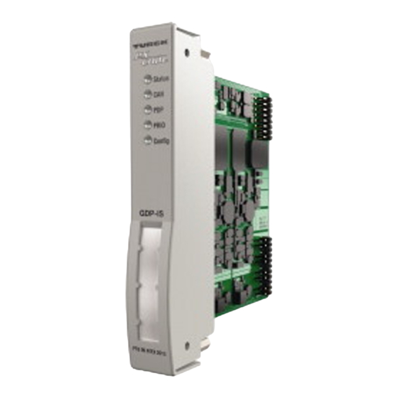
Wiring Diagram
Status
1 n.c.
GN/RD
2 n.c.
CAN
3 RxD / TxD-P
YE/RD
4 n.c.
internal
P
bus
PDP
5 DGND
R
YE/RD
6 DP
O
PRIO
F
7 n.c.
YE
I
8 RxD / TxD-N
B
Con g
9 n.c.
U
RD
S
internal
power
supply
DE
Kurzbetriebsanleitung
Gateway GDP-NI...
Weitere Unterlagen
Funktionen und Betriebsarten
Ergänzend zu diesem Dokument finden Sie im Inter-
Das Gateway verbindet die eigensicheren excom-
www.turck.com
net unter
folgende Unterlagen:
Module mit dem übergeordneten PROFIBUS-DP-
■
Datenblatt
Feldbussystem. Das Gateway wickelt den gesamten
■
Handbuch excom – Remote I/O für eigensichere
Prozessdatenverkehr ab und generiert Diagnose-
Stromkreise
Informationen für das übergeordnete Steuerungs-
■
Zulassungen
system. Zusätzlich übermittelt das Gerät hersteller-
■
EU-Konformitätserklärung (aktuelle Version)
spezifische Fehlercodes.
Zu Ihrer Sicherheit
Montieren
Bestimmungsgemäße Verwendung
GEFAHR
Das Gerät ist ausschließlich zum Einsatz im industriel-
Explosionsfähige Atmosphäre
len Bereich bestimmt.
Explosion durch zündfähige Funken oder heiße
Das Gateway GDP-NI... darf nur innerhalb des I/O-
Oberflächen der angeschlossenen Geräte
Systems mit den Modulträgern MT...-3G (PTB 00 ATEX
Gerät in Zone 2 nicht unter Spannung stecken
➤
2194 U bzw. IECEx PTB 13.0040 U) betrieben werden.
oder ziehen.
Das Gerät ist für den Einsatz im Nicht-Ex-Bereich und
in Zone 2 geeignet.
Mehrere Geräte können unmittelbar nebeneinander
Das Gateway bildet die Schnittstelle zwischen dem
in einen Modulträger MT...-3G montiert werden.
I/O-System excom und dem übergeordneten PRO-
Montageort gegen Wärmestrahlung, schnelle Tem-
➤
FIBUS-DP-Feldbussystem. Das Gerät kann mit einer
peraturschwankungen, Staub, Schmutz, Feuchtig-
max. Übertragungsgeschwindigkeit von 1500 kBaud
keit und andere Umwelteinflüsse schützen.
betrieben werden. Das Gerät unterstützt Linienredun-
Gerät in die dafür vorgesehene Position auf dem
➤
danz und Systemredundanz.
Modulträger stecken und deutlich spürbar einras-
Jede andere Verwendung gilt als nicht bestimmungs-
ten lassen.
gemäß. Für daraus resultierende Schäden übernimmt
Turck keine Haftung.
Anschließen
GEFAHR
Allgemeine Sicherheitshinweise
■
Explosionsfähige Atmosphäre
Nur fachlich geschultes Personal darf das Gerät
Explosion durch zündfähige Funken
montieren, installieren, betreiben, einstellen und
SUB-D-Steckverbinder auf dem Modulträger
➤
instand halten.
in Zone 2 nicht unter Spannung stecken oder
■
Das Gerät erfüllt ausschließlich die EMV-Anforde-
ziehen.
rungen für den industriellen Bereich und ist nicht
zum Einsatz in Wohngebieten geeignet.
Durch Aufstecken auf den Modulträger ist das Gerät
■
Nur Geräte miteinander kombinieren, die durch
mit der internen Energieversorgung und Daten-
ihre technischen Daten für den gemeinsamen
kommunikation des Modulträgers verbunden. Zum
Einsatz geeignet sind.
Anschluss an den Feldbus steht ein Standard-SUB-D-
Bei Einsatz im sicheren Bereich:
Steckverbinder auf dem Modulträger zur Verfügung.
■
Wird Verschmutzungsgrad 2 nicht eingehalten,
In Betrieb nehmen
Gerät in ein Schutzgehäuse mind. IP54 einbauen.
Nach Anschluss der Leitungen und Aufschalten der
Hinweise zum Ex-Schutz
Versorgungsspannung geht das Gerät automatisch in
■
Bei Einsatz des Gerätes in Ex-Kreisen muss der
Betrieb.
Anwender über Kenntnisse im Explosionsschutz
Betreiben
(EN 60079-14 etc.) verfügen.
■
Nationale und internationale Vorschriften für den
LED-Funktionen
Explosionsschutz beachten.
LED
■
Gerät nur innerhalb der zulässigen Betriebs- und
Status
Umgebungsbedingungen (siehe Technische Daten
und Vorgaben durch die Ex-Zulassung) einsetzen.
CAN
Auflagen durch die ATEX- und IECEx-Zulassung
■
Bei einer netzgebundenen Einspeisung des RS485-
Feldbusses eine Sicherheitskleinspannung (SELV)
oder Funktionskleinspannung (PELV) gemäß den
PDP
mechanischen Anforderungen der EN 60364-4-41
verwenden.
■
Gerät mit dem Modulträger MT...-3G in ein separat
zugelassenes Gehäuse nach EN IEC 60079-0 mit ei-
ner Schutzart mind. IP54 nach EN 60529 montieren.
Produktbeschreibung
PRIO
(Redundanz-
Geräteübersicht
status)
Siehe Abb. 1: Abmessungen
Config
CAN leuchtet rot und
Config blinkt rot
EN
Quick Start Guide
Gateway GDP-NI...
Other documents
Besides this document, the following material can be
found on the Internet at www.turck.com:
■
Data sheet
■
excom manual — Remote I/O for intrinsically safe
circuits
■
Approvals
■
Eu Declaration Of Conformity (current version)
For your safety
Intended use
The device is designed only for use in industrial areas.
The gateway GDP-NI... may only be operated within
I/O systems in conjunction with MT...-3G (PTB 00
ATEX 2194 U or IECEx PTB 13.0040 U) module racks.
The device is suitable for use in non-Ex areas and in
Zone 2.
The gateway forms the interface between the excom
I/O system and the higher-level PROFIBUS DP fieldbus
system. The device can be operated at a maximum
transfer rate of 1500 kBaud. The device supports line
redundancy and system redundancy.
Any other use is not in accordance with the intended
use. Turck accepts no liability for any resulting dam-
age.
General safety notes
■
The device must only be mounted, installed, oper-
ated, configured and maintained by trained and
qualified personnel.
■
The device fulfills exclusively the EMC requirements
for industrial applications and is not suitable for use
in residential areas.
■
Only combine devices if their technical data renders
them suitable to be used in a combined manner.
When used in the non-Ex area:
■
If contamination level 2 is not maintained, install
the device in a protective enclosure of at least IP54.
Notes on explosion protection
■
When using the device in Ex circuits, the user must
also have knowledge of explosion protection
(EN 60079-14 etc.).
■
Observe national and international regulations for
explosion protection.
■
Only use the device within the permissible operat-
ing and ambient conditions (see technical data and
Ex approval specifications).
Farbe
Bedeutung
grün
betriebsbereit
Requirements from the ATEX and IECEx approval
aus
keine Versorgung
■
If power is supplied to the RS485 fieldbus from the
gelb
interne Kommunikation in
grid, use a safety extra-low voltage (SELV) or func-
Ordnung
tional extra-low voltage (PELV) in accordance with
rot
keine Kommunikation
the mechanical requirements of EN 60364-4-41.
über den Rückwandbus
■
Mount the device with the module rack MT...-3G
möglich
in a separately approved enclosure in accordance
blinkt gelb ungültige PROFIBUS-DP-
with EN IEC 60079-0 with a degree of protection of
Adresse (000)
at least IP54 as per EN 60529.
rot
kein Datenaustausch mit
PROFIBUS-DP-Master
Product description
gelb
Datenaustausch mit
Device overview
PROFIBUS-DP-Master
See Fig. 1: Dimensions
aus
Gateway passiv
gelb
Gateway aktiv
aus
Konfiguration in Ordnung
blinkt rot
Konfigurationsfehler
(fehlende oder falsch
gesteckte Module)
keine interne
Kommunikation
Functions and operating modes
The gateway connects the intrinsically safe excom
modules with the higher-level PROFIBUS DP fieldbus
system. The gateway handles all process data traffic
and generate diagnostic information for the higher-
level control system. In addition, the device transmits
manufacturer-specific error codes.
Installing
DANGER
Potentially explosive atmosphere
Explosion by ignition sparks or hot surfaces of the
connected devices
Do not connect or remove the device when ener-
➤
gized in Zone 2.
Multiple devices can be mounted directly next to each
other in an MT...-3G module rack.
Protect the mounting location from radiated heat,
➤
sudden temperature fluctuations, dust, dirt, humid-
ity and other ambient influences.
Fit the device at the position intended for it on the
➤
module rack and snap it fully into position.
Connection
DANGER
Potentially explosive atmosphere
Risk of explosion due to ignitable sparks
Do not connect or disconnect the SUB-D con-
➤
nector on the module rack when energized in
Zone 2.
By plugging the device onto the module rack, it is
connected to the module rack's internal power supply
and data communication. A standard SUB-D connec-
tor is provided on the module rack for connection to
the fieldbus.
Commissioning
The device is operational automatically once the
cables are connected and the power supply is
switched on.
Operation
LED Functions
LED
Color
Meaning
Status
Green
Ready for operation
Off
No supply
CAN
Yellow
Internal communication
OK
Red
No communication pos-
sible via the backplane bus
PDP
Yellow
Invalid PROFIBUS-DP
flashing
address (000)
Red
No data exchange with
PROFIBUS DP master
Yellow
Data exchange with
PROFIBUS DP master
PRIO
Off
Gateway passive
(Redundan-
Yellow
Gateway active
cy status)
Config
Off
Configuration OK
Flashing
Configuration error (miss-
red
ing or incorrectly inserted
modules)
CAN lights up red and
No internal
Config flashes red
communication
© Hans Turck GmbH & Co. KG | D301285 2021-01 V2.1
Advertisement
Table of Contents

Related Manuals for turck GDP-NI Series


Summary of Contents for turck GDP-NI Series
- Page 1 Konfigurationsfehler CAN lights up red and No internal (fehlende oder falsch Config flashes red communication gesteckte Module) CAN leuchtet rot und keine interne Config blinkt rot Kommunikation © Hans Turck GmbH & Co. KG | D301285 2021-01 V2.1...
- Page 2 Acc. to Namur NE21 Hans Turck GmbH & Co. KG | Witzlebenstraße 7, 45472 Mülheim an der Ruhr, Germany | Tel. +49 208 4952-0 | Fax +49 208 4952-264 | more@turck.com | www.turck.com © Hans Turck GmbH & Co. KG | D301285 2021-01 V2.1...
- Page 3 Config pisca em interna Aperçu de l’appareil La LED CAN est rouge et pas de communication vermelho Voir Fig. 1 : Dimensions la LED Config clignote interne rouge © Hans Turck GmbH & Co. KG | D301285 2021-01 V2.1...
- Page 4 Acc. to Namur NE21 Hans Turck GmbH & Co. KG | Witzlebenstraße 7, 45472 Mülheim an der Ruhr, Germany | Tel. +49 208 4952-0 | Fax +49 208 4952-264 | more@turck.com | www.turck.com © Hans Turck GmbH & Co. KG | D301285 2021-01 V2.1...
- Page 5 황색 게이트웨이 활성 장치 개요 태) 참조 그림 1: 치수 Config 꺼짐 구성 정상 적색 점멸 구성 오류(모듈이 없거나 잘못 삽입됨) CAN 표시등이 적색으 내부 로 켜지고 Config가 적 통신 없음 색 점멸 © Hans Turck GmbH & Co. KG | D301285 2021-01 V2.1...
- Page 6 Acc. to Namur NE21 Hans Turck GmbH & Co. KG | Witzlebenstraße 7, 45472 Mülheim an der Ruhr, Germany | Tel. +49 208 4952-0 | Fax +49 208 4952-264 | more@turck.com | www.turck.com © Hans Turck GmbH & Co. KG | D301285 2021-01 V2.1...
Need help?
Do you have a question about the GDP-NI Series and is the answer not in the manual?
Questions and answers