Table of Contents
Advertisement
Quick Links
Advertisement
Chapters
Table of Contents

Related Manuals for turck BL67-PG-EN-IP


Summary of Contents for turck BL67-PG-EN-IP
- Page 1 BL67 – programmable Gateway BL67-PG-EN-IP USER MANUAL...
- Page 2 No part of this manual may be reproduced in any form (printed, photocopy, microfilm or any other process) or processed, dupli- cated or distributed by means of electronic systems without written permission of Hans Turck GmbH & Co. KG, Mülheim an der Ruhr. Subject to alterations without notice.
- Page 3 Before starting the installation Disconnect the power supply of the device. Ensure that devices cannot be accidentally restarted. Verify isolation from the supply. Earth and short circuit. Cover or enclose neighboring units that are live. Follow the engineering instructions (AWA) of the device concerned.
- Page 4 been installed with the housing closed. Desktop or portable units must only be operated and controlled in enclosed housings. Measures should be taken to ensure the proper restart of programs interrupted after a voltage dip or failure. This should not cause dangerous operating states even for a short time. If necessary, emergency-stop devices should be implemented.
-
Page 5: Table Of Contents
General......................3-2 Function ......................3-3 Programming................... 3-3 Technical Data ..................... 3-4 Gateway structure ................... 3-5 Connection possibilities ................3-10 Field bus connection ................3-10 Power supply via 7/8" connector ............3-11 Connection PS2 female connector ............3-12 D301044 1007 BL67-PG-EN-IP... - Page 6 Installation of the BL67 Target Support Packages ........5-3 Installation ....................5-4 BL67 Hardware Configuration ..............5-6 Configuration/ Programming of the PG in CoDeSys ........5-7 Creating a new project ................5-7 Configuration of the BL67 Station............... 5-13 Parameterization of the I/O modules............. 5-14 D301044 1007 BL67-PG-EN-IP...
- Page 7 Programming of the BL67-PG-xxx ............. 5-20 Online ....................5-21 Creating a boot project ................. 5-23 EtherNet/IP-Communication between PG and Superordinate PLC ... 5-24 Configuration of the BL67-PG-EN-IP in RSLogix........5-27 Guidelines for Station Planning Module Arrangement ..................6-2 Random module arrangement..............6-2 Complete Planning..................
- Page 8 Table of Contents Appendix Network Configuration .................. 8-2 Changing the IP address of a PC/network interface card....... 8-3 Deactivating/ adapting the firewall in Windows XP....... 8-10 Nominal Current Consumption of Modules at Ethernet ......8-13 Glossary Index D301044 1007 BL67-PG-EN-IP...
- Page 9 About this Manual Documentation Concept ..............2 General Information................3 Prescribed use ....................3 Notes concerning planning /installation of this product......3 Description of Symbols Used............. 4 List of Revisions ................5 D301044 1007 BL67-PG-EN-IP...
-
Page 10: About This Manual
BL67 I/O-modules (TURCK-Documentation-No.: German D300572/ English D300529) Furthermore, the manual mentioned above contains a short descrip- tion of the project planning and diagnostics software for TURCK I/O-systems, the engineering software I/O-ASSISTANT. D301044 1007 BL67-PG-EN-IP... -
Page 11: General Information
Please read this section carefully. Safety aspects cannot be left to chance when dealing with electrical equipment. This manual contains all necessary information about the prescibed use of the programmable TURCK gateway BL67-PG-EN-IP. It has been specially conceived for personnel with the necessary qualifications. -
Page 12: Description Of Symbols Used
This sign can be found next to all general notes that supply impor- tant information about one or more operating steps. These specific notes are intended to make operation easier and avoid unnecessary work due to incorrect operation. D301044 1007 BL67-PG-EN-IP... -
Page 13: List Of Revisions
In comparison to the previous manual edition, the following changes/ revisions have been made: Chapter Subject/ changed Table 1: List of revisions Description Chap. 5 Configuration of the BL67-PG-EN-IP in RSLogix, page 5-27. Note The publication of this manual renders all previous editions invalid. D301044 1007 BL67-PG-EN-IP... - Page 14 About this Manual D301044 1007 BL67-PG-EN-IP...
-
Page 15: Bl67 Philosophy
BL67 Philosophy The Basic Concept ................2 Flexibility......................2 Convenient handling..................3 BL67 Components ................4 Gateways.....................4 Electronic modules..................5 – Power feeding modules ................5 Base modules....................6 End plate ....................7 D301044 1007 BL67-PG-EN-IP... -
Page 16: The Basic Concept
All other BL67 modules are not dependent on the fieldbus used. Flexibility A BL67 station can contain modules in any combination, which means it is possible to adapt the system to practically all applica- tions in automated industries. D301044 1007 BL67-PG-EN-IP... -
Page 17: Convenient Handling
After disconnection of the load, the electronic modules can be plugged or pulled when the station is being commissioned or for maintenance purposes, without having to disconnect the field wiring from the base modules. D301044 1007 BL67-PG-EN-IP... -
Page 18: Bl67 Components
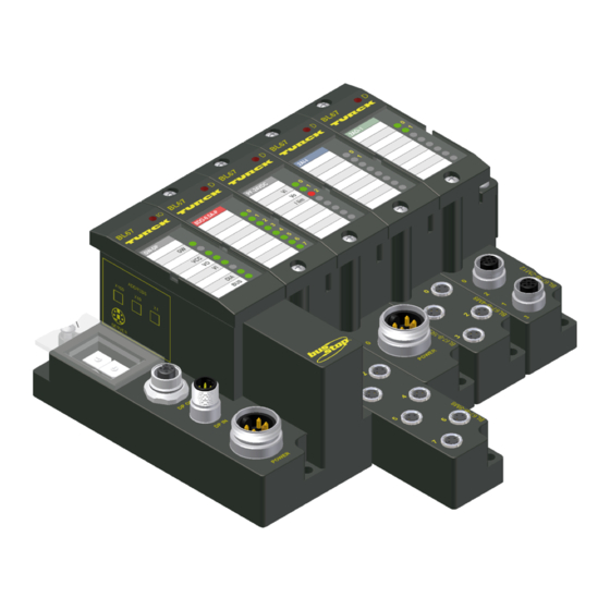
C base module Gateways The gateway connects the fieldbus to the I/O-modules. It is respon- sible for handling the entire process data and generates diagnostic information for the higher-level master and the software tool I/O-ASSISTANT. Figure 2: BL67 gateway D301044 1007 BL67-PG-EN-IP... -
Page 19: Electronic Modules
Note For detailed information about the individual BL67 I/O components, please refer to the chapters 2 to 8 of the manual "BL67- I/O-mod- ules" (TURCK Documentation-No.: German D300572; English: D300529). The "Appendix" to the manual mentioned above contains (amongst others) a list of all BL67 components and the assignment of elec- tronic modules to base modules. -
Page 20: Base Modules
1 x M12, 2 x M12, 2 x M12-P, 4 x M12, 4 x M12-P 4 x M8, 8 x M8 1 x M12-8 1 × M23, 1 x M23-19 1 x 7/8" (for Power Feeding Module) Figure 4: example of a base module D301044 1007 BL67-PG-EN-IP... -
Page 21: End Plate
End plate An end plate on the right-hand side physically completes the BL67 station. It protects the module bus connections of the last base module in a station and guarantees the protection class IP67. Figure 5: end plate D301044 1007 BL67-PG-EN-IP... - Page 22 BL67 Philosophy D301044 1007 BL67-PG-EN-IP...
-
Page 23: Ethernet/Ip
– IP (Internet Protocol) ................3 – TCP (Transmission Control Protocol) ............3 Network-topology..................4 – Transmission media .................4 Addressing on EtherNet/IP..............4 – Ethernet MAC-ID ..................4 – IP address ....................5 Network classes ..................6 Checking the communication via "ping-signals" ........7 ARP (Address Resolution Protocol).............8 D301044 1007 BL67-PG-EN-IP... -
Page 24: System Description
Common Industrial Protocol (CIP), the protocol that provides real-time I/O messaging and information/peer-to-peer messaging. ControlNet and DeviceNet networks also use CIP. Note For further infomation about CIP and EtherNet/IP, please contact also the user organization ODVA (www.odva.org). D301044 1007 BL67-PG-EN-IP... -
Page 25: Ip (Internet Protocol)
Application Object Library Application Layer Application Explicit, I/O, Routing Layer Encapsulation Transport DeviceNet ControlNet and Data Link Layer Transport Transport DeviceNet ControlNet Ethernet Physical physical physical physical Layer layer layer layer ATM, Firewire, USB, Blue Tooth Ethernet/IP D301044 1007 BL67-PG-EN-IP... -
Page 26: Network-Topology
IEEE (Institute of Electrical and Electronics Engineers, New York). The first 3 bytes of the MAC-ID contain a manufacturer identifier (Turck: 00:07:46:xx:xx:xx). The last 3 bytes can be chosen freely by the manufacturer for each device and contain a serial number. -
Page 27: Ip Address
The IP address is a 4-byte-value which contains the address of the network to which the node is connected as well as the host address in the network. The IP address of the BL67-PG-EN-IP gateway is predefined as follows: IP address: 192.168.1.×××... -
Page 28: Network Classes
1.×××.×××.×××- 126/ 2 126.×××.×××.××× 128.0.×××.××× - 191.255.×××.××× 192.0.0.××× - / 256 223.255.255.××× According to their predefined address 192.168.1.××× BL67 gate- ways are nodes on a Class C network. D301044 1007 BL67-PG-EN-IP... -
Page 29: Checking The Communication Via "Ping-Signals
For that purpose, enter the command "ping" and the IP address of the network node to be checked. If the node answers the ping-signal, it is ready for communication and takes part in the data transfer. Figure 8: ping-signal D301044 1007 BL67-PG-EN-IP... -
Page 30: Arp (Address Resolution Protocol)
Write a ping command for the respective station/ IP address: (example: "x:\\ping 192.168.1.100"). Via the command "x:\\arp -a", the MAC-ID (00-07-46-ff-60-13) for this IP address is determined. This MAC-ID clearly identifies the network node. Figure 9: Determination of the MAC-ID of a BL67 module via D301044 1007 BL67-PG-EN-IP... -
Page 31: Technical Features
Address setting via BootP-mode ..............18 Address setting via DHCP-mode ..............19 Address setting via PGM-mode ..............20 Addressing via PGM-DHCP ..............21 Address setting via the software "I/O-ASSISTANT" .........22 SET Button..................24 Status Indicators/Diagnostic Messages Gateway......25 Diagnostic messages via LEDs ..............25 D301044 1007 BL67-PG-EN-IP... -
Page 32: General
Technical Features General This chapter contains the general technical description of the programmable BL67 gateway for EtherNet/IP. D301044 1007 BL67-PG-EN-IP... -
Page 33: Function
The programmable BL67 gateways can be used as an autonomous PLC or as a de-central PLC in a network interconnection for fast signal processing Note The programmable BL67 gateway BL67-PG-EN-IP is designed as a Single Task System. The gateway is the connection between the BL67 I/O-modules and the Ethernet-network. -
Page 34: Technical Data
BL67-PG-EN-IP A power supply B Ethernet C n.c. D SET-button E service- interface F rotary coding switches G module bus LED H designation status LED J RUN/STOP LED K LEDs for supply voltage monitoring L Ethernet LEDs D301044 1007 BL67-PG-EN-IP... -
Page 35: Gateway Structure
Ethernet gateway the galvanically permissible range 18 to 30 VDC isolated module bus supply Field supply V 24 VDC permissible range 18 to 30 VDC 600 mA current consump- tion CPU + module bus at maximum system extension D301044 1007 BL67-PG-EN-IP... - Page 36 (IL, LD, FDB, SFC, ST) – Application tasks – No. of POUs (Program 1024 Organization Unit) – Programming interfaces RS232-interface, Ethernet Processor RISC, 32 bit – Cycle time < 1 ms for 100 IL-commands (without I/O-cycle) D301044 1007 BL67-PG-EN-IP...
- Page 37 Resistance to vibration according to EN 61131 – 10 to 57 Hz,constant amplitude 0.075 mm, 1 g – 57 to 150 Hz, constant acceleration 1 g – Vibration mode frequency cycles with a change rate of 1 octave/min D301044 1007 BL67-PG-EN-IP...
- Page 38 Air discharge (direct) 8 kV Relay discharge (indi- 4 kV rect) Electromagnetic HF fields according to IEC 61131-2 Fast transients (Burst) according to IEC 61131-2 Conducted interferences according to IEC 61000-4-6 induced by HF fields 10 V Criteria A D301044 1007 BL67-PG-EN-IP...
- Page 39 This device can cause radio disturbances in residential areas and in small industrial areas (residential, business and trading). In this case, the operator can be required to take appropriate measures to sup- press the disturbance at his own cost. D301044 1007 BL67-PG-EN-IP...
-
Page 40: Connection Possibilities
According to CIP-standards, the M12 female connector is designed as a 4-pole and D-coded connector. Figure 12: M12-female connector Table 3: Pin-No. Pin assignment Transmission Data + Receive Data + Transmission Data - Receive Data - 3-10 D301044 1007 BL67-PG-EN-IP... -
Page 41: Power Supply Via 7/8" Connector
Feed-in of nominal voltage for input modules (sensor supply); also used for the generation of the system supply voltage white ) Feed-in of nominal voltage for output modules (can be switched off sepa- rately) D301044 1007 BL67-PG-EN-IP 3-11... -
Page 42: Connection Ps2 Female Connector
The interface is conceived as a 6-pole mini DIN connector. In order to connect the gateway to the PC, two types of cables can be used: special I/O-ASSISTANT-connection cable from TURCK (IOASSISTANT-ADAPTERKABEL-BL20/BL67; Ident-no.: 6827133) Commercially available PS/2 cable with adapter cable... -
Page 43: Connection Using Commercially Available Cables
1 x PS/2 cable (PS/2 male connector/PS/2 male connector) (commercially available keyboard extension cable) 1 x adapter cable (PS/2 female connector/SUB-D female connector) (commercially available extension cable for a PC mouse) Figure 18: PS/2 female con- nector on the gateway (top view) D301044 1007 BL67-PG-EN-IP 3-13... - Page 44 BL67 gateway: Pin- Male connector male connector PS/2 female A not supported connector by all adapter cables. +5 V 4, 6 DTR, DSR (from gateway) DATA not connected – – n.c. (DATA2) +5 V /CtrlMode n.c. (CLK2) 3-14 D301044 1007 BL67-PG-EN-IP...
-
Page 45: Address Setting
Address Setting Address Setting The addressing of BL67-PG-EN-IP can be realized via different modes: rotary mode (manual addressing via rotary coding-switches) PGM mode (manual addressing via software) BootP mode, DHCP mode (automatic addressing via BootP/ DHCP-server at the boot-up of the gateway). -
Page 46: Default Settings Of The Gateway
10 000: 192.168.1.254 1 - 254: static rotary 300: BootP 400: DHCP 500: PGM 600: PGM-DHCP Attention After every change of the address-mode, a voltage reset must be carried out. 3-16 D301044 1007 BL67-PG-EN-IP... -
Page 47: Address Setting Via The Rotary-Mode
EEPROM. Thus, they will get lost in case of a subsequent address-assignment via a BootP/ DHCP or PGM. Attention After changing the position of the rotary coding-switches, a voltage reset must be carried out to store the new address. D301044 1007 BL67-PG-EN-IP 3-17... -
Page 48: Address Setting Via Bootp-Mode
BootP-server are stored in the gateway’s non-vola- tile memory. If the gateway is subsequently switched to rotary- or PGM-mode, the settings carried out via BootP (IP address, subnet mask, etc) will be taken from the module’s EEPROM. 3-18 D301044 1007 BL67-PG-EN-IP... -
Page 49: Address Setting Via Dhcp-Mode
In "manual allocation", a client's IP address is assigned by the network administrator, and DHCP is used simply to convey the assigned address to the client. D301044 1007 BL67-PG-EN-IP 3-19... -
Page 50: Address Setting Via Pgm-Mode
× 10 × 1 Note In the PGM-mode, all network settings (IP address, subnet mask, etc.) are read from the module’s internal EEPROM. The settings carried out in the rotary-mode are stored in the module’s non-volatile EEPROM. 3-20 D301044 1007 BL67-PG-EN-IP... -
Page 51: Addressing Via Pgm-Dhcp
Address Setting Addressing via PGM-DHCP The addressing of the BL67 EtherNet/IP gateway via PGM-DHCP is at the moment comparable to the addressing via DHCP (see page 3-19). D301044 1007 BL67-PG-EN-IP 3-21... -
Page 52: Address Setting Via The Software "I/O-Assistant
Figure 25: Interface Ethernet The IP address as well as the subnet mask of the TURCK Ethernet gateways can be changed according to the application by using the integrated Address Tool. Changes in the network-configuration are only accepted in the... - Page 53 Attention Please observe that, if the system integrated Windows-firewall is ac- tivated, difficulties may occur during the communication between the gateway and the Address-tool. The firewall may possibly inhibit the access of the tool on Ethernet. D301044 1007 BL67-PG-EN-IP 3-23...
-
Page 54: Set Button
Note Please press the SET button for 10 seconds after every change in the station’s hardware configuration in order to save the Current Configuration as the Reference Configuration in the Gateway. 3-24 D301044 1007 BL67-PG-EN-IP... -
Page 55: Status Indicators/Diagnostic Messages Gateway
1 LED for displaying if the gateway/ the program in the gateway has started: RUN/STOP 3 LEDs for monitoring the voltage supply (system, V / inputs, / outputs, V 2 LEDs for the Ethernet communication (fieldbus-LEDs): LINK/ ACT and MS. D301044 1007 BL67-PG-EN-IP 3-25... - Page 56 → – Dismount modules possible reasons: – Replace the gateway. – too many modules connected to the gateway – short circuit in connected module – hardware error in gateway 3-26 D301044 1007 BL67-PG-EN-IP...
- Page 57 → – Dismount modules possible reasons: – Replace the gateway. – too many modules connected to the gateway – short circuit in connected module – hardware error in – gateway D301044 1007 BL67-PG-EN-IP 3-27...
- Page 58 – Start the gateway/ the flashing gateway, PLC not yet PLC program. started or stopped. PLC test during – gateway start. CPU not supplied – Check the system supply at the gateway. Green Module bus and CPU running 3-28 D301044 1007 BL67-PG-EN-IP...
- Page 59 – Check the wiring of the flashing, system running voltage supply at the gateway Green, Overvoltage V flashing, system running 4 Hz Short circuit or over- – Automatic restart when load at sensor supply debugging. → sensor supply is switched off D301044 1007 BL67-PG-EN-IP 3-29...
- Page 60 Yellow Link, 10 Mbit/s Yellow, Ethernet Traffic 10 Mbit/s flashing Green Displays an active CIP Class 1 I/O connection Green, Gateway is ready for flashing operation Gateway indicates error Red, DHCP/BootP search flashing of settings 3-30 D301044 1007 BL67-PG-EN-IP...
-
Page 61: Implementation Of Ethernet/Ip
– Message Router Request/Response Formats ........12 Assembly Object ..................18 Connection Manager Object ..............20 Port Object ....................22 TCP/IP Interface Object ................24 Ethernet Link Object..................31 VSC-Vendor Specific Classes ............34 – Class Instances of the VSC ..............35 – Gateway Class (VSC 100) ..............36 D301044 1007 BL67-PG-EN-IP... -
Page 62: The Ethernet/Ip Communications Profile
Consists of a service field with the most significant bit set. This is an echo of the service code in the request message with the most significant bit set. A reserved byte follows the service code, which is followed by the General Status code. D301044 1007 BL67-PG-EN-IP... -
Page 63: Communications Profile Of The Bl67 Ethernet/Ip Gateway
It is not recommended for frequent messaging because the UCMM input queue in a product is typically limited to just a few messages. Once this limit is reached, subsequent requests are ignored and must be retried. D301044 1007 BL67-PG-EN-IP... -
Page 64: Connected Explcit Messaging
The purpose is to transfer data in the most effi- cient manner possible. The Connection ID is a number that is associated with a communi- cation relationship. Receiving nodes decode this key to know whether they must accept the data or not. D301044 1007 BL67-PG-EN-IP... -
Page 65: Classes And Instances Of The Ethernet/Ip-Gateway
The Connection Manager Class allocates (0×06) Manager and manages the internal resources associated with both I/O and Explicit Messaging Connections. The specific instance generated by the Connection Manager Class is referred to as a Connection Instance or a Connection Object. D301044 1007 BL67-PG-EN-IP... - Page 66 Port Object Provides a standard way of describing a (0×F4) device’s ports. TCP/IP Contains the device TCP/IP-related (0×F5) Interface configuration information. Object Ethernet Contains link-specific counters and (0×F6) Link Object status information for an Ethernet 802.3 communications interface. D301044 1007 BL67-PG-EN-IP...
-
Page 67: Identity Object
Ltd. and adapted to BL67. Class attributes Table 8: Attr. No. Attribute Name Get/ Type Value Class attributes 1 (0×01) REVISION UINT 2 (0×02) MAX OBJECT UINT INSTANCE 6 (0×06) MAX CLASS UINT ATTRIBUTE 7 (0×07) MAX INSTANCE UINT ATTRIBUTE D301044 1007 BL67-PG-EN-IP... - Page 68 USINT 0x02 DEVICE WORD See Table 10: „Device (0×05) STATUS Status” SERIAL UDINT Contains the ident-no. of the (0×06) NUMBER product (3 last bytes of the MAC-ID). PRODUCT STRUCT BL67-PG-EN-IP (0×07) NAME LENGTH USINT NAME STRING [13] D301044 1007 BL67-PG-EN-IP...
- Page 69 01 (0x01) Get_Attribute_All Returns a predefined listing of this objects attributes. 05 (0x05) Reset Starts the Reset service for the device. 14 (0x0E) Get_Attribute_Single Returns the contents of a specified attribute. 16 (0x10) Set_Attribute_Single Modifies a single attribute. D301044 1007 BL67-PG-EN-IP...
-
Page 70: Message Router Object
Attr. No. Attribute Name Get/ Type Value Class attributes 1 (0×01) REVISION UINT 4 (0×04) OPTIONAL UINT ATTRIBUTE NUMBER 5 (0×05) OPTIONAL SERVICE UINT NUMBER 6 (0×06) MAX CLASS IDENTI- UINT FIER 7 (0×07) MAX INSTANCE UINT ATTRIBUTE 4-10 D301044 1007 BL67-PG-EN-IP... - Page 71 UINT Count of the maximum (0×02) NUMBER OF number of connections CONNEC- supported. TIONS Common services Table 14: Service Code Class Instance Service Name Common services 01 (0x01) Get_Attribute_All 14 (0x0E) Get_Attribute_Single D301044 1007 BL67-PG-EN-IP 4-11...
-
Page 72: Message Router Request/Response Formats
Number of 16 bit words in "Additional Additional Status". Status Additional Array of Additional status. Status USINT Response Array of Response data from request or additional Data octet error data if an error was indicated in "General Status". 4-12 D301044 1007 BL67-PG-EN-IP... - Page 73 Only part of the expected data was transferred. Connection lost The messaging connection was lost. Service not The requested service was not imple- supported mented or was not defined for this Object Class/Instance. Invalid attribute Invalid attribute data detected. value D301044 1007 BL67-PG-EN-IP 4-13...
- Page 74 The service did not supply enough data data to perform the specified opera- tion. Attribute not The attribute specified in the request supported is not supported. Too much data The service supplied more data than expected. 4-14 D301044 1007 BL67-PG-EN-IP...
- Page 75 Invalid attribute The service is returning the list of value list attributes supplied with status informa- tion for those attributes that were invalid. Embedded An embedded service resulted in an service error error. D301044 1007 BL67-PG-EN-IP 4-15...
- Page 76 Key Failure in The Key Segment that was included as path the first segment in the path does not match the destination module. The object specific status shall indicate which part of the key check failed. 4-16 D301044 1007 BL67-PG-EN-IP...
- Page 77 Object Class and to indicate Object Class specific errors. service errors Use of this range should only be performed when none of the Error Codes presented in this table accu- rately reflect the error that was encoun- tered. D301044 1007 BL67-PG-EN-IP 4-17...
-
Page 78: Assembly Object
CIP specification, Vol. 1, Rev. 2.1 by ODVA & ControlNet Interna- tional Ltd. and adapted to BL67. Class attributes Table 18: Attr. Attribute Get/ Type Value Class attributes Name REVISION UINT (0×01) UINT (0×02) OBJECT INSTANCE 4-18 D301044 1007 BL67-PG-EN-IP... - Page 79 (2 Bytes Status information + process data) mapped in CoDeSys to the PGs output words for external EtherNet/ IP communication with superordinate EtherNet/IP clients (e. g. Con- trolLogix) → Section “Mapping of the EtherNet/IP input and output words“, page 5-17. D301044 1007 BL67-PG-EN-IP 4-19...
-
Page 80: Connection Manager Object
This object is used for connection and connectionless communica- tions, including establishing connections across multiple subnets. The following description of the Connection Manager Object is taken from the CIP specification, Vol. 1, Rev. 2.1 by ODVA & ControlNet International Ltd. and adapted to BL67. 4-20 D301044 1007 BL67-PG-EN-IP... - Page 81 Service Code Class Instance Service Name Common services 84 (0x54) FWD_OPEN_CMD (Opens a connection) 78 (0x4E) FWD_CLOSE_CMD (Closes a connection) 82 (0x52) UNCONNECTED_SEND_CMD (Unconnected Send Service. Only originating devices and devices that route between links need to implement). D301044 1007 BL67-PG-EN-IP 4-21...
-
Page 82: Port Object
Type Value Table 22: Class attributes Name REVISION UINT (0×01) UINT (0×02) OBJECT INSTANCE NUMBER UINT (0×03) INSTANCES ENTRY UINT (0×08) PORT ALL PORTS G ARRAY 0,0 for class (0×09) 4,2 for TCP_IP_PORT STRUCT UINT UINT 4-22 D301044 1007 BL67-PG-EN-IP... - Page 83 PORT TYPE ATTRIBUTE UINT (0×02) PORT NUMBER ATTRIBUTE UINT (0×03) PORT EPATH 0x12, 0x02 OBJECT Logical 0x00, 0x00 path Common services Table 24: Service Code Class Instance Service Name Common services 01 (0x01) Get_Attribute_All 14 (0x0E) Get_Attribute_Single D301044 1007 BL67-PG-EN-IP 4-23...
-
Page 84: Tcp/Ip Interface Object
Attr. No. Attribute Name Get/ Type Value Table 25: Class attributes 1 (0×01) REVISION UINT 2 (0×02) MAX OBJECT UINT INSTANCE 3 (0×03) NUMBER OF UINT INSTANCES 6 (0×06) MAX CLASS UINT IDENTIFIER 7 (0×07) MAX INSTANCE UINT ATTRIBUTE 4-24 D301044 1007 BL67-PG-EN-IP... - Page 85 0 = no network mask address MASK configured GATEWAY UDINT 0 = Default gateway IP ADDRESS address configured NAME UDINT 0 = no name server address SERVER configured NAME UDINT 0 = no secondary name SERVER 2 server address config- ured D301044 1007 BL67-PG-EN-IP 4-25...
- Page 86 STRING 0 = no Host Name configured (0×06) NAME (see page 4-30) Common services Table 27: Service Code Class Instance Service Name Common services 01 (0x01) Get_Attribute_All 02 (0x02) Set_Attribute_All 14 (0x0E) Get_Attribute_Single 16 (0×10) Set_Attribute_Single 4-26 D301044 1007 BL67-PG-EN-IP...
- Page 87 The device is capable of Capability obtaining its network configuration via BOOTP. DNS Client The device is capable of resolving host names by querying a DNS server. DHCP Client The device is capable of obtaining its network configuration via DHCP. D301044 1007 BL67-PG-EN-IP 4-27...
- Page 88 0 = The device shall use the interface configuration values previously stored (for example, in non-vola- tile memory or via hardware switches, etc). 1 to 3 = reserved DNS Enable Always 0 5-31 Reserved Set to 0. 4-28 D301044 1007 BL67-PG-EN-IP...
- Page 89 If initial configuration is obtained via BOOTP or DHCP, the Inter- face Configuration attribute components are all zeros until the BOOTP or DHCP reply is received. Upon receipt of the BOOTP or DHCP reply, the Interface Config- uration attribute shows the configuration obtained via BOOTP/ DHCP. D301044 1007 BL67-PG-EN-IP 4-29...
- Page 90 BOOTP OR stored config. disabled and valid DHCP enabled stored config. valid Waiting configuration Set_Attributes BOOTP/DHCP request received response received Applying Status = configuration 0×00000000 Configuration applied TCP/IP network Change interface interface configured configuration Status = 0×00000001 4-30 D301044 1007 BL67-PG-EN-IP...
-
Page 91: Ethernet Link Object
INTERFACE UDINT Speed in megabits per (0×01) SPEED second (e.g., 10, 100, 1000, etc.) INTERFACE DWORD see Table 33: „Interface (0×02) FLAGS flags” PHYSICAL ARRAY Contains the interface’s MAC (0×03) ADDRESS address USINTs (TURCK: 00:07:46:××:××:××) D301044 1007 BL67-PG-EN-IP 4-31... - Page 92 Using default values for speed and duplex (10Mbps/ half duplex). 2 = Auto negotiation failed but detected speed (default: half duplex). 3 = Successfully negotiated speed and duplex. 4 = Auto-negotiation not attempted. Forced speed and duplex. 4-32 D301044 1007 BL67-PG-EN-IP...
- Page 93 0 = interface detects no local ware Fault hardware fault 1 = a local hardware fault is detected Common services Table 34: Service Code Class Instance Service Name Common services 01 (0x01) Get_Attribute_All 14 (0x0E) Get_Attribute_Single 76 (0×4C) Enetlink_Get_and_Clear D301044 1007 BL67-PG-EN-IP 4-33...
-
Page 94: Vsc-Vendor Specific Classes
Table 35: Class Name Description VSC-Vendor Code Specific Classes Gateway Class, Contains data and settings (0×64) page 4-36 concerning the gateway and the BL67 system as a whole. 4-34 D301044 1007 BL67-PG-EN-IP... -
Page 95: Class Instances Of The Vsc
# OF USINT Contains the number of (0×66) INSTANCES Object Instances created in this class. MAX CLASS USINT Contains the number of the (0×67) ATTRIBUTE last Class Attribute to be implemented. D301044 1007 BL67-PG-EN-IP 4-35... -
Page 96: Gateway Class (Vsc 100)
– Bit 12: reserved Module bus – Bit 11: "I/O Cfg Modified Error" The I/O-configuration has been changed and is now incompatible. – Bit 10: "I/O Communication Lost Error" No communica- tion on the I/O module bus. 4-36 D301044 1007 BL67-PG-EN-IP... - Page 97 Bit 04: reserved Warnings Bit 03: "I/O Cfg Modified Warning" Bit 02: reserved Bit 01: reserved Bit 00: "I/O Diags Active Warning" At least one I/O- module sends active diag- nosics. D301044 1007 BL67-PG-EN-IP 4-37...
- Page 98 BYTE SLOT FLAGS: Offers slot-related informa- tion. Bit 7 = module missing Bit 6 = false module plugged DWORD DIAG: Contains the module diag- nostic information. Module diagnostic bits that are not used are indicated by a "0". 4-38 D301044 1007 BL67-PG-EN-IP...
-
Page 99: Configuration Of The Programmable Gateway With Codesys
Addressing the input and output data............14 Mapping of the EtherNet/IP input and output words ........17 Programming of the BL67-PG-xxx ........... 20 Online ......................21 Creating a boot project ................23 EtherNet/IP-Communication between PG and Superordinate PLC . 24 Configuration of the BL67-PG-EN-IP in RSLogix........27 D301044 1007 BL67-PG-EN-IP... -
Page 100: General
(Controller Development System) from "3S - Smart Software Solu- tions GmbH" on the basis of an example. System requirements Installation of CoDeSys (version 2.3.5.8) Installation of the BL67 target files "TSP_Turck_×××.zip" (can be downloaded from www.turck.com) Figure 29: CoDeSys from 3S D301044 1007 BL67-PG-EN-IP... -
Page 101: Installation Of The Bl67 Target Support Packages
Target files contain all information necessary for integrating a system into the programming tool. The Target Support Package (TSP) for the BL67-PG-EN-IP can be downloaded from the TURCK homepage as a zipped archive (TSP_Turck_BL67_PG_EN_IP ×××.zip). -
Page 102: Installation
Programs→ 3S Software → CoDeSys → V2.3 → Install Target"- command. Figure 31: Install Target Search the target information file "BL67-×××.tnf" using the „Open“ button and add the TURCK gateways to „Possible Targets“. Figure 32: Select the target file The BL67 target is installed using the "Install" button. - Page 103 Installation of the BL67 Target Support Packages The BL67-PG-EN-IP can now be found under "Installed Targets" and can be chosen in CoDeSys as a target now. Figure 33: Installation of the TURCK target D301044 1007 BL67-PG-EN-IP...
-
Page 104: Bl67 Hardware Configuration
Configuration of the programmable gateway with CoDeSys BL67 Hardware Configuration 1 At first, configure your BL67 station (BL67-PG-EN-IP and I/O modules) and switch on the power supply. 2 The gateway saves the actual station configuration, if the SET button under the cover on the gateway is pressed for approx. 10 seconds. -
Page 105: Configuration/ Programming Of The Pg In Codesys
Normally, a further configuration of the gateway in the dialog box „target settings“ is not necessary. Note The BL67-PG-EN-IP uses the word addressing mode (see the fol- lowing table). Please observe therefore, that the parameter "Byte addressing mode" in the "General" tab is always deactivated. - Page 106 PLC_PRG is always the main program in a Single-Task program. If PLC_PRG is deleted or renamed, the project must be controlled using a task configuration. Figure 35: CoDeSys-project Now, the communication parameters for the target have to be adapted. D301044 1007 BL67-PG-EN-IP...
-
Page 107: Communication Parameters Of The Target
Mark "’localhost’ via TCP/IP" in the „Channels“ field and define a new channel by pressing the „New“ button. In the dialog box „Communication Parameters: New Channel“ the name for the new channel is edited and the communication interface is selected in the „Device“ field. D301044 1007 BL67-PG-EN-IP... - Page 108 Configuration of the programmable gateway with CoDeSys The BL67-PG-xxx offers 2 possible communication interfaces: 1 PS/2 female connector for a serial RS232-communication 2 Ethernet connector (M12, 4-pole, D-coded) for a „TCP/IP (Level 2)"-communication. Figure 37: Defining a new channel 5-10 D301044 1007 BL67-PG-EN-IP...
- Page 109 The Parameter "Motorola byteorder" must be set to "YES". Other- wise, no error-free communication with the gateway is possible. Please observe that the communication with the PG is only possible with a baudrate of 115200 Baud, when using the serial RS32-inter- face. D301044 1007 BL67-PG-EN-IP 5-11...
- Page 110 When setting the IP address of the gateway, please observe that it has to match the settings of you PC network interface card. Other- wise, no communication can be built up between PC and PG (please read Chapter "Network Configuration"). 5-12 D301044 1007 BL67-PG-EN-IP...
-
Page 111: Configuration Of The Bl67 Station
Configuration of the BL67 Station Open the „PLC Configuration“ in the „Resources“ tab. Figure 40: PLC Configuration Mark the BL67-IO[SLOT] and add the I/O modules to the gateway in the „Input/Output“ tab. Figure 41: Selecting the I/O modules D301044 1007 BL67-PG-EN-IP 5-13... -
Page 112: Parameterization Of The I/O Modules
In- and output addresses as well as diagnostic addresses are auto- matically assigned to the gateway and the connected modules. In addition to that, the gateway automatically receives a module ID as a unique identifier of the node within the entire configuration and 5-14 D301044 1007 BL67-PG-EN-IP... - Page 113 PLC program. (see Figure 43: „Hardware configuration with symbolic address allocation”). Figure 43: Hardware config- uration with sym- bolic address allocation A logical address assignment (automatic) B symbolic address assignment (application specific) D301044 1007 BL67-PG-EN-IP 5-15...
- Page 114 Configuration of the programmable gateway with CoDeSys A double click directly to the left of the entry of automatic addressing „AT%...“ opens the input field for the symbolic addressing. Figure 44: Symbolic addressing 5-16 D301044 1007 BL67-PG-EN-IP...
-
Page 115: Mapping Of The Ethernet/Ip Input And Output Words
Configuration of the BL67 Station Mapping of the EtherNet/IP input and output words In order to enable EtherNet/IP communication of BL67-PG-EN-IP with other EtherNet/IP nodes, the EtherNet/IP in- and output words have to be added to the PG configuration. The output data coming from an external client are mapped as input data in the PG. - Page 116 As shown in the following figure, the high byte of the word is listed first (%IX26 → bit 8 to bit 15), the low byte follows the high byte (%IX27 → bit 0 to bit 7). 5-18 D301044 1007 BL67-PG-EN-IP...
- Page 117 The CoDeSys-comments always start with *Bit 0* for the first bit of the in- and output words. But, due to the Big-Endian (Motorola for- mat) of the BL67-PG-EN-IP, this is not correct! The correct data mapping starts with the high byte (bit 8 to bit 15) of the data word, the low byte (bit 0 to bit 7) follows the high byte (see the following figure).
-
Page 118: Programming Of The Bl67-Pg-Xxx
Programming of the BL67-PG-xxx Programming is done in the "POUs" tab. Figure 48: Example for pro- gramming in "POUs" tab After the completion of the program, it is compiled using the „Project → Rebuild all..." command. 5-20 D301044 1007 BL67-PG-EN-IP... -
Page 119: Online
Programming of the BL67-PG-xxx Online The connection to the gateway is established with "Online → Login". Figure 49: Download of the program D301044 1007 BL67-PG-EN-IP 5-21... - Page 120 (for further information see the description in the following section "Creating a boot project") in order to be stored permanently to the gateway! All other projects are deleted in case of a boot-up of the gateway! 5-22 D301044 1007 BL67-PG-EN-IP...
-
Page 121: Creating A Boot Project
Programming of the BL67-PG-xxx Creating a boot project With "Online → create boot project" your program is downloaded and saved as a boot project which is stored to the BL67-PG-EN-IP and is automatically loaded at every re-start of the gateway. Figure 51:... -
Page 122: Ethernet/Ip-Communication Between Pg And Superordinate Plc
Configuration of the programmable gateway with CoDeSys EtherNet/IP-Communication between PG and Superordinate PLC The following pictures show an example for the data image correla- tion between the BL67-PG-EN-IP and a superordinate PLC (ControlLogix by Allen Bradley) with EtherNet/IP-scanner. Figure 52:... - Page 123 EtherNet/IP-Communication between PG and Superordinate Figure 53: Inputs in the ControlLogix A Input word 2 in RSLogix-Software D301044 1007 BL67-PG-EN-IP 5-25...
- Page 124 Configuration of the programmable gateway with CoDeSys Figure 54: Data image correlation (BL67-PG-EN-IP and ControlLogix) 5-26 D301044 1007 BL67-PG-EN-IP...
-
Page 125: Configuration Of The Bl67-Pg-En-Ip In Rslogix
EtherNet/IP-Communication between PG and Superordinate Configuration of the BL67-PG-EN-IP in RSLogix Note When configuring the Generic Ethernet Module BL67-PG-EN-IP as a new module in RSLogix, its connection parameters have to be set as follows (see Figure 55:) . Figure 55:... - Page 126 Configuration of the programmable gateway with CoDeSys 5-28 D301044 1007 BL67-PG-EN-IP...
-
Page 127: Guidelines For Station Planning
Guidelines for Station Planning Module Arrangement ................. 2 Random module arrangement..............2 Complete Planning ................3 Maximum System Extension .............. 4 Creating potential groups................5 Plugging and Pulling Electronic Modules .......... 6 Extending an Existing Station ............7 D301044 1007 BL67-PG-EN-IP... -
Page 128: Module Arrangement
Attention Please observe, that RFID modules used within a station always should be mounted directly following the gateway (slot 1 to 34). Nevertheless, it can be useful with some applications to group certain modules together. D301044 1007 BL67-PG-EN-IP... -
Page 129: Complete Planning
The planning of a BL67 station should be thorough to avoid faults and increase operating reliability. Attention If there are more than two empty slots next to one another, the com- munication is interrupted to all following BL67 modules. D301044 1007 BL67-PG-EN-IP... -
Page 130: Maximum System Extension
BL67-4DI-P A limited due to BL67-8DI-P the high current consumption (max. BL67-4DO-xA-P 1,5 A) on the mod- ule bus (5 V) BL67-8DO-xA-P BL67-16DO-0.1A-P 512 BL67-4DI4DO-PD BL67-8XSG-PD BL67-2AI-x BL67-2AI-PT BL67-2AI-TC BL67-4AI-V/I BL67-2AO-I BL67-2AO-V BL67-1RS232 BL67-1RS485/422 BL67-1SSI BL67-1CVI D301044 1007 BL67-PG-EN-IP... -
Page 131: Creating Potential Groups
‹Station → Verify›. Creating potential groups Power Feeding modules can be used to create potential groups. The potential isolation of potential groups to the left of the respective power distribution modules is provided by the base modules. D301044 1007 BL67-PG-EN-IP... -
Page 132: Plugging And Pulling Electronic Modules
If the field and system supplies remain connected when electronic modules are plugged or pulled, short interruptions to the module bus communications can occur in the BL67 station. This can lead to undefined statuses of individual inputs and outputs of different modules. D301044 1007 BL67-PG-EN-IP... -
Page 133: Extending An Existing Station
Extending an Existing Station Extending an Existing Station Attention Please note that extensions to the station (mounting further mod- ules) should be carried out only when the station is in a voltage-free state. D301044 1007 BL67-PG-EN-IP... - Page 134 Guidelines for Station Planning D301044 1007 BL67-PG-EN-IP...
-
Page 135: Guidelines For Electrical Installation
Electromagnetic Compatibility (EMC) ..........6 Ensuring Electromagnetic Compatibility .............6 Grounding of inactive metal components ...........6 PE connection .....................7 Earth-free operation ..................7 Mounting rails ....................7 Shielding of Cables................9 Potential Compensation ..............11 Switching inductive loads................11 Protection against Electrostatic Discharge (ESD) ........12 D301044 1007 BL67-PG-EN-IP... -
Page 136: General Notes
Group 2: unshielded cables for DC voltage > 60 V and ≤ 400 V unshielded cables for AC voltage > 25 V and ≤ 400 V Group 3: unshielded cables for DC and AC voltages > 400 V D301044 1007 BL67-PG-EN-IP... -
Page 137: Lightning Protection
The cables must be routed in double-grounded metal piping or in reinforced concrete cable ducts. Signal cables must be protected against overvoltage by varistors or inert-gas filled overvoltage arrestors. Varistors and overvoltage arrestors must be installed at the point where the cables enter the building. D301044 1007 BL67-PG-EN-IP... -
Page 138: Transmission Media
(10BaseT) with shielding (STP) or without shielding (UTP). Note TURCK offers a variety of cable types for fieldbus lines as premoul- ded or bulk cables with different connectors. The ordering information for the available cable types can be found in the BL67 catalog. -
Page 139: Potential Relationships
The block diagram shows the arrangement of a typical BL67 station. Figure 56: gateway I/O-module I/O-module power feeding Block diagram of a fieldbus module bus BL67 station logic Logik I > I > Logik logic logic D301044 1007 BL67-PG-EN-IP... -
Page 140: Electromagnetic Compatibility (Emc)
Protect the points of contact against rust. Connect all free moving groundable components (cabinet doors, separate mounting plates, etc.) by using short bonding straps to large surface areas. D301044 1007 BL67-PG-EN-IP... -
Page 141: Pe Connection
All mounting rails must be mounted onto the mounting plate with a low impedance, over a large surface area, and must be correctly earthed. Figure 57: Mounting options A TS 35 B Mounting rail C Mounting plate D301044 1007 BL67-PG-EN-IP... - Page 142 Remove the isolating layer from all painted, anodized or isolated metal components at the connection point. Protect the connection point against corrosion (for example with grease; caution: use only suitable grease). D301044 1007 BL67-PG-EN-IP...
-
Page 143: Shielding Of Cables
20 cm apart) and be connected to a reference potential area. The cable shield should not be severed, but routed further within the system (for example, to the switchgear cabinet), right up to the inter- face connection. D301044 1007 BL67-PG-EN-IP... - Page 144 A further possibility is a double-shielded cable (galvanically separat- ed), whereby the innermost shield is connected on one side and the outermost shield is connected on both sides. 7-10 D301044 1007 BL67-PG-EN-IP...
-
Page 145: Potential Compensation
Compensation cables and data cables should be routed as close together as possible, meaning the enclosed area should be kept as small as possible. Switching inductive loads In the case of inductive loads, a protective circuit on the load is recommended. D301044 1007 BL67-PG-EN-IP 7-11... -
Page 146: Protection Against Electrostatic Discharge (Esd)
Guidelines for Electrical Installation Protection against Electrostatic Discharge (ESD) Attention Electronic modules and base modules are at risk from electrostatic discharge when disassembled. Avoid touching the bus connections with bare fingers as this can lead to ESD damage. 7-12 D301044 1007 BL67-PG-EN-IP... -
Page 147: Appendix
– Changing the IP address in Windows 2000/ Windows XP ......3 – Changing the IP address in Windows NT ..........5 – Changing the IP address via I/O-ASSISTANT .........7 Deactivating/ adapting the firewall in Windows XP........10 Nominal Current Consumption of Modules at Ethernet ....13 D301044 1007 BL67-PG-EN-IP... -
Page 148: Network Configuration
The network is already defined by the default-settings in the BL67- gateways. The default IP address for the BL67-gateways is 192.168.1.254 (see also Chapter page 2-5, section „IP address”). If necessary, please adjust the IP address of the PLC/ PC or the network interface card. D301044 1007 BL67-PG-EN-IP... -
Page 149: Changing The Ip Address Of A Pc/Network Interface Card
"Local Area Connection Properties" via the button "Properties" in the dialog "Local Area Connection Status". 2 Mark "Internet Protocol (TCP/IP)" and press the "Properties"- button to open the dialog "Internet Protocol (TCP/IP) Proper- ties". Figure 58: Local Area Connection Properties D301044 1007 BL67-PG-EN-IP... - Page 150 Appendix 3 Activate "Use the following IP address" and assign an IP address of the network mentioned above to the PC/ Network interface card (see the following figure). Figure 59: Changing the PC’s IP address D301044 1007 BL67-PG-EN-IP...
-
Page 151: Changing The Ip Address In Windows Nt
Network Configuration Changing the IP address in Windows NT 1 Open the folder "Network" in the Control Panel. 2 Activate TCP/IP connection in the tab "Protocols" and click the "Properties" button. Figure 60: Network configura- tion WIN NT D301044 1007 BL67-PG-EN-IP... - Page 152 Appendix 3 Activate "Specify IP address " and set the address as follows. Figure 61: Specify IP address D301044 1007 BL67-PG-EN-IP...
-
Page 153: Changing The Ip Address Via I/O-Assistant
The Address Tool integrated in the I/O-ASSISTANT offers the possi- bility to browse the whole Ethernet network for connected nodes and to change their IP address as well as the subnet mask according to the application. Figure 62: Address Tool in the I/O-ASSISTANT D301044 1007 BL67-PG-EN-IP... - Page 154 (see also „Deactivating/ adapting the firewall in Windows XP”, page 8-10). The network is browsed for connected hosts which are then listed in the Address Tool. The address changing is done via "Tools → Changing IP settings...". D301044 1007 BL67-PG-EN-IP...
- Page 155 Network Configuration It is now possible to change the address settings for all nodes in the list or only for the selected one. Figure 64: Address changing for selected nodes D301044 1007 BL67-PG-EN-IP...
-
Page 156: Deactivating/ Adapting The Firewall In Windows Xp
In this case, you can deactivate the system integrated Windows XP firewall completely or adapt it to your application. Deactivating the firewall Open the "Windows Firewall" dialog in the control panel of your PC and deactivate it as follows: Figure 65: Deactivating the Windows firewall 8-10 D301044 1007 BL67-PG-EN-IP... - Page 157 Network Configuration Adapting the firewall The firewall remains active, the option "Don’t allow exceptions" it deactivated: Figure 66: Activating the Windows firewall D301044 1007 BL67-PG-EN-IP 8-11...
- Page 158 Figure 67: "Exceptions"-tab Note Despite an active firewall, the I/O-ASSISTANT for example is now able to browse the network for hosts and the address changing via the software is possible for the connected nodes. 8-12 D301044 1007 BL67-PG-EN-IP...
-
Page 159: Nominal Current Consumption Of Modules At Ethernet
BL67-2AI-V ≤ 13 mA BL67-2AI-PT ≤ 10 mA BL67-2AI-TC Digital output modules ≤ 9 mA BL67-4DO-0.5A-P ≤ 9 mA BL67-4DO-2A-P ≤ 9 mA BL67-8DO-0.5A-P ≤ 24 mA BL67-4DO-2A-N ≤ 24 mA BL67-8DO-0.5A-N ≤ 9 mA BL67-16DO-0.1A-P D301044 1007 BL67-PG-EN-IP 8-13... - Page 160 BL67-1RS232 ≤ 20 mA BL67-1RS485/422 ≤ 32 mA BL67-1SSI ≤ 24 mA BL67-1CVI Note Please find any information about the bus-independent, module specific current consumptions in the manual "BL67- I/O-modules" (TURCK-Documentation No.: German D300572/ English D300527). 8-14 D301044 1007 BL67-PG-EN-IP...
-
Page 161: Glossary
Baud is a measure for the transmission speed of data. 1 Baud corresponds to the transmission of one bit per second (bit/s). Baud rate Unit of measurement for measuring data transmission speeds in bit/s. Bidirectional Working in both directions. D301044 1007 BL67-PG-EN-IP... - Page 162 Coding elements Two-piece element for the unambiguous assignment of electronic and base modules. Configuration Systematic arrangement of the I/O-modules of a station. D301044 1007 BL67-PG-EN-IP...
- Page 163 All objects that produce, convert, transmit, distribute or utilize electrical power (e. g. conductors, cable, machines, control devices). Electromagnetic compatibility – the ability of an electrical part to operate in a specific environment without fault and without exerting a negative influence on its environment. D301044 1007 BL67-PG-EN-IP...
- Page 164 Potential of ground in a neutral grounding device. Unlike earth whose potential is always zero, it may have a potential other than zero. Hexadecimal System of representing numbers in base 16 with the digits 0... 9, and further with the letters A, B, C, D, E and F. D301044 1007 BL67-PG-EN-IP...
- Page 165 Lightning protection All measures taken to protect a system from damage due to overvoltages caused by lightning strike. Low impedance connection Connection with a low AC impedance. D301044 1007 BL67-PG-EN-IP...
- Page 166 Potential free Galvanic isolation of the reference potentials in I/O-modules of the control and load circuits. Potential linked Electrical connection of the reference potentials in I/O-modules of the control and load circuits. D301044 1007 BL67-PG-EN-IP...
- Page 167 Serial Type of information transmission, by which data is transmitted bit by bit via a cable. Setting parameters Setting parameters of individual stations on the bus and their modules in the configuration software of the master. D301044 1007 BL67-PG-EN-IP...
- Page 168 Connection of a conductive component with the grounding connection via a grounding installation. Topology Geometrical structure of a network or the circuitry arrangement. Abbreviation for User Datagram Protocol. UDP is an transport protocol for the connectionless data between Ethernet hosts. Unidirectional Working in one direction. D301044 1007 BL67-PG-EN-IP...
-
Page 169: Index
........6-3 – field bus connection ....3-10 end plate ........1-7 – power supply ......3-11 ESD, electrostatic discharge ..7-12 planning ......... 6-3 Ethernet ......... 2-4 plugging, electronic modules ..6-6 D301044 1007 BL67-PG-EN-IP 10-1... - Page 170 ......6-7 system extension, maximum ..6-4 TCP (Transmission Control Protocol) .. TCP/IP host ........2-5 transport, appropriate ....2-3 UCMM ........... 4-3 WIN 2000 ........8-3 WIN NT .......... 8-5 WIN XP .......... 8-3 10-2 D301044 1007 BL67-PG-EN-IP...
- Page 171 Hans Turck GmbH & Co. KG 45472 Mülheim an der Ruhr Germany Witzlebenstraße 7 Tel. +49 (0) 208 4952-0 +49 (0) 208 4952-264 E-Mail more@turck.com Internet www.turck.com D301044 1007 *D300782ßß0704* Subject to change without notice...
Need help?
Do you have a question about the BL67-PG-EN-IP and is the answer not in the manual?
Questions and answers