turck BL20 User Manual
Eco-gateway
for
devicenet
Hide thumbs
Also See for BL20:
- Instructions for use manual (537 pages) ,
- User manual (461 pages) ,
- Manual (175 pages)
Table of Contents
Advertisement
Quick Links
Download this manual
See also:
User Manual
Advertisement
Chapters
Table of Contents

Related Manuals for turck BL20


Summary of Contents for turck BL20
- Page 1 BL20 – USER MANUAL ECO-GatEway DeviceNet™...
- Page 2 No part of this manual may be reproduced in any form (printed, photocopy, microfilm or any other process) or processed, duplicated or distributed by means of electronic systems without written permission of Hans Turck GmbH & Co. KG, Muelheim an der Ruhr. Subject to alterations without notice...
- Page 3 Before commencing the installation Disconnect the power supply of the device. Ensure that devices cannot be accidentally restarted. Verify isolation from the supply. Earth and short circuit. Cover or enclose neighboring units that are live. Follow the engineering instructions of the device concerned. Only suitably qualified personnel in accordance with EN 50 110-1/-2 (VDE 0 105 Part 100) may work on this device/system.
-
Page 5: Table Of Contents
Management Objects ...................................3-6 3.2.2 Connection Objects....................................3-7 3.2.3 Application Specific Objects ................................3-8 The DeviceNet™ Communications Profile.....................3-9 3.3.1 I/O Messages ......................................3-9 3.3.2 Explicit Messages....................................3-9 3.3.3 Predefined Master/Slave Connection Set............................3-9 3.3.4 Communications Profile of the BL20 DeviceNet™ Gateway ....................3-10 D301141 1211 - BL20-ECO DeviceNet™... - Page 6 DIP-Switch Settings.....................................4-11 SET Switch ..............................4-12 4.7.1 Activating the Bus Terminating Resistor .............................4-12 4.7.2 Configuring the BL20 Station Using a Configuration Tool ....................4-12 4.7.3 Reading-in of Station Configuration without Configuration Tool..................4-13 Status Indicators/ Diagnostic Messages Gateway ..................4-14 4.8.1 Diagnostic Messages via LEDs ................................4-14 Connection to Automation Devices Introduction ..............................
- Page 7 Integration of Technology Modules in DeviceNet™ Counter module, BL20-1CNT-24VDC ......................8-2 8.1.1 Process Input for Count Mode................................8-2 8.1.2 Process Output for Count Mode ...............................8-2 8.1.3 Process Input for Measurement Mode ............................8-4 8.1.4 Process Output for Measurement Mode ............................8-5 D301141 1211 - BL20-ECO DeviceNet™...
- Page 8 SWIRE Modules ............................. 8-12 8.4.1 Process Input Data....................................8-12 8.4.2 Process Output Data...................................8-14 RFID Modules..............................8-15 BL20-Approvals for Zone 2/ Division 2 Appendix 10.1 Classes and Instances of the DeviceNet™-Gateway ................... 10-2 10.1.1 DeviceNet™ Standard Classes ................................10-2 10.1.2 VSC-Vendor Specific Classes ................................10-3 10.2...
-
Page 9: About This Manual
About this Manual Documentation Concept ........................2 Description of Symbols Used ......................3 Overview ............................4 1.3.1 Prescribed Use ............................. 4 1.3.2 Notes Concerning Planning /Installation of this Product..............4 List of Revisions ..........................5 D301141 1211 - BL20-ECO DeviceNet™... -
Page 10: Documentation Concept
This manual contains all information about the BL20 gateway for DeviceNet™ of the product series BL20-ECO (BL20-E-GW-DN). The following chapters contain a short BL20 system description, a description of the field bus system DeviceNet, exact information about function and structure of the gateway as well as all bus-specific information concerning the connection to automation devices, the maximum system extension etc. -
Page 11: Description Of Symbols Used
This sign can be found next to all general notes that supply important information about one or more operating steps. These specific notes are intended to make operation easier and avoid unnecessary work due to incorrect operation. D301141 1211 - BL20-ECO DeviceNet™... -
Page 12: Overview
Please read this section carefully. Safety aspects cannot be left to chance when dealing with electrical equipment. This manual includes all information necessary for the prescribed use of BL20 gateway BL20-E-GW-DN products. It has been specially conceived for personnel with the necessary qualifications. -
Page 13: List Of Revisions
In comparison to the previous manual edition, the following changes/ revisions have been made: Table 1-1: Chapter Subject changed deleted List of revisions Chap. 9 BL20-Approvals for Zone 2/ Division 2 Note The publication of this manual renders all previous editions invalid. D301141 1211 - BL20-ECO DeviceNet™... - Page 14 About this Manual D301141 1211 - BL20-ECO DeviceNet™...
-
Page 15: Bl20 Philosophy
End Bracket ............................8 2.2.8 Jumpers..............................8 2.2.9 Marking Material ........................... 9 2.2.10 Shield Connection (Standard Product Line) ..................9 2.2.11 Shield Connection (ECO Product Line) ....................10 2.2.12 Shield Connection, 2-Pole for Analog Modules ................. 10 D301141 1211 - BL20-ECO DeviceNet™... -
Page 16: The Basic Concept
Compactness The slim design of the BL20 modules (standard gateway 50.4 mm / 1.98 inch, ECO gateway 34 mm/ 1.34 inch, standard slice 12.6 mm / 0.49 inch, ECO slice 13 mm / 0.51 inch and block 100.8 mm / 3.97 inch) and their low overall height favor the installation of this system in confined spaces. -
Page 17: Bl20 Components
I/O- ASSISTANT. ECO-Gateways The BL20-ECO gateways enlarge the product portfolio of BL20. They offer an excellent cost/ performance ratio. Further advantages of the BL20-ECO gateways: Low required space: width 34 mm/ 1.34 inch... -
Page 18: Power Distribution Modules
Power Distribution Modules The power supply for gateways and I/O modules is fed to the power distribution modules; therefore, it is not necessary to supply each individual module with a separate voltage. Figure 2-3: Power distribution module D301141 1211 - BL20-ECO DeviceNet™... -
Page 19: Electronics Modules (Standard Product Line)
2.2.3 Electronics Modules (Standard Product Line) The standard electronics modules contain the I/O-functions of the BL20 modules (power distribution modules, digital and analog input/output modules, and technology modules). They are plugged onto the base modules and are not directly connected to the wiring and can be plugged or pulled when the station is being commissioned or for maintenance purposes, without having to disconnect the field wiring from the base modules. -
Page 20: Base Modules
2- /3-wire (2-channel), 4-wire (2-channel) and 4 x 2-/3-wire (4-channel). Figure 2-7: Base module with tension clamp connection Figure 2-8: Base module with screw connection D301141 1211 - BL20-ECO DeviceNet™... -
Page 21: End Plate
End Plate An end plate on the right-hand side physically completes the BL20 station. An end bracket mounted into the end plate ensures that the BL20 station remains secure on the mounting rail even when subjected to vibration. Figure 2-10: End plate D301141 1211 - BL20-ECO DeviceNet™... -
Page 22: End Bracket
Jumpers (QVRs) are used to bridge a connection level of a 4-wire base module. They can be used to connect potentials in relay modules (bridging the relay roots); thus considerably reducing the amount of wiring. Figure 2-12: Jumpers D301141 1211 - BL20-ECO DeviceNet™... -
Page 23: Marking Material
2.2.9 Marking Material Labels: for labeling BL20 electronics modules. Markers: for colored identification of connection levels of BL20 base modules. Dekafix connector markers: for numbering the mounting slots on BL20 base modules. Figure 2-13: Marking material 2.2.10 Shield Connection (Standard Product Line) If the gateway is wired directly to the fieldbus, it is possible to shield the connection using an attachment (BL20-SCH-1) on the gateway. -
Page 24: Shield Connection (Eco Product Line)
BL20 Philosophy 2.2.11 Shield Connection (ECO Product Line) The shielding of the fieldbus connection at the BL20-E-GW-×× can be realized using shielding brackets on the mounting rail. Figure 2-15: Shielding the bus cable via shielding brackets on the mounting rail 2.2.12 Shield Connection, 2-Pole for Analog Modules... -
Page 25: Devicenet™ - Fieldbus Description
Predefined Master/Slave Connection Set .................... 9 – Explicit Messages..........................9 – I/O Messaging Connection........................ 9 3.3.4 Communications Profile of the BL20 DeviceNet™ Gateway ............10 – Polled I/O Connection ........................10 – COS I/O Connection........................10 – Cyclic I/O Connection ........................10 –... -
Page 26: General Information About Devicenet
DeviceNet™ allows Peer-to-Peer data exchange (in which any DeviceNet™ product can produce and consume messages) and Master/Slave operation (called the Predefined Master/Slave Connection Set.) The organization which observes product compliance with the DeviceNet™ Specifications, is the ODVA (www.ODVA.org). D301141 1211 - BL20-ECO DeviceNet™... -
Page 27: Maximum System Extension
The address is set using the decimal rotary coding switches on the gateway; it can also be set with a DeviceNet™ configuration tool but it is not possible to allocate address directly via the bus. D301141 1211 - BL20-ECO DeviceNet™... -
Page 28: Power Distribution
I/O data size and the device’s configurable parameters. The information in an EDS guides a user through the steps necessary to configure a device. EDS files are available on disk or from the TURCK website (www.turck.com). 3.1.6 Communication Rate / Cycle Time The DeviceNet™... -
Page 29: Mixed Operation With Other Station Types
3.1.8 Mixed Operation with Other Station Types In addition to the BL20 gateway, it is possible to integrate other stations, for example, station types and modules from the WIN bloc range or third-party devices that comply with the DeviceNet™ communications protocol, in to the fieldbus system; thus enabling mixed operation. This makes the DeviceNet™... -
Page 30: Object Model
(ODVA) and ControlNet International (CI): TURCK = 48 2 (0×02) DEVICE TYPE UINT Indicates the general type of product. Communications Adapter = 0×0C 3 (0×03) PRODUCT CODE UINT Identifies a particular product within a device type. Default: 27301 D301141 1211 - BL20-ECO DeviceNet™... -
Page 31: Connection Objects
It defines the connection to the data via I/O Messages or Explicit Messages, the path and the length of the produced/consumed data, the CAN-Identifier used for the connection, time monitoring as well as the behavior in the case of error. D301141 1211 - BL20-ECO DeviceNet™... -
Page 32: Application Specific Objects
The Assembly Object (Class Code 04Hex) offers the user a mapping option, meaning, data from attributes of differing instances in different classes can be summarized in a single attribute of an instance from an Assembly Object. D301141 1211 - BL20-ECO DeviceNet™... -
Page 33: The Devicenet™ Communications Profile
Group 2 Explicit Request/Response Message (Class ID 5, Instance ID 1) I/O Messaging Connection Polled I/O Connection (Class ID 5, Instance ID 2) Bit-Strobe I/O Connection (Class ID 5, Instance ID 3) Change of State (COS)/ Cyclic I/O Connection (Class ID 5, Instance ID 4) D301141 1211 - BL20-ECO DeviceNet™... -
Page 34: Communications Profile Of The Bl20 Devicenet™ Gateway
DeviceNet™ - Fieldbus description 3.3.4 Communications Profile of the BL20 DeviceNet™ Gateway The DeviceNet™ gateway behaves as a DeviceNet™ Server in the network; the scanner of the higher- level controller operates as a DeviceNet™ Client. The following DeviceNet™ communications types are supported:... -
Page 35: Consistency Value
The DeviceNet™ Communications Profile Consistency Value The non-volatile Required Configuration Memory can be tested with the assistance of the Consistency Value. 3-11 D301141 1211 - BL20-ECO DeviceNet™... - Page 36 DeviceNet™ - Fieldbus description 3-12 D301141 1211 - BL20-ECO DeviceNet™...
- Page 37 SET Switch ............................12 4.7.1 Activating the Bus Terminating Resistor .................... 12 4.7.2 Configuring the BL20 Station Using a Configuration Tool ..............12 4.7.3 Reading-in of Station Configuration without Configuration Tool ............13 Status Indicators/ Diagnostic Messages Gateway ................14 4.8.1...
-
Page 38: Introduction
The BL20 gateways enable BL20 modules to operate on DeviceNet™. The gateway is the connection between the BL20 modules and a DeviceNet™ host system. It regulates the process data between the I/O level and the fieldbus and generates diagnostic data for the higher-level host system. -
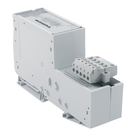
Page 39: Technical Data
DeviceNet Ifield supply ™ JDeviceNet Open Style Connector GND L GND L CAN H SHIELD CAN L V– Structure of a BL20-ECO gateway Figure 4-2: Structure of a BL20-ECO gateway FIeld bus Service Controller External RAM Module bus (External) Interface... -
Page 40: General Technical Data Of A Station
RS232 via PS2/ mini DIN female connector Ambient conditions Ambient temperature – t 0 to +55 °C / 32 to 131 °F Ambient – t -25 to +85 °C / 13 to 185 °F Store D301141 1211 - BL20-ECO DeviceNet™... - Page 41 Emitted interference according to according to EN 55 011 Class A, Group 1 EN 50 081-2 (Industry) Attention This device can cause radio disturbances in residential areas. Additional measures to suppress the disturbance are necessary. D301141 1211 - BL20-ECO DeviceNet™...
-
Page 42: Technical Data For The Push-In Tension Clamp Terminals
/ 0.0008 to 0.0023 inch / 25 to 16 AWG "f" with ferrules according to 0.25 to 1.5 mm / 0.0004 to 0.0023 inch / 30 to 16 AWG DIN 46228/1 (ferrules crimped gas- tight) D301141 1211 - BL20-ECO DeviceNet™... -
Page 43: Connection Possibilities At The Gateways
Figure 4-3: ™ DeviceNet female connector (top: connection level) Figure 4-4: ™ DeviceNet female connector (viewed from below) Figure 4-5: GND L ™ DeviceNet male connector on the gateway CAN H SHIELD CAN L V– D301141 1211 - BL20-ECO DeviceNet™... -
Page 44: Voltage Supply
Eco-Gateway for DeviceNet™ The shielding concept for the BL20-E-GW-DN is similar to that of the BL20-GWBR-DNET: Figure 4-6: Shielding connection, here for an BL20- GWBR-DNET Attention No compensating current should flow through the shielding. To achieve this, a reliable system of equipotential bonding must be installed. -
Page 45: Service Interface Connection
PC (top view) Table 4-5: BL20 gateway Sub-D-interface at the PC Pin assignment PS/2-socket PS/2- and SUB-D- interface DTR, DSR 4, 6 DATA – – n.c. (DATA2) n.c. (CLK2) D301141 1211 - BL20-ECO DeviceNet™... -
Page 46: Setting The Node-Id
Eco-Gateway for DeviceNet™ Setting the Node-ID ™ The setting of the MAC-ID for the BL20-ECO gateway for DeviceNet is done via the DIP switches 2 at the gateway. These DIP switches can be found under the gateway’s upper label. SERVICE... -
Page 47: Setting The Bit Rate
Setting the Bit Rate Setting the Bit Rate The gateway BL20-E-GW-DN offers 2 DIP switches for setting the bit rate (BR). Figure 4-11: DIP switches for setting the bit rate 4.6.1 DIP-Switch Settings DIP switch Bit rate autobaud 125 kBit/s... -
Page 48: Set Switch
Configuring the BL20 Station Using a Configuration Tool The configuration of a BL20 station is temporarily saved to the Temp-Required Configuration Memory when it is being configured with the aid of a configuration tool. To save this configuration as the reference configuration for the process data traffic in the Required Memory of the gateway, the following command must be carried out: SET_CFG _REQUEST (VSC100, Object Instance 2, Attribute No. -
Page 49: Reading-In Of Station Configuration Without Configuration Tool
3. 4.7.3 Reading-in of Station Configuration without Configuration Tool The current BL20 station configuration at the gateway is saved to the non-volatile Required Memory of the gateway using the SET Switch on the gateway, thus making it possible for the configuration to be ™... -
Page 50: Status Indicators/ Diagnostic Messages Gateway
Eco-Gateway for DeviceNet™ Status Indicators/ Diagnostic Messages Gateway The gateway transmits the following diagnostics: the status of the BL20 station, the communication via the internal module bus, the communication to CANopen and the status of the gateway. Diagnostic messages are displayed in two ways: via individual LEDs via the software of the respective host system (i. - Page 51 If the mains voltage is correctly connected, contact your Turck representative. Module-bus error Check the individual BL20 modules for correct mounting. Red flashing, Non-adaptable modification Compare the engineering of your BL20...
- Page 52 Green flashing, At least one input/output is slowly in the status "Idle State". At least one input/output has an error. Red flashing At least one input/output is in Faulted State. 4-16 D301141 1211 - BL20-ECO DeviceNet™...
-
Page 53: Connection To Automation Devices
– Offline Configuration of the BL20 Station..................16 – Online Mode ............................ 16 – Incorporating the BL20 Station in the Scan List of the DeviceNet™ Scanner ........ 17 – Mapping the Input and Output Data....................18 – Parameterization and Diagnostic of the BL20 Station ..............18 –... -
Page 54: Introduction
The modules with which BL20 is to communicate must comply with the ODVA specification and the communication profile described therein. This manual contains a description of the connection to the SLC 500 controller, and the 1747-SDN Scanner Module manufactured by Allen Bradley. -
Page 55: Electronic Data Sheet - Eds File
The EDS file 6827xxxVy_SP.eds provides the means for processing the selected instance of one module. The respective current version of the EDS file is available from TURCK. It is also possible to make an update by downloading the file from the TURCK Homepage: www.turck.com. -
Page 56: Mapping Of Process Data
Mapping of Process Data The process image of the BL20 gateway is depicted in WORD format (16 bit). The process data of successive modules of the same type, with process data of less than 1 word, are grouped together until 16 bits of process data is reached. -
Page 57: Data Mapping For An Example Station
Output Data (WORD Format) (Bit 15...→ ... 0) (Word No.) Control Register of the Gateway (Mapping can be disabled via VSC100, instance 2., attr. 133 (85h), page 10-11) F15, F14, ... F1, F0 L1, L0, I1, I0;H1, H0; G1, G0 D301141 1211 - BL20-ECO DeviceNet™... -
Page 58: Diagnostic Options
10-10) Module diagnostics from the module actually referenced by the round robin mechanism. The scheduled diagnostic data is placed at the end of the input data and after the summarized diagnostic data (see page 5-6). D301141 1211 - BL20-ECO DeviceNet™... -
Page 59: Status Register Of The Gateway
Table 5-5: Status Register Error Codes – gateway. OUTPUTS NOT PROCESSING The BL20 outputs are no longer controlled by the process data of an I/O connection. MODULE LIST WARNING The current module list at the gateway has been modified, meaning: a module has been added, a module has been pulled or a module has been placed on a slot, which was pre-configured as empty. - Page 60 11h to 1Fh Reserved MODULE ID UNKNOWN At least one module on the BL20 station is unknown, meaning, it is neither represented by an existing Vendor Specific Classes nor is it listed in the EDS file. Nevertheless, the module is taking part in process data exchange.
-
Page 61: Control Register Of The Gateway
84h to EFh Reserved MODULEBUS SHUTDOWN The transmission of data via the module bus is stopped. The reaction of the individual BL20 modules depends on their respective parameterization. RESTART MODULE BUS The transmission of data via the module bus will be started. -
Page 62: Connection To The Controller Slc 500 From Allen Bradley
Setting Up Communications with the Software Tool "RSLinx" The Allen Bradley software tool "RSNetworx" (version 3.00.00) from Rockwell Automation is used to configure the connection of a BL20 gateway with an Allen Bradley SLC 500. Before a connection to this ™... - Page 63 The node is configured in the window that opens, which means for example, that the data transmission rate, the serial interface, the node address as well as the baud rate are entered. Figure 5-4: Configuring the 1770-KFD 5-11 D301141 1211 - BL20-ECO DeviceNet™...
-
Page 64: Configuring The Devicenet Network With Rsnetworx
DeviceNet network in RSLinx ™ 5.7.2 Configuring the DeviceNet Network with RSNetworx ™ The BL20 gateway is integrated in to the DeviceNet network using the configuration software RSNetworx from Allen Bradley. Figure 5-6: The Software RSNetworx 5-12 D301141 1211 - BL20-ECO DeviceNet™... -
Page 65: Reading In The Eds File
Open the EDS Wizard using the "Tools → EDS Wizard" command. Figure 5-7: Opening the EDS Wizard Click the "Register an EDS file(s)" button to add the EDS file to be registered to the program’s database. Figure 5-8: Registering the EDS File 5-13 D301141 1211 - BL20-ECO DeviceNet™... -
Page 66: Offline Configuration Of The Network
Connection to Automation Devices The BL20 gateway appears in the hardware catalogue of the software following correct registering of the EDS file. Figure 5-9: Hardware catalog with BL20 gateway Offline Configuration of the Network The network nodes are selected from the hardware catalogue using the drag-and-drop operation or by double-clicking on the product name. -
Page 67: Configuration Of The Devicenet Gateway And The Connected Bl20 Station
The gateway parameters are set in the "Device Parameters" tabbed page, where the gateway and the connected modules can be parameterized offline. Figure 5-12: Setting the Gateway Parameters The gateway parameters occupy the lines 1 to 27". The following IDs are reserved for the BL20 I/O modules. 5-15 D301141 1211 - BL20-ECO DeviceNet™... -
Page 68: Offline Configuration Of The Bl20 Station
Connection to Automation Devices Offline Configuration of the BL20 Station The offline configuration of the BL20 station is also carried out in this tabbed page. Double-click the text "EMPTY BASE TERMINAL". The respective I/O modules can be selected from the pull-down menu that opens. -
Page 69: Incorporating The Bl20 Station In The Scan List Of The Devicenet Scanner
Incorporating the BL20 Station in the Scan List of the DeviceNet Scanner In order for the 1747-SDN Scanner Module of the SLC 500 to be able to communicate with the BL20 gateway the BL20 gateway has to be included in the scan list of the 1747-SDN Scanner Module. -
Page 70: Mapping The Input And Output Data
Double-click the BL20 gateway icon to open the "BL20-E-GW-DN" window. The parameters of all the modules in the BL20 station are contained in the tabbed page "Parameters". The lines 1 to 27 relate to the gateway, thereafter the BL20 modules follow in the order in which they were plugged in the station. -
Page 71: Status Register And Control Register Of The Gateway
Status Register and the Control Register as well as their bit assignments. Table 5-6: Status Register Message Codes shows the message codes for Bit 0 to Bit 7 of the Status Register. 5-19 D301141 1211 - BL20-ECO DeviceNet™... -
Page 72: Parameterization Of The Bl20 Station
Double-click the line with the parameters of the respective module to open the window with the parameter settings. Figure 5-21: Setting the parameters of a BL20 module Altered parameter settings are loaded in to the BL20 gateway by clicking the appropriate button. 5-20 D301141 1211 - BL20-ECO DeviceNet™... - Page 73 Connection to the Controller SLC 500 from Allen Bradley 5-21 D301141 1211 - BL20-ECO DeviceNet™...
- Page 74 Connection to Automation Devices 5-22 D301141 1211 - BL20-ECO DeviceNet™...
-
Page 75: Guidelines For Station Planning
C-Rail (Cross Connection) ........................7 6.3.5 Direct Wiring of Relay Modules ......................9 Protecting the Service Interface on the Gateway................10 Plugging and Pulling Electronics Modules..................10 Extending an Existing Station......................10 Firmware Download........................10 D301141 1211 - BL20-ECO DeviceNet™... -
Page 76: Module Arrangement
Module Arrangement 6.1.1 Random Module Arrangement The arrangement of the I/O modules within a BL20 station can basically be chosen at will. Nevertheless, it can be useful with some applications to group certain modules together. Note A mixed usage of gateways of the BL20 ECO and the BL20 standard product line and I/O modules of both product lines (base modules with tension clamp terminals) is possible without any problems. -
Page 77: Maximum System Extension
Right to the Bus Refreshing module, the sum of the modules’ current consumptions can amount to 1,5 A. Attention The usage of a Bus Refreshing module BL20-BR-24VDC-D is supported in order to enlarge a station. But: Using the Bus Refreshing module causes a galvanic coupling of V+/ V- and the supplied... - Page 78 35 mA BL20-2AI-PT/NI-2/3 45 mA BL20-2AI-THERMO-PI 45 mA BL20-4AI-U/I 30 mA BL20-2DO-24VDC-0.5A-P 32 mA BL20-2DO-24VDC-0.5A-N 32 mA BL20-2DO-24VDC-2A-P 33 mA BL20-2DO-120/230VAC-0.5A 35 mA BL20-4DO-24VDC-0.5A-P 30 mA BL20-E-8DO-24VDC-0.5A-P 15 mA BL20-E-16DO-24VDC-0.5A-P 25 mA BL20-16DO-24VDC-0.5A-P 120 mA D301141 1211 - BL20-ECO DeviceNet™...
- Page 79 39 mA BL20-2AO-I(0/4...20MA) 40 mA BL20-2AO-U(-10/0...+10VDC) 43 mA BL20-2DO-R-NC 28 mA BL20-2DO-R-NO 28 mA BL20-2DO-R-CO 28 mA BL20-1CNT-24VDC 40 mA BL20-1RS232 140 mA BL20-1RS485/422 60 mA BL20-1SSI 50 mA BL20-E-1SWIRE 60 mA BL20-E-2RFID-S 30 mA D301141 1211 - BL20-ECO DeviceNet™...
-
Page 80: Power Supply
The number of BL20 modules, which can be supplied via the internal module bus by the gateway or a Bus Refreshing module depends on the modules’ nominal current consumptions at the module bus... -
Page 81: C-Rail (Cross Connection)
Access to the C-rail is possible with the help of base modules with a C in their designation (for example, BL20-S4T-SBCS). The corresponding connection level is indicated on these modules by a thick black line. The black line is continuous on all I/O modules. On power distribution modules, the black line is only above the connection 24. - Page 82 C-rails can be used for a common voltage supply when relay modules are planned. To accomplish this, the load voltage is connected to a Power Feeding module with the BL20-P4x-SBBC base module with tension clamp or screw connection. All the following relay modules are then supplied with power via the C-rail.
-
Page 83: Direct Wiring Of Relay Modules
SBCS SBCS SBCS Cross-connecting relay module roots is achieved by the use of jumpers. The corresponding wiring diagram including the jumpers can be found the manuals for BL20 I/O modules (German D300716, English D300717). 6.3.5 Direct Wiring of Relay Modules As well as the options mentioned above, relay modules can be wired directly. -
Page 84: Protecting The Service Interface On The Gateway
BL20 enables the pulling and plugging of electronics modules without having to disconnect the field wiring. The BL20 station remains in operation if an electronics module is pulled. The voltage and current supplies as well as the protective earth connections are not interrupted. -
Page 85: Guidelines For Electrical Installation
7.1.5 Cable Types............................3 Potential Relationships........................4 7.2.1 Potential-Free Installation........................4 – General .............................. 4 – For BL20-stations with BL20-E-GW-DN ................... 4 Electromagnetic Compatibility (EMC)....................6 7.3.1 Ensuring Electromagnetic Compatibility ....................6 7.3.2 Grounding of Inactive Metal Components ................... 6 7.3.3... -
Page 86: General Notes
The cable duct joints must be electrically connected and the cable ducts must be earthed. Warning Observe all valid guidelines concerning internal and external lightning protection and grounding specifications when routing cables outside of buildings. D301141 1211 - BL20-ECO DeviceNet™... -
Page 87: Lightning Protection
Please refer to the DeviceNet™ specifications (ODVA Spec. Rel. V2.0, Vol. 1) or the ODVA homepage: www.odva.org. The following diagram shows the schematic construction of a "round" DeviceNet™ cable: Figure 7-2: ΤΜ DeviceNet cable schematic CAN_H CAN_L Shield D301141 1211 - BL20-ECO DeviceNet™... -
Page 88: Potential Relationships
Guidelines for Electrical Installation Potential Relationships The potential relationship of a DeviceNet™ system realized with BL20 modules is characterized by the following: The system’s power supply to the gateway, I/O modules and the field level is connected to the gateway. - Page 89 Open Style Connector (see Figure 7-5:). Figure 7-5: Bus Refreshing Potential free module Gateway I/O module installation with field bus BL20-E-GW-DN data and Bus V+ (U ) Refreshing module V- (GND) field bus logic cable D301141 1211 - BL20-ECO DeviceNet™...
-
Page 90: Electromagnetic Compatibility (Emc)
7.3.1 Ensuring Electromagnetic Compatibility The EMC of BL20 modules is guaranteed when the following basic rules are adhered to: Correct and large surface grounding of inactive metal components. Correct shielding of cables and devices. Proper cable routing – correct wiring. -
Page 91: Protection Against High Frequency Interference Signals
Remove the isolating layer from all painted, anodized or isolated metal components at the connection point. Protect the connection point against corrosion (for example with grease; caution: use only suitable grease). D301141 1211 - BL20-ECO DeviceNet™... -
Page 92: Emc Compliant Cabinet Installation
The protective conductor terminal block must be connected to the protective conductor rail. E Protective conductor system cable (grounding point) The cable must be connected over a large surface area with the protective conductor system. D301141 1211 - BL20-ECO DeviceNet™... -
Page 93: Shielding Of Cables
A further possibility is a double-shielded cable (galvanically separated), whereby the innermost shield is connected on one side and the outermost shield is connected on both sides. D301141 1211 - BL20-ECO DeviceNet™... -
Page 94: Potential Compensation
The compensation cable must be made of copper or zinc coated steel. The compensation cable must be connected to the protective conductor over a large surface area and must be protected against corrosion. 7-10 D301141 1211 - BL20-ECO DeviceNet™... -
Page 95: Switching Inductive Loads
Protection against Electrostatic Discharge (ESD) Attention Electronics modules and base modules are at risk from electrostatic discharge when disassembled. Avoid touching the bus connections with bare fingers as this can lead to ESD damage. 7-11 D301141 1211 - BL20-ECO DeviceNet™... - Page 96 Guidelines for Electrical Installation 7-12 D301141 1211 - BL20-ECO DeviceNet™...
-
Page 97: Integration Of Technology Modules In Devicenet
Integration of Technology Modules in DeviceNet™ Counter module, BL20-1CNT-24VDC ....................2 8.1.1 Process Input for Count Mode ......................2 8.1.2 Process Output for Count Mode ......................2 8.1.3 Process Input for Measurement Mode ....................4 8.1.4 Process Output for Measurement Mode ....................5 RSxxx Modules .......................... -
Page 98: Counter Module, Bl20-1Cnt-24Vdc
X = reserved 8.1.2 Process Output for Count Mode The process output data is the data that is output from the PLC via the gateway to the BL20- 1CNT-24VDC module. The BL20-1CNT-24VDC module allows some parameters to be modified during operation. - Page 99 1" or "Reference value 2" X = reserved Structure of the data bytes in the DeviceNet™ fieldbus with "Function and Behavior of DO1/DO2" Figure 8-3: PDOut with "Function and Behavior of DO1/ DO2" X = reserved D301141 1211 - BL20-ECO DeviceNet™...
-
Page 100: Process Input For Measurement Mode
8.1.3 Process Input for Measurement Mode Process input data is data from the connected field device that is transmitted via the BL20-1CNT-24VDC module to the PLC. This is transferred in an 8-byte format as follows: Four bytes are used to contain the measured values. -
Page 101: Process Output For Measurement Mode
Counter module, BL20-1CNT-24VDC 8.1.4 Process Output for Measurement Mode The process output data is the data that is output from the PLC via the gateway to the BL20- 1CNT-24VDC module. The BL20-1CNT-24VDC module allows some parameters to be modified during operation. - Page 102 Structure of the data bytes in the DeviceNet™ fieldbus with "Function of DO1 set" set: Figure 8-6: PDOut with "Function of DO1" X = reserved ΤΜ Structure of the data bytes in the DeviceNet fieldbus with "Integration Time" set: Figure 8-7: PDOut with "Integration time" X = reserved D301141 1211 - BL20-ECO DeviceNet™...
-
Page 103: Rsxxx Modules
The meaning of the numerical values is explained in the description of the attributes, Classes and Instances of the DeviceNet™-Gateway, chapter Note The description of the process input and output data of the modules BL20-1RS232 and BL20- 1RS485/422 is identical. 8.2.1 Process Input Data ACTIVE MODE = "1byte ctrl/status header" Figure 8-8: Process input data ACTIVE MODE = "2byte ctrl/status header"... -
Page 104: Process Output Data
The meaning of the numerical values is explained in the description of the attributes. ACTIVE MODE = "1byte ctrl/status header" Figure 8-10: Process output data ACTIVE MODE = "2byte ctrl/status header" Figure 8-11: Process output data D301141 1211 - BL20-ECO DeviceNet™... - Page 105 The TXBUF FLUSH bit is used for clearing the transmit buffer. If STATUS RESET CONTROL = 1: A request with TXBUF FLUSH = 1 will be ignored. If STATUS RESET CONTROL = 0: With TXBUF FLUSH = 1 The receive buffer is cleared. D301141 1211 - BL20-ECO DeviceNet™...
-
Page 106: Process Input Data
These four bits transfer the status bits of the SSI encoder with the status messages of Meaning of data the SSI module. SSI_STS2 bits 0 to 3 (Byte 2) With some SSI encoders, the status bits are transferred together with the position value. SSI_STS1 SSI_STS0 8-10 D301141 1211 - BL20-ECO DeviceNet™... -
Page 107: Process Output Data
SSI-Module 8.3.2 Process Output Data Figure 8-13: Process output data 8-11 D301141 1211 - BL20-ECO DeviceNet™... -
Page 108: Swire Modules
The field input data is transferred from the connected SWIRE-BUS to the BL20-E-1SWIRE module. The process input data is the data that is transferred by the BL20-E-1SWIRE module via a gateway to the PLC. The transfer is carried out in 8-byte format. 4 bits are reserved for each SWIRE slave. The following... - Page 109 (input byte 1/bit 3) to the feedback interface. The information is provided as status information in the PLC for the user. ON LINE ON LINE Status of slave x: Everything o.k. OFF LINE OFF LINE Status of slave x: Slave diagnostics message present 8-13 D301141 1211 - BL20-ECO DeviceNet™...
-
Page 110: Process Output Data
8.4.2 Process Output Data Field output data is output from an BL20-E-1SWIRE module to a field device. The process output data is the data that is transferred by the PLC via a gateway to the BL20-E-1SWIRE module. The transfer is carried out in 8-byte format. -
Page 111: Rfid Modules
RFID Modules RFID Modules Note For all information concerning the RFID communication interfaces see the special RFID documentation (TURCK document D101642 which can be downloaded from www.turck.com). 8-15 D301141 1211 - BL20-ECO DeviceNet™... - Page 112 Integration of Technology Modules in DeviceNet™ 8-16 D301141 1211 - BL20-ECO DeviceNet™...
-
Page 113: Bl20-Approvals For Zone 2/ Division
BL20-Approvals for Zone 2/ Division 2 Note The Zone 2 - approval certificates for BL20 can be found in a separate manual for approvals D301255 on www.turck.de. D301141 1211 - BL20-ECO DeviceNet™... - Page 114 BL20-Approvals for Zone 2/ Division 2 D301141 1211 - BL20-ECO DeviceNet™...
-
Page 115: 10 Appendix
– Analog Versatile Module Class (VSC118, 76h)................71 – SWIRE Module Class (VSC121, 79h)....................74 – RFID-S Module Class (VSC124, 7Ch) .....................78 10.2 Nominal Current Consumption and Power Loss ................80 10.3 Power Loss of the Modules ......................82 10-1 D301141 1211 - BL20-ECO DeviceNet™... -
Page 116: Classes And Instances Of The Devicenet™-Gateway
Appendix 10.1 Classes and Instances of the DeviceNet™-Gateway 10.1.1 DeviceNet™ Standard Classes The BL20 gateway supports the following DeviceNet™ Standard Classes in accordance with ODVA DeviceNet™ specification Vol. 1 Rel. V2.0. Table 10-1: Class Name Description DeviceNet™ Code Standard Classes dec. -
Page 117: 10.1.2 Vsc-Vendor Specific Classes
Power Supply Module Class, Describes the power distribution modules page 10-18 104 (68h) Digital Input Module Class, Describes the modules of the type BL20-*DI-* page 10-20 105 (69h) Digital Output Module Class, Describes the modules of the type BL20-*DO-* page 10-22... - Page 118 Class Code Name Description Table 10-2: VSC-Vendor dec. (hex.) Specific Classes 117 (75h) Digital Versatile Module No BL20-modules available in this class. Class, page 10-67 118 (76h) Analog Versatile Module Describes modules of the type BL20-4AI-U/I Class, page 10-71 121 (79h) SWIRE Module Class, Describes modules of the type BL20-E-SWIRE.
-
Page 119: Class Instance Of The Vsc
102 (66h) # of instances USINT Contains the number of Object Instances created in this class. 103 (67h) Max. class USINT Contains the number of the last Class attribute Attribute to be implemented. 10-5 D301141 1211 - BL20-ECO DeviceNet™... -
Page 120: Gateway Class (Vsc 100, 64H)
Appendix Gateway Class (VSC 100, 64h) The Gateway Class contains all the parameters that concern the BL20 system and the gateway. Class Instance Note Please refer to paragraph "Class Instance of the VSC", page 9-6, for the description of the class instance for the VSC. - Page 121 Only the most significant status is saved to the Status Register of the transmitted I/O data. The "status array register" makes it possible to read all the momentary status data. ARRAY OF: USINT STAT (status information) 10-7 D301141 1211 - BL20-ECO DeviceNet™...
- Page 122 CFG MISMATCH(1): The station configuration saved to the non-volatile memory does not match the temporary configuration. Module SET MODIFIED(2): The momentary station configuration does not match the temporary configuration. 10-8 D301141 1211 - BL20-ECO DeviceNet™...
- Page 123 SWITCH IO OFF (1): The gateway switches off the outputs of the modules. SWITCH IO HOLD (2): The gateway makes no further changes to the data of the I/O modules. The outputs are held. 10-9 D301141 1211 - BL20-ECO DeviceNet™...
- Page 124 Monitoring of supply voltage V+ of (7Ah) field bus DeviceNet: 0 = V+ not in the required range (< 11 V DC) 1 = V+ in the required range (>11 V DC) 123 -131 reserved (7Bh - 83h) 10-10 D301141 1211 - BL20-ECO DeviceNet™...
- Page 125 Enables/disables the control register (8Bh) register USINT mapping in the process output data. 0 = 0 bytes (control register not mapped in process output data) 1 = 2 bytes (control register mapped in process output data) 10-11 D301141 1211 - BL20-ECO DeviceNet™...
-
Page 126: Terminal Slot Class (Vsc 101, 65H)
It is not responding to data transmitted or received via I/O Connection Messages. PROCESSING (1): A BL20 module, recognized by the fieldbus is occupying a slot. Data transfer is taking place with the other fieldbus devices via I/ O Connection Messages. - Page 127 Module output bit UINT States the number of output bits count (consumed bits) of the module. 108 (6Ch) Module USINT Contains the Submode ID of the BL20 SUBMODE module. 109 (6Dh) Module group USINT States the number of internal groups of count the module.
-
Page 128: Process Data Class (Vsc102, 66H)
Instance. 102 (66h) Standard packed ARRAY OF Output process data, 16-bit aligned, process output WORD compressed. data 103 (67h) Process data byte USINT The number of bytes that are exchanged count with this Instance. 10-14 D301141 1211 - BL20-ECO DeviceNet™... - Page 129 Contains the number of summarized summarized diags diagnostic bytes. Changes become valid after a start-up! 108 (6Ch) I-MAP USINT Contains the number of scheduled scheduled diags diagnostics bytes. Changes become valid after a start-up! 10-15 D301141 1211 - BL20-ECO DeviceNet™...
- Page 130 Values 0 to 200 Bytes (only even byte (68h) interface length values allowed). 0 = disabled Required min. length depends on RFID commands used. (For further information see the special RFID documentation, document number D101642.) 10-16 D301141 1211 - BL20-ECO DeviceNet™...
- Page 131 Object Instance 8, dec. (hex.) RFID CIP support 104 (68h) RFID CIP support USINT 0 = disabled 1 = enabled: = access via RFID CIP (expl. msg. read/write) to VSC120, attributes 113 and 114, page 10-79 10-17 D301141 1211 - BL20-ECO DeviceNet™...
-
Page 132: Power Supply Module Class (Vsc103, 67H)
– 0x1F: analog volt./curr. mod. – 0x22: counter/incr. encoder 32bit – 0x28: SSI interface – 0x31: starter, mechanical – 0x32: starter, electronical – 0x41: RS232 mod. – 0x42: RS485/RS422 mod. – 0x51: CVI mod. – etc. 10-18 D301141 1211 - BL20-ECO DeviceNet™... - Page 133 WORD Contains the diagnostic information of the module. WORD: Bit for bit assignment according to module specification. 112 (70h) Module registered ENUM Contains the index numbers specified in all index USINT the module lists. 10-19 D301141 1211 - BL20-ECO DeviceNet™...
-
Page 134: Digital Input Module Class (Vsc104, 68H)
Describes the module type: (6Bh) USINT see attribute 107 (6Bh) on page 10-18 Module command ARRAY The control interface of the BL20 module. (6Ch) interface ARRAY OF: BYTE: Control byte sequence Module response ARRAY Response interface of the BL20 module. - Page 135 Params DWORD Contains the parameters of the module. (73h) DWORD: Bit for bit assignment according to module specification. Module registered ENUM Contains the index numbers specified in all (74h) index USINT the module lists. 10-21 D301141 1211 - BL20-ECO DeviceNet™...
-
Page 136: Digital Output Module Class (Vsc105, 69H)
Describes the module type: see attribute USINT 107 (6Bh) on page 10-18 108 (6Ch) Module command ARRAY The control interface of the BL20 module. interface ARRAY OF: BYTE: Control byte sequence Module response ARRAY Response interface of the BL20 module. - Page 137 Params DWORD Contains the parameters of the module. (73h) DWORD: Bit for bit assignment according to module specification. Module registered ENUM Contains the index numbers specified in all (74h) index USINT the module lists. 10-23 D301141 1211 - BL20-ECO DeviceNet™...
-
Page 138: Analog Input Voltage Module Class (Vsc106, 6Ah)
Describes the module type: see attribute USINT 107 (6Bh) on page 10-18 108 (6Ch) Module command ARRAY The control interface of the BL20 module. interface ARRAY OF: BYTE: Control byte sequence 109 (6Dh) Module response ARRAY Response interface of the BL20 module. - Page 139 BYTE mode: Bit0: Voltage mode: 0 =0...10V 1 =-10V...+10V Bit 1: Value representation 0 =Integer (15Bit + sign) 1 =12Bit (left-justified) Bit 2: Diagnostic: 0 = enable 1 = disable Bit 3 to 7: reserved 10-25 D301141 1211 - BL20-ECO DeviceNet™...
-
Page 140: Analog Output Voltage Module Class (Vsc107, 6Bh)
Describes the module type: see attribute USINT 107 (6Bh) on page 10-18 108 (6Ch) Module command ARRAY The control interface of the BL20 module. interface ARRAY OF: BYTE: Control byte sequence 109 (6Dh) Module response ARRAY Response interface of the BL20 module. -
Page 141: Analog Input Current Module Class (Vsc108, 6Ch)
This Class contains all information and parameters for analog input modules (current). Class Instance Note Please refer to paragraph sectiont „Class Instance of the VSC“, page 10-5, for the description of the class instances for VSC. 10-27 D301141 1211 - BL20-ECO DeviceNet™... - Page 142 1, attribute 127 for channel 8. BYTE diag: Bit 0: 0 = ok 1 = measurement value range error Bit 1: 0 =ok 1 =open circuit (only measurement range 4 to 20 mA) Bit 2 to 7: reserved 10-28 D301141 1211 - BL20-ECO DeviceNet™...
- Page 143 0 = 0 to 20 mA 1 = 4 to 20 mA Bit 1: Value representation: 0 =Integer (15 Bit + sign) 1 =12 Bit (left-justified) Bit 2: Diagnostic: 0 = enable 1 = disable Bit 3 to 7:reserved 10-29 D301141 1211 - BL20-ECO DeviceNet™...
-
Page 144: Analog Output Current Module Class (Vsc109, 6Dh)
BYTE mode: Bit 0: Current mode: 0 = 0 to 20 mA 1 = 4 to 20 mA Bit 1: Value representation: 0 =Integer (15Bit + sign) 1 =12Bit (left-justified) Bit 2 to 7:reserved 10-30 D301141 1211 - BL20-ECO DeviceNet™... - Page 145 1 to 8 of the analog output modules. Only those channels are supported that are defined in attribute 111, "Number of supported channels". Attribute 136 contains the data for channel 1, attribute 143 for channel 8. 10-31 D301141 1211 - BL20-ECO DeviceNet™...
-
Page 146: Analog Input Pt100/Ni Module Class (Vsc110, 6Eh)
Describes the module type: see attribute USINT 107 (6Bh) on page 10-18 108 (6Ch) Module command ARRAY The control interface of the BL20 module. interface ARRAY OF: BYTE: Control byte sequence 109 (6Dh) Module response ARRAY Response interface of the BL20 module. - Page 147 1, attribute 127 for channel 8. BYTE diag: Bit 0: 0 = ok 1 = measurement value range error Bit 1: 0 = ok 1 = open circuit Bit 2: 0 = ok 1 = short-circuit 10-33 D301141 1211 - BL20-ECO DeviceNet™...
- Page 148 Bit 2: Diagnose: 0 = release 1 = block Bit 3:Channel: 0 = activate channel 1 = deactivate channel Bit 4: Measurement mode: 0 = 2-wire 1 = 3-wire Bit 5 to 7: reserved 10-34 D301141 1211 - BL20-ECO DeviceNet™...
- Page 149 8: PT1000, -200...850 °C 9: PT1000, -200...150 °C 10: NI1000, -60...250 °C 11: NI1000, -60...150 °C 12: resistance: 0...100 Ω 13: resistance: 0...200 Ω 14: resistance: 0...400 Ω 15: resistance: 0...1000 Ω 16 to 255: reserved 10-35 D301141 1211 - BL20-ECO DeviceNet™...
-
Page 150: Analog Input Thermo Module Class (Vsc111, 6Fh)
Describes the module type: see attribute USINT 107 (6Bh) on page 10-18 108 (6Ch) Module command ARRAY The control interface of the BL20 module. interface ARRAY OF: BYTE: Control byte sequence 109 (6Dh) Module response ARRAY Response interface of the BL20 module. - Page 151 Bit 1: value representation: 0 =Integer (15Bit + sign) 1 =12Bit (left-justified) Bit 2: Diagnose: 0 = release 1 = block Bit 3:Channel: 0 = activate channel 1 = deactivate channel Bit 4 to 7: reserved 10-37 D301141 1211 - BL20-ECO DeviceNet™...
- Page 152 4: Type N -270...1300 °C 5: Type R -50...1760 °C 6: Type S -50...1540 °C 7: Type T -270...400 °C 8: +/-50 mV 9: +/-100 mV 10: +/-500 mV 11: +/-1000 mV 12 to 255: reserved 10-38 D301141 1211 - BL20-ECO DeviceNet™...
-
Page 153: Counter1 Module Class (Vsc112, 70H)
Describes the module type: see attribute USINT 107 (6Bh) on page 10-18 108 (6Ch) Module command ARRAY The control interface of the BL20 module. interface ARRAY OF: BYTE: Control byte sequence 109 (6Dh) Module response ARRAY Response interface of the BL20 module. - Page 154 1 = short- circuit/open circuit Bit9: 0 = ok 1 = short-circuit in sensor power supply 24 V DC Bit10: 0 = ok 1 = sensor pulse wrong Bit11: 0 = ok 1 = integration time wrong 10-40 D301141 1211 - BL20-ECO DeviceNet™...
- Page 155 No. 113 BASIC MODE. 115 (73h) Digital input DI ENUM Defines if the digital input of the module USINT will be inverted or not. USINT digital input DI: – 0:normal – 1:inverted – 2 to 255:reserved 10-41 D301141 1211 - BL20-ECO DeviceNet™...
- Page 156 Defines the number of pulses per revolution revolution. Pulses per revolution 125 (7Dh) Fault value DO1 BOOL Defines the substitute value of the digital output DO1. Fault value DO1: FALSE:0 = off, 0V TRUE: 1 = on, 24V 10-42 D301141 1211 - BL20-ECO DeviceNet™...
- Page 157 – 1: CNT: on when count value ≥ reference value – 2: CNT: on when count value ≤ reference value – 3: CNT: pulse when count value = reference value – 4 to 255:reserved 10-43 D301141 1211 - BL20-ECO DeviceNet™...
- Page 158 Direction input B: – FALSE: normal – TRUE: inverted 135 (87h) Group diagnostics G/S BOOL Defines if the group diagnostic will be transmitted to the gateway or not. Group diagnostic: – FALSE: release – TRUE: block 10-44 D301141 1211 - BL20-ECO DeviceNet™...
- Page 159 (parameter name of the counter: CPU/ master STOP): – 0: turn off DO1 – 1: proceed with operating mode – 2: DO1 switch to Fault Value – 3: DO1 hold last value – 4 to 255:reserved 10-45 D301141 1211 - BL20-ECO DeviceNet™...
-
Page 160: Rs232 Module Class (Vsc114, 72H)
Describes the module type: see attribute USINT 107 (6Bh) on page 10-18 108 (6Ch) Module command ARRAY The control interface of the BL20 module. interface ARRAY OF: BYTE: Control byte sequence 109 (6Dh) Module response ARRAY Response interface of the BL20 module. - Page 161 1 = "parameter error": The set parameter values are not supported. – Bit 4: 0 = ok 1 = "hardware failure": The module has to be replaced, e.g. EEPROM or UART may be defect. 10-47 D301141 1211 - BL20-ECO DeviceNet™...
- Page 162 RX count has been transmitted together with the last data segment of the process input data. RX count acknowledge is an acknowledge for the successful transmission of the data segment with RX count. 10-48 D301141 1211 - BL20-ECO DeviceNet™...
- Page 163 ARRAY OF Defines the transmit-data (0...7) BYTE 125 (7Dh) TX data and ARRAY OF Defines the data to be transmitted via release BYTE RS232 (0...7) + transmission is released/ charged immediately 126 (7Eh) reserved 10-49 D301141 1211 - BL20-ECO DeviceNet™...
- Page 164 7 bytes of user data are available. 1 = "2byte ctrl/status header": The diagnostic data are part of the process input data, 6 bytes of user data are available. 10-50 D301141 1211 - BL20-ECO DeviceNet™...
- Page 165 135 (87h) XON character USINT XON character This sign is used to start the data transfer to the data terminal equipment (DTE) with the activation of the software handshake. 0 - 255 default: 17/ 11h 10-51 D301141 1211 - BL20-ECO DeviceNet™...
- Page 166 136 (88h) XOFF character USINT XOFF character This sign is used to stop the data transfer to the data terminal equipment (DTE) with the activation of the software handshake. (0 - 255) default: 19/ 13h 10-52 D301141 1211 - BL20-ECO DeviceNet™...
-
Page 167: Rs485/422 Module Class (Vsc115, 73H)
Describes the module type: see attribute USINT 107 (6Bh) on page 10-18 108 (6Ch) Module command ARRAY The control interface of the BL20 module. interface ARRAY OF: BYTE: Control byte sequence 109 (6Dh) Module response ARRAY Response interface of the BL20 module. - Page 168 1 = "parameter error": The set parameter values are not supported. – Bit 4: 0 = ok 1 = "hardware failure": The module has to be replaced, e.g. EEPROM or UART may be defect. 10-54 D301141 1211 - BL20-ECO DeviceNet™...
- Page 169 RX count has been transmitted together with the last data segment of the process input data. RX count acknowledge is an acknowledge for the successful transmission of the data segment with RX count. 10-55 D301141 1211 - BL20-ECO DeviceNet™...
- Page 170 EEPROM or UART may be defect. – Bit 5: 0 = ok 1 = "handshake error": The DTE connected to the module does not answer a XOFF or RTS handshake. This may cause a overflow in the internal receive-buffer. 10-56 D301141 1211 - BL20-ECO DeviceNet™...
- Page 171 10 = 38400 bps 11 = 57600 bps 12 = 115200 bps 15 = reserved) 130 (82h) Disable BOOL 0 = "released": diagnostics The diagnostic function is activated. 1 = "blocked": The diagnostic function is deactivated. 10-57 D301141 1211 - BL20-ECO DeviceNet™...
- Page 172 (DTE) with the activation of the software handshake. (0 - 255) default: 19/ 13h 137 (89h) RS××× mode ENUM 0 = "RS422": USINT Parameterization as 422 1 = "RS485": Parameterization as 485 10-58 D301141 1211 - BL20-ECO DeviceNet™...
-
Page 173: Ssi Module Class (Vsc116, 74H)
Describes the module type: see attribute USINT 107 (6Bh) on page 10-18 108 (6Ch) Module command ARRAY The control interface of the BL20 module. interface ARRAY OF: BYTE: Control byte sequence 109 (6Dh) Module response ARRAY Response interface of the BL20 module. - Page 174 Bit 7: – 0 = The SSI encoder is read cyclically. – 1 = "SSI communication suspended" Communication with the SSI encoder is stopped as STOP = 1 (process output) or ERR_PARA = 1. 10-60 D301141 1211 - BL20-ECO DeviceNet™...
- Page 175 (REG_SSI_POS) = (REG_CMP2) since the last reset. – 1 = "CMP2 flag set" The contents of the registers match: (REG_SSI_POS) = (REG_CMP2). This marker must be reset with bit 12 of the "Control" attribute. 10-61 D301141 1211 - BL20-ECO DeviceNet™...
- Page 176 – 1 = "control register write accepted" The writing of user data for process output to the register addressed with "Address write register" in the process output data could be executed successfully. 10-62 D301141 1211 - BL20-ECO DeviceNet™...
- Page 177 – 0 = Default status, i.e. reset of Bit 9 of the "Diagnostics and status" attribute not active. – 1 = "clear CMP1 flag" Reset of bit 9 of the "Diagnostics and status" attribute active. 10-63 D301141 1211 - BL20-ECO DeviceNet™...
- Page 178 The structure contains both parts: execute UINT – Address of the register to be written. DWORD – Value to be written. The write operation is executed without checking whether a write job is already present. 10-64 D301141 1211 - BL20-ECO DeviceNet™...
- Page 179 0 = ZERO test of data cable. 1 = "disable SSI error detection" After the last valid bit, a ZERO test of the data cable is not carried out. Bit 6 to 15: reserved 10-65 D301141 1211 - BL20-ECO DeviceNet™...
- Page 180 INVALID BITS LSB. The invalid bits on the MSB side are zeroed by masking the position value. I NVALID BITS MSB + INVALID BITS LSB must always be less than FRAME LENGTH. Default: 0 = 0hex 10-66 D301141 1211 - BL20-ECO DeviceNet™...
-
Page 181: Digital Versatile Module Class (Vsc117, 75H)
Describes the module type: see attribute USINT 107 (6Bh) on page 10-18 108 (6Ch) Module command ARRAY The control interface of the BL20 module. interface ARRAY OF: BYTE: Control byte sequence 109 (6Dh) Module response ARRAY Response interface of the BL20 module. - Page 182 Short circuit DWORD This attribute contains diagnosis sensor error_2 information about sensor short-circuits (according to channels). 123 (7Bh) Cable error_1 DWORD This attribute contains diagnosis information about a wire break (channel 1 to 32). 10-68 D301141 1211 - BL20-ECO DeviceNet™...
- Page 183 Enables the high side output driver of output driver_2 channels (channel 33 to 64). 141 (8Ch) Enable low side DWORD Enables the low side output driver of output driver_1 channels (channel 1 to 32). 10-69 D301141 1211 - BL20-ECO DeviceNet™...
- Page 184 (channel 33 to 64). 147 (92h) Block DWORD Channel specific diagnostic information is Diagnostics blocked (channel 1 to 32). 148 (93h) Block DWORD Channel specific diagnostic information is Diagnostics blocked (channel 33 to 64). 10-70 D301141 1211 - BL20-ECO DeviceNet™...
-
Page 185: Analog Versatile Module Class (Vsc118, 76H)
Describes the module type: see attribute USINT 107 (6Bh) on page 10-18 108 (6Ch) Module command ARRAY The control interface of the BL20 module. interface ARRAY OF: BYTE: Control byte sequence 109 (6Dh) Module response ARRAY Response interface of the BL20 module. - Page 186 Sets the operating mode for the channel channel 1 0 = deactivate channel 180 (B4h) 1 = -10V...+10V Operating mode 2 = 0V...+10V channel 16 3 = 0 mA...20 mA 4 = 4 mA...20 mA 10-72 D301141 1211 - BL20-ECO DeviceNet™...
- Page 187 181 (B5h) Value ENUM Sets the value representation for the representation channels: 196 (C4h) channel 1 0 = default 1 = 16bit integer Value 2 = 12bit left justified + diagnostics. representation channel 16 10-73 D301141 1211 - BL20-ECO DeviceNet™...
-
Page 188: Swire Module Class (Vsc121, 79H)
Appendix SWIRE Module Class (VSC121, 79h) This class contains all the parameters and information for the BL20-E-SWIRE module. Attention In this class, chosen parameter options can only be deactivated by activating another option of this parameter. Class Instance Note Please refer to paragraph sectiont „Class Instance of the... - Page 189 1: A communication error is present, such as a slave is no longer reached, its internal time-out has elapsed or communication is faulty. The master cannot carry out data exchange with at least one slave. 10-75 D301141 1211 - BL20-ECO DeviceNet™...
- Page 190 All slaves detected by the daisy chain configuration with a position that matches the set configuration are started up. Slaves that do not match the set configuration are inactive. Bit 4 to bit 6: reserved 10-76 D301141 1211 - BL20-ECO DeviceNet™...
- Page 191 127 (7Fh) Param. SWIRE BYTE Bit 0 to bit 3 = 128 (7Eh) - type ident slave 1 Variant ID 143 (8Fh) = No slave Param. SWIRE = SWIRE-DIL-MTD type ident slave 16 10-77 D301141 1211 - BL20-ECO DeviceNet™...
-
Page 192: Rfid-S Module Class (Vsc124, 7Ch)
Appendix RFID-S Module Class (VSC124, 7Ch) This class contains all information and parameters for the modules BL20-2RFID-S. Attention In this class, chosen parameter options can only be deactivated by activating another option of this parameter. Class Instance Note Please refer to paragraph sectiont „Class Instance of the... - Page 193 Bypass time in ms channel 1 116 (74h) Bypass time WORD Bypass time in ms channel 2 Note For further information concerning the RFID communication interfaces see the special RFID documentation which can be downloaded from www.turck.com. 10-79 D301141 1211 - BL20-ECO DeviceNet™...
-
Page 194: Nominal Current Consumption And Power Loss
≤ 50 mA BL20-2AO-U(-10/0...+10VDC) BL20-2DO-R-NC < 20 mA BL20-2DO-R-NO < 20 mA BL20-2DO-R-CO < 20 mA BL20-1CNT-24VDC < 50 mA (when load current = 0) BL20-2RFID-S < 100 mA (when load current = 0) 10-80 D301141 1211 - BL20-ECO DeviceNet™... - Page 195 ≤ 39 mA BL20-1AO-I(0/4...20MA) ≤ 40 mA BL20-2AO-I(0/4...20MA) ≤ 43 mA BL20-2AO-U(-10/0...+10VDC) ≤ 28 mA BL20-2DO-R-NC ≤ 28 mA BL20-2DO-R-NO ≤ 28 mA BL20-2DO-R-CO ≤ 40 mA BL20-1CNT-24VDC BL20-2RFID-S 30 mA ≤ 60 mA BL20-E-1SWIRE 10-81 D301141 1211 - BL20-ECO DeviceNet™...
-
Page 196: Power Loss Of The Modules
BL20-4DO-24VDC-0.5A-P < 1 W BL20-16DO-24VDC-0.5A-P < 4 W BL20-2DO-120/230VAC-0.5A < 1 W BL20-1AO-I(0/4...20MA) < 1 W BL20-2AO-I(0/4...20MA) < 1 W BL20-2AO-U(-10/0...+10VDC) < 1 W BL20-2DO-R-NC BL20-2DO-R-NO BL20-2DO-R-CO BL20-1CNT-24VDC 1.3 W ≤ 1 W BL20-2RFID-S 10-82 D301141 1211 - BL20-ECO DeviceNet™... - Page 197 Bus cycle time Time required for a master to serve all slaves or stations in a bus system, i. e. reading inputs and writing outputs. 11-1 D301141 1211 - BL20-ECO DeviceNet™...
- Page 198 German acronym for German Industrial Standard. Electronic Device Data Sheet which contains standardized DeviceNet™ station descriptions. They simplify the planning of the DeviceNet™ nodes. Electronic Industries Association – association of electrical companies in the United States. 11-2 D301141 1211 - BL20-ECO DeviceNet™...
- Page 199 A sensor can get caught up at a certain point, and then "waver" at this position. This condition results in the counter content fluctuating around a given value. Should a reference value be within this fluctuating range, then the relevant output would be turned on and off in rhythm with the fluctuating signal. Input/output. 11-3 D301141 1211 - BL20-ECO DeviceNet™...
- Page 200 All interconnected inactive components that do not take on a dangerous touch potential in the case of a fault. Module bus The module bus is the internal bus in a BL20 station. The BL20 modules communicate with the gateway via the module bus which is independent of the fieldbus.
- Page 201 The time required in a bus system between a reading operation being sent and the receipt of an answer. It is the time required by an input module to change a signal at its input until the signal is sent to the bus system. 11-5 D301141 1211 - BL20-ECO DeviceNet™...
- Page 202 Glossary 11-6 D301141 1211 - BL20-ECO DeviceNet™...
- Page 203 –Count mode in DeviceNet™ ................3-4 ......... 8-2 electronics modules –Measurement mode in DeviceNet™ ............2-5 ......8-5 product overview ................. 7-6 ............2-1 end bracket ..............2-8 ................... 4-9 end plate ................ 2-7 12-1 D301141 1211 - BL20-ECO DeviceNet™...
- Page 204 ......... 5-8 system extension, maximum ......... 3-3 technical data ..............4-3 Terminal Slot Class ............. 10-12 topology ................. 3-4 transmission cables ............7-3 UCMM ................3-10 VSC-Vendor Specific Classes ........10-3 Zone 2 ................9-1 12-2 D301141 1211 - BL20-ECO DeviceNet™...
- Page 205 Hans Turck GmbH & Co. KG 45472 Mülheim an der Ruhr Germany Witzlebenstraße 7 Tel. +49 (0) 208 4952-0 Fax +49 (0) 208 4952-264 E-Mail more@turck.com Internet www.turck.com...
Need help?
Do you have a question about the BL20 and is the answer not in the manual?
Questions and answers