turck bl20 User Manual
For profibus-dp
Hide thumbs
Also See for bl20:
- Instructions for use manual (537 pages) ,
- User manual (461 pages) ,
- Manual (175 pages)
Table of Contents
Advertisement
Quick Links
Download this manual
See also:
User Manual
Advertisement
Chapters
Table of Contents

Related Manuals for turck bl20


Summary of Contents for turck bl20
- Page 1 – BL20 USER MANUAL PROFIBUS-DP...
- Page 2 No part of this manual may be reproduced in any form (printed, photocopy, microfilm or any other process) or processed, duplicated or distributed by means of electronic systems without written permission of Hans Turck GmbH & Co. KG, Muelheim an der Ruhr. Subject to alterations without notice...
- Page 3 Before commencing the installation Disconnect the power supply of the device. Ensure that devices cannot be accidentally restarted. Verify isolation from the supply. Earth and short circuit. Cover or enclose neighboring units that are live. Follow the engineering instructions of the device concerned. Only suitably qualified personnel in accordance with EN 50 110-1/-2 (VDE 0 105 Part 100) may work on this device/system.
-
Page 5: Table Of Contents
4.1.1 Function........................................4-3 4.1.2 Versions........................................4-3 4.1.3 Connections and switches ..................................4-5 Technical data..............................4-7 4.2.1 General technical data..................................4-7 4.2.2 Structure diagram for the gateways..............................4-9 4.2.3 Technical data for BL20-GWBR-PBDP............................4-10 4.2.4 Technical data for BL20-GW-PBDP-1.5MB/ BL20-GW-PBDP-1.5MB-S/ BL20-GW-PBDP-12MB and D300458 1211 - BL20 PBDP... - Page 6 Module description according to type ............................5-11 Connection to a Siemens S7 PLC........................5-12 5.3.1 Reading-in the GSD file..................................5-12 5.3.2 Selecting the BL20 gateway as a slave............................5-13 5.3.3 Example of a mixed usage configuration ...........................5-13 5.3.4 Setting gateway parameters ................................5-14 5.3.5 Configuring the BL20 station ................................5-15...
- Page 7 8.1.3 Guide to setting the high and low words........................... 8-27 8.1.4 Setting the lower and upper measuring limits......................... 8-31 Integration of the RS232 module BL20-1RS232 ..................8-36 8.2.1 Data Image......................................8-36 Integration of the RS485/422 module BL20-1RS485/422 ................. 8-40 D300458 1211 - BL20 PBDP...
- Page 8 8.3.1 Data Image ......................................8-40 Integration of the SSI module BL20-1SSI....................8-44 8.4.1 Data image ......................................8-44 Integration of the SWIRE Module BL20-E-1SWIRE ..................8-50 8.5.1 Data mapping under PROFIBUS-DP..............................8-50 BL20-Approvals for Zone 2/ Division 2 Apendix 10.1 Function blocks for S7 ..........................10-2 10.1.1 Function blocks for BL20-1RSxxx ..............................10-2...
-
Page 9: About This Manual
Documentation concept........................2 Description of symbols used ......................3 Overview ............................4 1.3.1 Prescribed use............................4 1.3.2 Notes concerning planning /installation of this product............... 4 Description of symbols used ......................5 List of revisions ..........................6 D300458 1211 - BL20 PBDP... -
Page 10: Documentation Concept
This manual contains all information about the PROFIBUS-DP-gateway of the BL20-system. The following chapters contain a short BL20 system description, a description of the field bus system PROFIBUS-DP, exact information about function and structure of the BL20 PROFIBUS-DP gateway as well as all bus specific information concerning the connection to automation devices, the maximum system extension etc. -
Page 11: Description Of Symbols Used
This sign can be found next to all general notes that supply important information about one or more operating steps. These specific notes are intended to make operation easier and avoid unnecessary work due to incorrect operation. D300458 1211 - BL20 PBDP... -
Page 12: Overview
Please read this section carefully. Safety aspects cannot be left to chance when dealing with electrical equipment. This manual includes all information necessary for the prescribed use of BL20 products. It has been specially conceived for personnel with the necessary qualifications. -
Page 13: List Of Revisions
In comparison to the previous manual edition, the following changes/ revisions have been made: Table 1-1: Chapter Subject/Description changed deleted List of revisions BL20-Approvals for Zone 2/ Division 2 → separate manual D301255 Note The publication of this manual renders all previous editions invalid. D300458 1211 - BL20 PBDP... - Page 14 About this Manual D300458 1211 - BL20 PBDP...
-
Page 15: Bl20 Philosophy
2.2.5 BL20 Economy ............................. 7 2.2.6 End plate............................... 7 2.2.7 End bracket ............................8 2.2.8 Jumpers..............................8 2.2.9 Shield connection (gateway)......................... 9 2.2.10 Marking material ........................... 9 2.2.11 Shield connection, 2-pole for analog modules................... 10 D300458 1211 - BL20 PBDP... -
Page 16: The Basic Concept
Compactness The slim design of the BL20 modules (gateway 50.4 mm / 1.98 inch, slice 12.6 mm / 0.49 inch and block 100.8 mm / 3.97 inch) and their low overall height favor the installation of this system in confined spaces. -
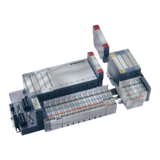
Page 17: Bl20 Components
BL20 components BL20 components For a detailed explanation of the individual BL20 components, please refer to chapter 2 and chapter 4. The “Appendix“ to this manual contains (amongst others) a list of all BL20 components and the assignment of electronics modules to base modules. -
Page 18: Power Distribution Modules
Power distribution modules The power supply for gateways and I/O modules is fed to the power distribution modules; therefore, it is not necessary to supply each individual module with a separate voltage. Figure 2-2: Power distribution module D300458 1211 - BL20 PBDP... -
Page 19: Electronics Modules
BL20 components 2.2.3 Electronics modules Electronics modules contain the functions of the BL20 modules (power distribution modules, digital and analog input/output modules, and technology modules). Electronics modules are plugged onto the base modules and are not directly connected to the wiring. -
Page 20: Base Modules
The assignment table in the Section “Ordering Information“ of the “Appendix“ shows the possible combinations of electronics and base modules. Figure 2-5: Base module with tension clamp connection Figure 2-6: Base module with screw connection Figure 2-7: Base module in block design D300458 1211 - BL20 PBDP... -
Page 21: Bl20 Economy
End plate An end plate on the right-hand side physically completes the BL20 station. An end bracket mounted into the end plate ensures that the BL20 station remains secure on the mounting rail even when subjected to vibration. Figure 2-9:... -
Page 22: End Bracket
Jumpers (QVRs) are used to bridge a connection level of a 4-wire base module. They can be used to connect potentials in relay modules (bridging the relay roots); thus considerably reducing the amount of wiring. Figure 2-11: Jumpers D300458 1211 - BL20 PBDP... -
Page 23: Shield Connection (Gateway)
2.2.10 Marking material Labels: for labeling BL20 electronics modules. Markers: for colored identification of connection levels of BL20 base modules. Dekafix connector markers: for numbering the mounting slots on BL20 base modules. Figure 2-13: Marking material D300458 1211 - BL20 PBDP... -
Page 24: 2.2.11 Shield Connection, 2-Pole For Analog Modules
2.2.11 Shield connection, 2-pole for analog modules The 2-pole shield connection can be used to connect signal-cable shielding to the base modules of analog input and output modules. A special tension-clamp operating tool (BL20-ZBW5-2) is required to mount the shield connection onto the base module. -
Page 25: Profibus-Dp
– Sync mode ............................6 – Freeze mode............................6 3.1.9 System performance ..........................6 – Data transfer between DPM1 and the DP slaves ................7 – Protective mechanisms ........................7 – Ident. number ............................ 7 3.1.10 GSD files............................... 8 D300458 1211 - BL20 PBDP... -
Page 26: System Overview
PROFIBUS-DP (Decentral Periphery) is designed for data transfer between the control and the input/ output level. TURCK BL20 stations support PROFIBUS-DP. PROFIBUS-DP is the speed-optimized PROFIBUS version, specially designed for communication between automation devices and decentralized peripheral devices. PROFIBUS-DP is suited to replace cost-intensive parallel signal transmission via digital and analogue sensors and actuators. -
Page 27: Topology
Use of Drop lines Note The length of drop lines may not exceed 6.6 m at a transmission speed of 1.5 Mbps. At a transmission speed of 12 Mbps it is not permitted to use drop lines. D300458 1211 - BL20 PBDP... -
Page 28: Transmission Rate/ Cycle Times
Note Premoulded PROFIBUS-DP cables simplify network installation, shorten set-up times and reduce wiring errors. TURCK offers an extensive and varied product spectrum for this purpose. The ordering information on the available cable types can be taken from the respective product catalogue. -
Page 29: Diagnostic Functions
Here the error cause of a single input/output bit, i.e. relating to a single channel, is indicated. Example: "Short-circuit at output 2" The PROFIBUS slaves of the BL20 series support the diagnostic functions of PROFIBUS-DP. The evaluation of the diagnostic data via the control depends on the support of the master. Note Further information on diagnostics can be taken from the device descriptions of the master interfaces of the various manufacturers. -
Page 30: Sync And Freeze Mode
Then the DPM1 changes to the "Clear" state. If this parameter is set to "False", then the DPM1 will retain its operating condition also in the event of an error and the user can determine the system response. D300458 1211 - BL20 PBDP... -
Page 31: Data Transfer Between Dpm1 And The Dp Slaves
This provides additional protection against configuration errors. The manufacturer specific ident. nos. are determined and assigned by the PROFIBUS user organization (PNO). The PNO governs the ident. nos. together with the GSD files. D300458 1211 - BL20 PBDP... -
Page 32: 3.1.10 Gsd Files
I/O data volume, transmission rates, revision status etc. This GSD file is needed to configure the station within the PROFIBUS-DP system. The GSD files can be downloaded via the TURCK website under www.turck.com. D300458 1211 - BL20 PBDP... -
Page 33: Gateways For Profibus-Dp
Technical data for BL20-GWBR-PBDP ....................10 4.2.4 Technical data for BL20-GW-PBDP-1.5MB/ BL20-GW-PBDP-1.5MB-S/ BL20-GW-PBDP-12MB and BL20-GW-PBDP-12MB-STD ............... 11 – Gateway 1.5 MBaud (BL20-GW-PBDP-1.5MB) ................11 – Gateway 12 MBaud (BL20-GW-PBDP-12MB) ................12 Fieldbus connections ........................13 4.3.1 Fieldbus connection via SUB-D female connectors................13 4.3.2... - Page 34 4.8.1 Device related diagnosis........................56 4.8.2 Device-/ identifier - and channel specific diagnosis................57 4.8.3 Description of the gateway diagnostic bits ..................58 – Module diagnosis ..........................60 – Device related diagnostic messages....................60 – Channel specific diagnostic messages ...................68 D300458 1211 - BL20 PBDP...
-
Page 35: Introduction
BL20 gateways can only be used as slaves. When the BL20 gateway has the “WAIT_PRM” status, it is not possible to check the parameters in the parameter telegram of the PROFIBUS-DP master due to the large number of module combinations and module variants. - Page 36 This gateway is an Gateway with a maximum transmission rate of 12 MBit/s, but with restricted functionality. It only supports a maximum of 4 BL20 I/O modules in block design or a maximum of 15 BL20 modules in total (including power distribution modules and planned empty slots). The connection to the PROFIBUS-DP fieldbus is made through a SUB-D connector.
-
Page 37: Connections And Switches
PS/2 socket: This is the Service interface for the connection of the gateway to the software tool I/Oassistant. The user can utilize this software to parameterize and configure the BL20 stations, and to perform diagnoses. D300458 1211 - BL20 PBDP... - Page 38 P and N leads (recommendation from the PROFIBUS user organization). The termination of a fieldbus cable type A or type B is also made only in the connector. The BL20 gateway itself has no provision for a fieldbus termination.
-
Page 39: Technical Data
Resistance to repetitive shock according to IEC 1 000 shocks, half-sinus 25 g peak value/6 ms, in 68-2-29 each case in +/- direction per space coordinate Topple and fall according to IEC 68-2-31 and free fall according to IEC 68-2-32 D300458 1211 - BL20 PBDP... - Page 40 DIN IEC 68-2-14, temperature 0 to +55 °C / 32 to 131 °F, duration 2 cycles, temperature change per minute; device in use Pollution severity according to IEC 664 (EN 61 131-2) Protection class according to IEC 529 IP20 D300458 1211 - BL20 PBDP...
-
Page 41: Structure Diagram For The Gateways
0.5 to 1.5 mm / 0.0008 to 0.0023 inch DIN 46228/1 (ferrules crimped gas-tight) 20 to 16 AWG Plug gauge according to IEC 947-1/1988 TOP connection technology Tension clamp or screw connection 4.2.2 Structure diagram for the gateways D300458 1211 - BL20 PBDP... -
Page 42: Technical Data For Bl20-Gwbr-Pbdp
Gateways for PROFIBUS-DP The BL20 gateway has the following structure: Figure 4-4: Gateway Fieldbus Service Controller External RAM Module bus structure (External) interface (Internal) External – internal ROM flash – WDG 4.2.3 Technical data for BL20-GWBR-PBDP Table 4-4: Field supply... -
Page 43: Technical Data For Bl20-Gw-Pbdp-1.5Mb/ Bl20-Gw-Pbdp-1.5Mb-S/ Bl20-Gw-Pbdp-12Mb And Bl20-Gw-Pbdp-12Mb-Std
Technical data 4.2.4 Technical data for BL20-GW-PBDP-1.5MB/ BL20-GW-PBDP-1.5MB-S/ BL20-GW-PBDP-12MB BL20-GW-PBDP-12MB-STD Table 4-5: Supply voltage General Technical Nominal value 5 V DC (distribution by the Bus Refreshing Data module) Permissible range 4.7 to 5.3 V DC Residual ripple according to EN 61 131-2... -
Page 44: Gateway 12 Mbaud (Bl20-Gw-Pbdp-12Mb)
SUB-D male connector 1.5 MBaud Transmission speed 9.6 kBit/s to 12 Mbit/s Fieldbus termination SUB-D connector Passive LWL adapters can be connected Current consumption max. 100 mA 2 hexadecimal rotary coding-switches with labeling for addressing. 4-12 D300458 1211 - BL20 PBDP... -
Page 45: Fieldbus Connections
DGND DGND Data reference potential + 5 V DC for external bus termination not assigned RxD/TxD-N Reception/transmission-data-N not assigned Note The fieldbus shielding is established via the metal hood of the male SUB-D connector. 4-13 D300458 1211 - BL20 PBDP... -
Page 46: Fieldbus Connection Via Direct Wiring (Only For 1.5 Mbaud Gateway)
When connecting to PROFIBUS-DP via direct wiring, the shield can be connected using a shield connection. The installation of the shield connection is described in chapter Note Equipotential bonding impedance ≤ 1/10 shielding impedance 4-14 D300458 1211 - BL20 PBDP... -
Page 47: Service Interface Connection
The pin assignments differ in these two options. 4.4.1 Connection using a BL20 cable BL20 cables have a PS/2 male connector (connection for female connector on gateway) and a SUB-D female connector (connection for male connector onPC). Figure 4-7: PS/2 male... -
Page 48: Connection Using Commercially Available Cables
4.4.2 Connection using commercially available cables A further possibility to connect PC and BL20 gateway is to use a commercially available connection and adapter cable. The following two cables are necessary: 1 x PS/2 cable (PS/2 male connector/PS/2 male connector) (commercially available keyboard... - Page 49 The following graphic of a PS/2 male connector / PS/2 male connector connection is a 6-wire 1:1 connection. Figure 4-12: Connection between PC and BL20 gateway using a commercially available cable A SUB-D female connector B PS/2 female con- nector <–> PS/2 male connector C PS/2 male con- nector 4-17 D300458 1211 - BL20 PBDP...
-
Page 50: Address Setting
(L = 0 to 9). The H switch is used to set L × 10 (H = 0 to 9) Note The ADDRESS switch on the BL20-GWBR-PBDP can be used to assign addresses from 1 to 99. 4-18 D300458 1211 - BL20 PBDP... - Page 51 It is not necessary to address the internal module bus. Attention If the BL20 gateway is used as the first or last station in the bus communication, then a special bus connector with a built-in or switched-in termination resistor is absolutely necessary.
-
Page 52: Setting Parameters
Setting parameters 4.6.1 Gateway parameters BL20 gateways for PROFIBUS-DP require five parameter bytes. These describe exclusively the behavior of the gateway itself. The first three parameters are defined by the PROFIBUS-DP standard. Description and allocation of gateway parameters: The texts in the columns “Parameter name“ and “Meaning“ correspond to those determined in the GSD files (Electronic Device Data Sheets), which are described in chapter 3. - Page 53 Depending on their configuration, these modules set their outputs either to “0” or to a default value, or maintain the original values. The non-configured analog output modules maintain their current output settings. 4-21 D300458 1211 - BL20 PBDP...
- Page 54 When the BL20 station is put into operation by the fieldbus master, the actual list of modules can differ slightly from the list of modules planned in the configuration software of the master: –...
-
Page 55: Module Parameters
2 bytes gateway diagnostic + 1 diagnostic bit for each connected module + active diagnostic blocks for the modules of the station which are capable for diagnostic 4.6.2 Module parameters BL20-4DI-NAMUR 4-23 D300458 1211 - BL20 PBDP... -
Page 56: Bl20-1Ai-I(0/4
The module provides the following parameter bytes per channel: Table 4-12: Assignment Parameter name Value Meaning Module parame- Byte ters BL20-1AI-I(0/ 4...20MA) A default- current mode 0...20mA settings 4...20mA value representation integer (15Bit + sign) 12Bit (left-justified) diagnostic release block BL20-2AI-I(0/4...20MA) 4-24 D300458 1211 - BL20 PBDP... -
Page 57: Bl20-1Ai-U(-10/0
The module provides the following parameter bytes per channel: Table 4-14: Assignment Parameter Value Meaning Module parame- name ters Byte BL20-1AI-U(10/ 0...+10VDC) A default- voltage mode 0...10V settings -10...+10V value representation integer (15Bit + sign) 12Bit (left-justified) diagnostic release block 4-25 D300458 1211 - BL20 PBDP... -
Page 58: Bl20-2Ai-U(-10/0
Table 4-15: Assignment Parameter Value Meaning Module parame- name ters Byte BL20-2AI-U(10/ 0...+10VDC) A default- voltage mode 0...10V settings -10...+10V value representation integer (15Bit + sign) 12Bit (left-justified) diagnostic release block channel activate deactivate 4-26 D300458 1211 - BL20 PBDP... -
Page 59: Bl20-2Ai-Pt/Ni-2/3
PT200, -200..150 °C PT500, -200..850 °C PT1000, -200..850 °C PT1000, -200..150 °C NI1000, -60..250 °C NI1000, -60..150 °C resistance, 0..100 Ω resistance, 0..200 Ω resistance, 0..400 Ω resistance, 0..1000 Ω measurement Mode Kx 2-wire 3-wire 4-27 D300458 1211 - BL20 PBDP... -
Page 60: Bl20-2Ai-Thermo-Pi
Type B, +100...1820 °C Type E, -270..1000 °C Type J, -210..1200 °C Type N, -270..1300 °C Type R, -50..1760 °C Type S, -50..1540 °C Type T, -270..400 °C +/-50 mV +/-100 mV +/-500 mV +/-1000 mV 4-28 D300458 1211 - BL20 PBDP... -
Page 61: Bl20-2Aih-I
(polling of HART-status not possible) 4…20 mA (polling of HART-status not possible) 4…20 mA HART active (cyclic polling of HART-status activated reserved 0 -1 value representation Kx integer (15 Bit + sign) NE 43 2 + 3 reserved 4-29 D300458 1211 - BL20 PBDP... - Page 62 Gateways for PROFIBUS-DP Additionally, the BL20-2AIH-I provides the following parameters for the parameterization of the HART- Variables: Table 4-19: Assignment Parameter name Value Meaning Module parame- ters BL20-2AIH-I Byte A default- Variable VA settings channel mapping VA Defines the channel of which the HART-variable is read.
-
Page 63: Bl20-4Ai-U/I
Byte ters BL20-4AI-U/I A default- 0 - 3 range x 50Hz settings 60Hz value representation integer (15Bit + sign) 12Bit (left-justified) diagnostic Kx release block channel Kx activate deactivate operation mode x voltage current 4-31 D300458 1211 - BL20 PBDP... -
Page 64: Bl20-E-8Ai-U/I-4Pt/Ni
Pt200 -200 °C ... 150 °C 3-wire Pt500 -200 °C ... 850 °C 3-wire Pt500 -200 °C ... 150 °C 3-wire Pt1000 -200 °C ... 850 °C 3-wire Pt1000 -200 °C ... 150 °C 3-wire 4-32 D300458 1211 - BL20 PBDP... - Page 65 0 ... 400 Ω resistance, 0 ... 800 Ω resistance, 0 ... 1000 Ω resistance, 0 ... 2000 Ω deactivate value representation Kx Integer (15Bit + sign) 12Bit (left-justified) diagnostics Kx release block 4-33 D300458 1211 - BL20 PBDP...
-
Page 66: Bl20-1Ao-I(0/4
12Bit (left-justified) channel Kx activate deactivate 1 - 2/ substitute value Ax The substitute value will be 4 - 5 transmitted if the respective parameters of the gateway have been set to „output substitute value“. 4-34 D300458 1211 - BL20 PBDP... -
Page 67: Bl20-2Ao-U(-10/0
12Bit (left-justified) channel Kx activate deactivate 1 - 2/ substitute value Ax The substitute value will be 4 - 5 transmitted if the respective parameters of the gateway have been set to „output substitute value“. 4-35 D300458 1211 - BL20 PBDP... -
Page 68: Bl20-E-4Ao-U/I
1/4/ parameterized substitute value channel x/ LOW Byte 7/10 2/5/ parametrparameterized substitute value channel x / HIGH Byte 8/11 4-36 D300458 1211 - BL20 PBDP... -
Page 69: Bl20-1Cnt-24Vdc
0 to + 2147483647 (2 upper count limit 0 to 32767 (Unsigned16) (HWORD) upper count limit 0 to 65535 (Unsigned16) (LWORD) hysteresis to 255 (Unsigned8) 0/ 7 pulse duration DO1, DO2 to 255 (Unsigned8) [n*2ms] 4-37 D300458 1211 - BL20 PBDP... - Page 70 2,5 μs (200kHz) sensor/input filter (A) 25 μs (20kHz) 2,5 μs (200kHz) sensor/input filter (B) 25 μs (20kHz) 2,5 μs (200kHz) sensor/input filter (DI) 25 μs (20kHz) sensor (A) normal inverted direction input (B) normal inverted 4-38 D300458 1211 - BL20 PBDP...
- Page 71 1 to 16 777 215 x 10 upper limit (HWORD) to 255 (Unsigned8) upper limit (LWORD) to 65535 8 to 9 integration time 1 to 1 000; 10 [n*10ms] 10 to 11 sensor pulse per to 65535 revolution 4-39 D300458 1211 - BL20 PBDP...
- Page 72 (A) normal inverted direction input (B) normal inverted group diagnostics release block 4 to 5 behaviour CPU/master turn off DO1 STOP proceed with operating mode DO1 switch to substitute value DO1 hold last value 4-40 D300458 1211 - BL20 PBDP...
-
Page 73: Bl20-1Rs232
User data are represented in Bytes 0 - 5. diagnostics Diagnosis activated/diagnosis deactivated: This affects the separate fieldbus-specific diagnostic message – not the diagnosis embedded in the process input data. Enable Inhibit 4-41 D300458 1211 - BL20 PBDP... - Page 74 “RTS/CTS” Hardware handshake is switched on. 0 to 7 XON character 0 – 255 XON character: This character is used to start the transmission of data from the data terminal device if the software handshake is active. 4-42 D300458 1211 - BL20 PBDP...
-
Page 75: Bl20-1Rs485/422
User data are represented in Bytes 0 - 5. diagnostics Diagnosis activated/diagnosis deactivated: This affects the separate fieldbus-specific diagnostic message – not the diagnosis embedded in the process input data. Enable Inhibit 4-43 D300458 1211 - BL20 PBDP... - Page 76 0 to 7 XOFF character 0 – 255 XOFF character: This character is used to stop the transmission of data from the data terminal device if the software handshake is active. 4-44 D300458 1211 - BL20 PBDP...
-
Page 77: Bl20-1Ssi
SSI_FRAME_LEN - INVALID_BITS_MSB- INVALID_BITS_LSB. The invalid bits at the MSB end are set to zero by masking the position value. Basically, INVALID_BITS_MSB + INVALID_BITS_LSB must be smaller than SSI_FRAME_LEN. Default: 0 = 0 4-45 D300458 1211 - BL20 PBDP... -
Page 78: Module Description In The Electronic Device Data Sheets (Gsd)
Modules cannot be unmistakably identified using this identification. Advantage: Replacement modules need not be of an identical type to be accepted by the BL20 gateway. This means that “related” modules with identical process data lengths can be used. Thus, it is possible to exchange a 2 DO 24 V DC module with 0.5A with a 2 DO 24 V DC module with 2A. -
Page 79: Example Of A Profibus-Dp Configuration
Setting parameters Module description according to type The configured module list is displayed with extended identification (special identification format), which makes an exact identification of modules possible. The BL20 gateway accepts replacement modules only of an identical type. Figure 4-15:... -
Page 80: System Description
A1, A0 data B1, B0 C1, C0 D3, D2, D1, D0 E7, E6, ... E1, E0 E15, E14, ... E9, E8 F7, F6, ... F1, F0 F15, F14, ... F9, F8 G1, G0 4-48 D300458 1211 - BL20 PBDP... -
Page 81: Parameter Configuration Data
Module bus station C: 2 DI Module bus station D: 4 DI Module bus station E: 1 AI I Module bus station F: 1 AO I Module bus station G: 2 DO 0.5 A 4-49 D300458 1211 - BL20 PBDP... - Page 82 0x01 3. manufacturer-specific byte 2. manufacturer-specific byte 1. manufacturer-specific byte IO length, consistency special identification format: I-length follows, 3 manufacturer-specific bytes to follow → (Process data: 1 byte DI for module bus station C) 4-50 D300458 1211 - BL20 PBDP...
- Page 83 0x01 3. manufacturer-specific byte 2. manufacturer-specific byte 1. manufacturer-specific byte IO length, consistency special identification format: I-length follows, 3 manufacturer-specific bytes to follow → (Process data: 2 bytes AO for module bus station F) 4-51 D300458 1211 - BL20 PBDP...
-
Page 84: Diagnostics Data
Module bus station D: No diagnostics data available Module bus station E: Bit 0: Measurement value range error Bit 1: Open circuit Module bus station F: No diagnostics data available Module bus station G: No diagnostics data available 4-52 D300458 1211 - BL20 PBDP... -
Page 85: Status Indicators/Diagnostic Messages Gateway
Status indicators/diagnostic messages gateway Status indicators/diagnostic messages gateway The gateway transmits the following diagnostics: the status of the BL20 station, the communication via the internal module bus, the communication to PROFIBUS-DP and the status of the gateway. Diagnostic messages are displayed in two ways:... - Page 86 Gateways for PROFIBUS-DP Table 4-34: Status Meaning Remedy LED indicators Module bus is not ready. – Check the individual BL20 modules for correct mounting. Red, Non-adaptable modification of the – Check the physical station for flashing, physically connected station. defective or incorrectly fitted...
-
Page 87: Diagnostic Messages Via The Software
PROFIBUS-DP master as diagnostic bytes. For the meaning of the individual diagnostic bits, please refer to the Section “Diagnostics“ in this chapter. You can find an example of diagnostic messages via a PLC in the Section Example of diagnostics with a Siemens S7-400 PLC, chapter 4-55 D300458 1211 - BL20 PBDP... -
Page 88: Diagnosis
Gateways for PROFIBUS-DP Diagnosis BL20 offers 2 possibilities for the representation of diagnostic information: device related diagnosis: diagnosis-header + 2 byte gateway-diagnosis + maximum of 61 byte module diagnosis device-/ identifier-/ channel-specific diagnosis: diagnosis-header + device related diagnosis → 2 byte gateway diagnosis + identifier related diagnosis →... -
Page 89: Device-/ Identifier - And Channel Specific Diagnosis
Bit 0 to Bit 5 contain the channel number. Bit 6 and 7 define, whether the channel is an in- or an output: 01 = input 10 = output 11 = in- and output 4-57 D300458 1211 - BL20 PBDP... -
Page 90: Description Of The Gateway Diagnostic Bits
1 = field supply U is not within the permissible range Overcurrent/ Short circuit I 0 = current I is within the permissible range 1 = current I is not within the permissible range 4-58 D300458 1211 - BL20 PBDP... - Page 91 I/O-ASSISTANT). This separates the fieldbus master from the outputs of the module bus stations. No process data exchange is taking place from the fieldbus master to the output modules. reserved Note Up to 61 bytes of module-specific diagnostic errors can follow. 4-59 D300458 1211 - BL20 PBDP...
-
Page 92: Module Diagnosis
Undervoltage field supply reserved BL20-PF-24VDC-D Table 4-37: Diagnostic Diagnostic messages BL20-PF-24VDC-D byte reserved reserved undervoltage field supply reserved BL20-PF-120/230VAC-D Table 4-38: Diagnostic Diagnostic messages BL20-PF-120/ byte 230VAC-D reserved reserved undervoltage field supply reserved 4-60 D300458 1211 - BL20 PBDP... - Page 93 4 to 20 mA n + 1 measurement value range error (channel 2) open circuit BL20-1AI-U(-10/0...+10VDC Table 4-42: Diagnostic Diagnostic messages BL20-1AI-U byte (-10/0...+10VDC measurement value range error (channel 1) 4-61 D300458 1211 - BL20 PBDP...
- Page 94 Table 4-45: Diagnostic Diagnostic messages BL20-2AI- byte THERMO-PI A threshold: measurement value range error 1% of the posi- open circuit tive measure- (only in temperature measurement ranges) ment range end value 2 to 7 reserved 4-62 D300458 1211 - BL20 PBDP...
- Page 95 + 3 open circuit tive measure- (ch. 3) ment range end 2 to 7 reserved value, under- flow diagnostic only in value range 4...20 mA B threshold: 3 mA (only in value range 4...20 mA 4-63 D300458 1211 - BL20 PBDP...
- Page 96 BL20-2DO-24VDC-0.5A-N Table 4-50: Diagnostic Diagnostic messages BL20-2DO- byte 24VDC-0.5A-N overcurrent (short-circuit channel 1) overcurrent (short-circuit channel 2) BL20-2DO-24VDC-2A-P Table 4-51: Diagnostic Diagnostic messages BL20-2DO- byte 24VDC-2A-P overcurrent (short-circuit channel 1) overcurrent (short-circuit channel 2) 4-64 D300458 1211 - BL20 PBDP...
- Page 97 Overcurrent (short-circuit channel 29-32) BL20-E-4AO-U/I Diagnostic Diagnostic messages Table 4-55: BL20-E-AO-U/I byte A Thresholds, see measurement value range error IO-manual 1 + 2 reserved D300717 overflow / underflow 4 bis 6 reserved hardware failure 4-65 D300458 1211 - BL20 PBDP...
- Page 98 Lower limit wrong Operating mode wrong Operation mode Bit = 1 measurement operation is active BL20-1RS232 Table 4-57: Diagnostic Diagnostic messages BL20-1RS232 byte parameterization error hardware failure data flow control error frame error buffer overflow 4-66 D300458 1211 - BL20 PBDP...
- Page 99 (only in RS422-mode) frame error buffer overflow BL20-1SSI Table 4-59: Diagnostic Diagnostic messages BL20-1SSI byte SSI group diagnostics open circuit sensor value overflow sensor value underflow parameterization error 4-67 D300458 1211 - BL20 PBDP...
- Page 100 2 overcurrent/ short circuit sensor 3 open circuit sensor 3 overcurrent/ short circuit sensor 4 open circuit sensor 4 BL20-xAI-I(0/4...20MA) Table 4-64: Value (dec.) Diagnostic messages BL20-xAI-I (0/4...20MA) measurement value range error open circuit 4-68 D300458 1211 - BL20 PBDP...
- Page 101 BL20-4AI-U/I Table 4-68: Value (dec.) Diagnostic messages BL20-4AI-U/I measurement value range error open circuit BL20-8AI-U/I-4PT/NI Table 4-69: Value (dec.) Diagnostic messages BL20-8AI-U/I-4PT/ measurement value range error open circuit overcurrent/short-circuit overflow/underflow Hardwarefehler 4-69 D300458 1211 - BL20 PBDP...
- Page 102 Table 4-73: Value (dec.) Diagnostic messages BL20-2DO- 24VDC-2A-P ovrcurr/shrt-circ(>=1 of K1-4) BL20-4DO-24VDC-0.5A-P Table 4-74: Value (dec.) Diagnostic messages BL20-4DO- 24VDC-0.5A-P ovrcurr/shrt-circ(>=1 of K1-4) BL20-16DO-24VDC-0.5A-P Table 4-75: Value (dec.) Diagnostic messages BL20-16DO- 24VDC-0.5A-P ovrcurr/shrt-circ(>=1 of K1-4) 4-70 D300458 1211 - BL20 PBDP...
- Page 103 (>=1 of K13-16) ovrcurr/shrt-circ (>=1 of K17-20) ovrcurr/shrt-circ (>=1 of K21-24) ovrcurr/shrt-circ (>=1 of K25-28) ovrcurr/shrt-circ (>=1 of K29-32) BL20-E-4AO-U/I Table 4-77: Value (dec.) Diagnostic messages BL20-AO-U/I measurement value range error overflow/underflow hardware failure 4-71 D300458 1211 - BL20 PBDP...
- Page 104 BL20-1RS232 Table 4-80: Value (dec.) Diagnostic messages BL20-1RS232 parameterization error hardware failure data flow control error frame error buffer overflow 4-72 D300458 1211 - BL20 PBDP...
- Page 105 (only in RS422-mode) frame error buffer overflow BL20-1SSI Table 4-82: Value (dec.) Diagnostic messages BL20-1SSI SSI group diagnostics open circuit sensor value overflow sensor value underflow parameterization error 4-73 D300458 1211 - BL20 PBDP...
- Page 106 Gateways for PROFIBUS-DP 4-74 D300458 1211 - BL20 PBDP...
-
Page 107: Connections To Automation Devices
– Reading-in the GSD files before starting the software ..............12 – Reading-in the GSD files after starting the software ............... 12 5.3.2 Selecting the BL20 gateway as a slave ....................13 5.3.3 Example of a mixed usage configuration ................... 13 5.3.4... -
Page 108: Introduction
BL20 gateways can only be used as slaves on PROFIBUS-DP. Gateways have no master function. All manufacturers of control systems offer plug-in network cards for their PLCs, to which BL20 gateways can easily be connected. Furthermore, it is possible to use a PC as a master if it has an appropriate PC PROFIBUS card. -
Page 109: Electronic Device Data Sheets (Gsd)
The device data of all BL20 modules and gateways are described in the Electronic Device Data Sheets (GSD files). These files are available for the BL20 gateway with a 1.5 Mbaud transmission rate and the BL20 gateway with a 12 Mbaud transmission rate. -
Page 110: Compressing Module Process Data
BL20 stations, as well as further functions, for example, the grouping of BL20 modules of the same type to blocks. The aim of creating these blocks is to save configuration bytes and at the same time increase the amount of parameters and process data transmitted via the internal module bus. - Page 111 Follow-up modules (module descriptions according to type or standard, identified in the GSD file by “..S-BL20...“ or “...T-BL20...“); their process data bits are added to the process data of the 1. module in the respective block, until the limit of 1 byte per process data is reached.
-
Page 112: Example Of Compressing Module Process Data
These are explained by the following example: Figure 5-4: Example of a BL20 station An overview of possible configuration options for the depicted BL20 station are shown in the following tables. The entries in the columns “Module (*)” and “Module (**)” mean: Module (*):... - Page 113 S-BL20-1AO-I(0/4...20MA) 2 DO 0.5A S-BL20-2DO-24VDC-0.5A-P 2 DO 0.5A ..S-BL20-2DO-24VDC-0.5A-P 2 DO 0.5A ..S-BL20-2DO-24VDC-0.5A-P 2 DI ..S-BL20-2DI-24VDC-P 1 AI S-BL20-1AI-U(-10/0...+10VDC) 2 DO 2A ..S-BL20-2DO-24VDC-2A-P Figure 5-5: Use of standard module description in a Siemens PLC system D300458 1211 - BL20 PBDP...
- Page 114 2 DI ..T-BL20-2DI -4VDC-P 2 DI T-BL20-2DI-24VDC-P 2 DI ..T-BL20-2DI-24VDC-P 1 AO I T-BL20-1AO-I(0/4...20MA) 2 DO 0.5A 3* T-BL20-2DO-24VDC-0.5A-P 2 DO 0.5A 2 DO 0.5A 2 DI ..T-BL20-2DI-24VDC-P 1 AI T-BL20-1AI-U(-10/0...+10VDC) 2 DO 2A T-BL20-2DO-24VDC-2A-P D300458 1211 - BL20 PBDP...
-
Page 115: General Note
1 Byte. The follow-up modules can be used in both the standard module description and in the description according to type. Note Exception: Multiple modules (“2*T-BL20...” to “4*T-BL20...”) cannot be used as follow-up modules. D300458 1211 - BL20 PBDP... -
Page 116: Standard Module Description
(4 DI) has been plugged between the two modules. Note The option of creating blocks of modules can be decisively influenced during configuration of an BL20 station. 5-10 D300458 1211 - BL20 PBDP... -
Page 117: Module Description According To Type
It should be noted, when using “multiple modules” that this option is only available for modules mounted next to each other. This means, in contrast to the agreements reached above, it is not possible to consider modules that are not mounted next to one another as blocks. 5-11 D300458 1211 - BL20 PBDP... -
Page 118: Connection To A Siemens S7 Plc
5.3.1 Reading-in the GSD file The GSD files for BL20 must be read into the software before you can begin with the initial configuration. There are two procedures possible for reading-in the files: Reading-in the GSD files before starting the software Copy the GSD files “TRCKFF0D.gsd”... -
Page 119: Selecting The Bl20 Gateway As A Slave
The exact configuration procedure can be found in the operators manual, which is supplied with the software. 5.3.2 Selecting the BL20 gateway as a slave To insert a BL20 station as a slave, select the required entry from the hardware catalog. Figure 5-9: Inserting a BL20 station 1.5 Mbaud as a slave 5.3.3... -
Page 120: Setting Gateway Parameters
5.3.4 Setting gateway parameters To set the gateway parameters, double-click the corresponding BL20 station. In the window which opens, click the “Assigning Parameters” button to open the dialog box where you can set the gateway parameters. Figure 5-11: Setting the... -
Page 121: Configuring The Bl20 Station
5.3.6 Setting parameters for BL20 modules If BL20 modules are entered whose parameters can be set, it is possible to open the dialog box with the relevant options by double-clicking the corresponding module. The parameters of the individual BL20 modules are described in chapter 4. -
Page 122: Diagnostics On Profibus-Dp
Table 5-7: Module Number of Diagnostic bytes in Diagnostic bytes diagnostic PROFIBUS-DP of the example bytes station BL20-GW-PBDP-1.5MB 7 to 9 BL20-BR-24VDC-D BL20-2DI-24VDC-P BL20-4DI-24VDC-P BL20-2DI-24VDC-P BL20-2DI-24VDC-P BL20-2DI-24VDC-P BL20-1AO-I(0/4...20MA) BL20-2DO-24VDC-0.5A-P BL20-2DO-24VDC-0.5A-P BL20-2DO-24VDC-0.5A-P BL20-2DI-24VDC-P BL20-1AI-U(-10/0...+10VDC) BL20-2DO-24VDC-2A-P 5-16 D300458 1211 - BL20 PBDP... - Page 123 The Siemens S7 PLC (PROFIBUS-DP (Master) evaluates the diagnostic information from the PROFIBUS- DP slaves with a special function block, which can be obtained directly from Siemens. 5-17 D300458 1211 - BL20 PBDP...
-
Page 124: Example Of Diagnostics With A Siemens S7-400 Plc
The software STEP 7, version 5.0.2.0 from Siemens, is used in our example to describe diagnostic messages in the PLC (S7-400). The make-up of the station corresponds to the BL20 station described in the Section “Connection to a Siemens S7 PLC“ in this chapter. - Page 125 The in grey highlighted operands correspond to the standard header of PROFIBUS-DP standards. The diagnostic bits and bytes for the gateway and the BL20 modules are descripted in chapter 2. The representation of the diagnostic messages in the table VAT1 is updated following a renewed diagnosis.
-
Page 126: Short-Circuit In A Digital Output Module
“DIA“ LED on the gateway indicated that the gateway was generating an extended diagnosis by flashing red. The LED’s “DIA“ and “11“ of the digital output module lit up red. The normal status was restored to the LED indicators by repairing the short-circuit. 5-20 D300458 1211 - BL20 PBDP... -
Page 127: Planned But Not Plugged I/O Module
Gateway diagnostic byte 1, bit 3 “Station configuration changed“ In this example, a planned BL20 module was pulled. As a result, the “IOs” LED on the gateway indicated an acceptable change to the physical constellation of the module bus station by flashing alternately red/green. - Page 128 Connections to automation devices 5-22 D300458 1211 - BL20 PBDP...
-
Page 129: Guidelines For Station Planning
Protecting the service interface on the gateway ................18 6.2.5 C-rail (cross connection)........................18 6.2.6 Direct wiring of relay modules ......................20 Plugging and pulling electronics modules ..................21 Extending an existing station ......................22 Firmware download ........................23 D300458 1211 - BL20 PBDP... -
Page 130: Module Arrangement On The Mounting Rail
6.1.3 Maximum system extension A BL20 station can consist of a gateway and a maximum of 74 modules in slice design (equivalent to 1 m in length of mounting rail including the end bracket and endplate). The limit placed on the maximum possible number of channels is based on the number of bytes of the... - Page 131 Counter BL20-1CNT-24VDC Standard compressed RS232 interface BL20-1RS232 Standard compressed RS485/422 BL20-1RS485/422 Standard interface compressed SSI interface BL20-1SSI Standard compressed plus 2 Bus Refreshing modules BL20-BR-24VDC-D plus 1 Bus Refreshing module BL20-BR-24VDC-D D300458 1211 - BL20 PBDP...
- Page 132 Analog outputs, BL20-2AO-U(-10/0...+10VDC) According to voltage type Counter 7/ 7 BL20-1CNT-24VDC Standard RS232 interface BL20-1RS232 Standard RS485/422 BL20-1RS485/422 Standard interface SSI interface BL20-1SSI Standard plus 2 Bus Refreshing modules BL20-BR-24VDC-D plus 1 Bus Refreshing module BL20-BR-24VDC-D D300458 1211 - BL20 PBDP...
- Page 133 Module arrangement on the mounting rail The following table offers an overview of the process data, diagnostic, parameter and configuration bytes of the individual BL20 modules: Overview of the process data and diagnostic bytes: Table 6-3: BL20 Module Process data bytes...
- Page 134 8 (Input)/ – 8 (Output) BL20-1RS485/422 8 (Input)/ – 8 (Output) BL20-1SSI 8 (Input)/ – 8 (Output) With compressed module description as follow-up module 2 bytes With compressed module description as follow-up module 4 bytes D300458 1211 - BL20 PBDP...
- Page 135 Gateway BL20-BR-24VDC-D – – BL20-PF-24VDC-D – – BL20-PF-120/230VAC-D – – BL20-2DI-24VDC-P BL20-2DI-24VDC-N BL20-2DI-120/230VAC BL20-4DI-24VDC-P BL20-4DI-24VDC-N BL20-16DI-24VDC-P BL20-32DI-24VDC-P BL20-1AI-I(0/4...20MA) BL20-2AI-I(0/4...20MA) BL20-1AI-U(-10/0...+10VDC) BL20-2AI-U(-10/0...+10VDC) BL20-2AI-PT/NI-2/3 BL20-2AI-THERMO-PI BL20-2DO-24VDC-2A-P BL20-2DO-24VDC-0.5A-P BL20-2DO-24VDC-0.5A-N BL20-4DO-24VDC-0.5A-P BL20-16DO-24VDC-0.5A-P BL20-1AO-I(0/4...20MA) BL20-2AO-I(0/4...20MA) BL20-2AO-U(-10/0...+10VDC) BL20-2DO-R-NC BL20-2DO-R-NO BL20-2DO-R-CO D300458 1211 - BL20 PBDP...
- Page 136 Ensure that a sufficient number of Power Feeding or Bus Refreshing modules are used if the system is extended to its maximum. Note If the system limits are exceeded, the software I/O-ASSISTANT generates an error message when the user activates the command “Station → Verify“. D300458 1211 - BL20 PBDP...
-
Page 137: Overview Of The Process Data, Diagnostic, Parameter And Configuration Bytes Based On An Example
If more than 4 modules in block design, or more than 15 modules in total are used, then the gateway (BL20-GW-PBDP-12MB-STD does not operate any module that follows the maximum allowed (from the 5th module in block design or the 16th module onwards). There is no communication with the excessive modules via the module bus. - Page 138 Gateway – – BL20-BR-24VDC-D – BL20-2DI-24VDC-P BL20-4DI-24VDC-P BL20-2DI-24VDC-P BL20-2DI-24VDC-P BL20-2DI-24VDC-P BL20-1AO-I(0/4...20MA) BL20-2DO-24VDC-0.5A-P BL20-2DO-24VDC-0.5A-P BL20-2DO-24VDC-0.5A-P BL20-2DI-24VDC-P BL20-1AI-U(-10/0...+10VDC) BL20-2DO-24VDC-2A-P Total: Not compressed module description Compressed module description Module available in not compressed module description only 6-10 D300458 1211 - BL20 PBDP...
- Page 139 Gateway BL20-BR-24VDC-D BL20-2DI-24VDC-P BL20-4DI-24VDC-P BL20-2DI-24VDC-P BL20-2DI-24VDC-P BL20-2DI-24VDC-P BL20-1AO-I(0/4...20MA) BL20-2DO-24VDC-0.5A-P BL20-2DO-24VDC-0.5A-P BL20-2DO-24VDC-0.5A-P BL20-2DI-24VDC-P BL20-1AI-U(-10/0...+10VDC) BL20-2DO-24VDC-2A-P Total: Not compressed module description Compressed module description Bus Refreshing module available in module description according to type only 6-11 D300458 1211 - BL20 PBDP...
-
Page 140: Power Supply
6.2.2 Module bus refreshing The number of BL20 modules that can be supplied by the gateway or a seperate Bus Refreshing module via the internal module bus depends on the respective nominal current consumption of the individual modules on the module bus.. - Page 141 Maximum permissible current via module bus: 1 500 mA The calculation shows that an additional/further Bus Refreshing module is required at the latest following the last BL20-2AO module. This Bus Refreshing module is sufficient to supply the remaining modules. Note The power requirements of the BL20 gateway is to be considered when calculating the required number of Bus Refreshing modules.
- Page 142 120 mA BL20-32DO-24VDC-0.5A-P 30 mA BL20-1AO-I(0/4...20MA) 39 mA BL20-2AO-I(0/4...20MA) 40 mA BL20-2AO-U(-10/0...+10VDC) 43 mA BL20-2DO-R-NC 28 mA BL20-2DO-R-NO 28 mA BL20-2DO-R-CO 28 mA BL20-1CNT-24VDC 40 mA BL20-1RS232 140 mA BL20-1RS485/422 60 mA BL20-1SSI 50 mA 6-14 D300458 1211 - BL20 PBDP...
- Page 143 Note Bus Refreshing modules which do not supply the gateway with power are to be combined with either a BL20-P3T-SBB-B or a BL20-P4T-SBBC-B (tension clamp connection) base module or with the base modules BL20-P3S-SBB-B or BL20-P4S-SBBC-B (screw connection). Figure 6-2:...
-
Page 144: Creating Potential Groups
In order to comply with radiation limit values in accordance with EN 55 011/ 2 000, the supply lines of the BL20-BR-24VDC-D module for supplying the gateway with power are to be fed through a ferrite ring (PS416-ZBX-405). This is to be placed immediately next to the connection terminals. - Page 145 When using a digital input module for 120/230 V AC, it should be ensured that a potential group is created in conjunction with the Power Feeding module BL20-PF-120/230VAC-D. Attention It is not permitted to use the modules with 24 V DC and 120/230 V AC field supply in a joint potential group.
-
Page 146: Protecting The Service Interface On The Gateway
Access to the C-rail is possible with the help of base modules with a C in their designation (for example, BL20-S4T-SBCS). The corresponding connection level is indicated on these modules by a thick black line. The black line is continuous on all I/O modules. On power distribution modules, the black line is only above the connection 24. - Page 147 C-rails can be used for a common voltage supply when relay modules are planned. To accomplish this, the load voltage is connected to a Power Feeding module with the BL20-P4x-SBBC base module with tension clamp or screw connection. All the following relay modules are then supplied with power via the C-rail.
-
Page 148: Direct Wiring Of Relay Modules
Direct wiring of relay modules As well as the options mentioned above, relay modules can be wired directly. In this case, base modules without C-rail connections should be chosen to guarantee the potential isolation to the adjoining modules. 6-20 D300458 1211 - BL20 PBDP... -
Page 149: Plugging And Pulling Electronics Modules
BL20 enables the pulling and plugging of electronics modules without having to disconnect the field wiring. The BL20 station remains in operation if an electronics module is pulled. The voltage and current supplies as well as the protective earth connections are not interrupted. -
Page 150: Extending An Existing Station
Guidelines for station planning Extending an existing station Attention Please note that extensions to the station (mounting further modules) should be carried out only when the station is in a voltage-free state. 6-22 D300458 1211 - BL20 PBDP... -
Page 151: Firmware Download
ASSISTANT. More information is available in the program’s online help. Attention The station should be disconnected from the fieldbus when downloading. Firmware must be downloaded by authorized personnel only. The field level must be isolated. 6-23 D300458 1211 - BL20 PBDP... - Page 152 Guidelines for station planning 6-24 D300458 1211 - BL20 PBDP...
-
Page 153: Guidelines For Electrical Installation
EMC compliant cabinet installation ...................... 9 7.3.5 Shielding of cables ..........................10 7.3.6 Potential compensation........................10 7.3.7 Switching inductive loads........................12 7.3.8 Protection against electrostatic discharge (ESD) ................12 Bus connection..........................13 – Wiring............................... 13 Two-pole shield connection ......................14 D300458 1211 - BL20 PBDP... -
Page 154: General Notes
The cable duct joints must be electrically connected and the cable ducts must be earthed. Danger Observe all valid guidelines concerning internal and external lightning protection and grounding specifications when routing cables outside of buildings. D300458 1211 - BL20 PBDP... -
Page 155: Lightning Protection
The adherence to these parameters becomes more important the higher the baud rate, the more stations there are on the bus and the longer the length of the cable. Figure 7-1: Shield inside: Representation of Twisted cable pair a PROFIBUS-DP cable terminating resistor Station 0 Station 31 D300458 1211 - BL20 PBDP... -
Page 156: Cable Types
Guidelines for electrical installation 7.1.4 Cable types Turck offers a variety of cable types for fieldbus lines as premoulded or bulk cables with different connectors. The ordering information for the available cable types can be found in the TURCK BL20 catalogs. -
Page 157: Potential Relationships
Potential relationships 7.2.1 General The potential relationship of a PROFIBUS-DP system realized with BL20 modules is characterized by the following: The system’s power supply to the gateway, I/O modules and the field level is distributed via a Bus Refreshing module. -
Page 158: Non-Isolated Installation
In a non-isolated installation, the reference potentials of the control and load circuitry are galvanically connected. Figure 7-4: Non-isolated system and field supply Gateway I/O module I/O module I/O module BR module PF module C-rail external D300458 1211 - BL20 PBDP... -
Page 159: Electromagnetic Compatibility (Emc)
7.3.1 Ensuring electromagnetic compatibility The EMC of BL20 modules is guaranteed when the following basic rules are adhered to: Correct and large surface grounding of inactive metal components. Correct shielding of cables and devices. Proper cable routing – correct wiring. -
Page 160: Mounting Rails
Remove the isolating layer from all painted, anodized or isolated metal components at the connection point. Protect the connection point against corrosion (for example with grease; caution: use only suitable grease). D300458 1211 - BL20 PBDP... -
Page 161: Emc Compliant Cabinet Installation
The protective conductor terminal block must be connected to the protective conductor rail. 5 Protective conductor system cable (grounding point) The cable must be connected over a large surface area with the protective conductor system. D300458 1211 - BL20 PBDP... -
Page 162: Shielding Of Cables
A potential-compensation cable must be routed to the potential compensation. Danger Never use the shield as a potential compensation. 7-10 D300458 1211 - BL20 PBDP... -
Page 163: Potential Compensation
Compensation cables and data cables should be routed as close together as possible, meaning the enclosed area should be kept as small as possible. Figure 7-8: Potential compensation between switchgear cabinets Potential compensation 7-11 D300458 1211 - BL20 PBDP... -
Page 164: Switching Inductive Loads
Protection against electrostatic discharge (ESD) Attention Electronics modules and base modules are at risk from electrostatic discharge when disassembled. Avoid touching the bus connections with bare fingers as this can lead to ESD damage. 7-12 D300458 1211 - BL20 PBDP... -
Page 165: Bus Connection
Bus connection Bus connection The bus connection of BL20 I/O modules is established via a 9-pole SUB-D connector according to RS 485 DIN 19 245 Part 1 or via direct wiring with a tension clamp terminal on the gateway. The assignment of the connections is described fully in chapter 2. - Page 166 Guidelines for electrical installation Attention The two signal wires must not be reversed! 7-14 D300458 1211 - BL20 PBDP...
-
Page 167: Two-Pole Shield Connection
Two-pole shield connection Shielded cables can be used for analog input and output signals. The connection between the shield and the respective base module can be made via a shield connection (BL20-ZBW2), which is available as an accessory. Figure 7-11:... - Page 168 Guidelines for electrical installation 7-16 D300458 1211 - BL20 PBDP...
-
Page 169: Integration Of Technology Modules In Profibus-Dp
8.2.1 Data Image ............................36 – Process input data (PDin) ........................ 36 – Process output data (PDout) ......................38 Integration of the RS485/422 module BL20-1RS485/422 ............... 40 8.3.1 Data Image ............................40 – Process input data (PDin) ........................ 40 – Process output data (PDout) ......................42 Integration of the SSI module BL20-1SSI .................. -
Page 170: Integration Of The Counter Module Bl20-1Cnt-24Vdc
8.1.1 Count mode: data image Process output data The process output data is the data that is output from the PLC via the gateway to the BL20-1CNT- 24VDC module. The BL20 module allows some parameters to be modified during operation. - Page 171 Integration of the counter module BL20-1CNT-24VDC Structure of the data bytes in PROFIBUS-DP with “Function and behaviour of DO1/DO2“: Table 8-2: PDOut with Byte “Function and behaviour of DO1/DO2“ X = reserved LOAD_ LOAD_CM LOAD_CM LOAD_ LOAD_ PREPARE PARAM VAL2...
- Page 172 DO2 output “0“ → “1“: DO1 and DO2 can indicate the status of data bit SET_DO1 and DO_PARAM SET_DO2 or comparison results. The latest telegram (MODE_DO1 and MODE_DO2) indicates the function required for DO1 and DO2. D300458 1211 - BL20 PBDP...
-
Page 173: Process Input Data
“0“ → “1“: The value in bytes 0 to 3 is accepted directly as the new count value. Process input data Process input data is data from the connected field device that is transmitted via the BL20-1CNT-24VDC module to the PLC. This is transferred in an 8-byte format as follows: 2 bytes contain status information. - Page 174 Values above the upper count limit or below the lower count limit were selected for Load value direct or Load value in preparation. STS_LOAD Status of load function Set if the Load function is running. STS_DN 1: Status direction down. D300458 1211 - BL20 PBDP...
- Page 175 Integration of the counter module BL20-1CNT-24VDC Table 8-5: Bits Explanations Meaning of the data bits (process input) STS_UP 1: Status direction up. STS_DO2 The DO2 status bit indicates the status of digital output DO2. STS_DO1 The DO1 status bit indicates the status of digital output DO1.
-
Page 176: Parameters For Count Mode
Byte 15 (0/1) The list parameters are set by means of a fieldbus configuration tool or the I/Oassistant software package. Some parameters cannot be modified online. These parameters must be defined before D300458 1211 - BL20 PBDP... - Page 177 Integration of the counter module BL20-1CNT-24VDC commissioning. Some parameters can also be modified via the process output after commissioning → Process output data. Note The current count operation is stopped if parameters are changed during operation. Table 8-7: Designation Description...
- Page 178 CPU/master stop = 10 – diagnostic DO1 The Short-/open circuit DO diagnostic message is not blocked. The Short-/open circuit DO diagnostic message is blocked. – hysteresis 0 to 255 (UINT) – Pulse duration DO1, DO2 [n*2ms] 8-10 D300458 1211 - BL20 PBDP...
- Page 179 Integration of the counter module BL20-1CNT-24VDC Table 8-7: Designation Description Parameters for Value count modes A Default value 0 to 255 (UINT) – count mode 000000 continuous count 000001 single-action count 000010 periodical count 000011 Reserve 011111 – gate function...
- Page 180 – upper count limit (HWORD) 0 to 0 to 32767 see above: „lower count limit“ 7FFF (SINT) FFFF – upper count limit (LWORD) 0 to 0 to 655351 see above: „lower count limit“ 7FFF (SINT) FFFF 8-12 D300458 1211 - BL20 PBDP...
-
Page 181: Diagnostics For Count Mode
Integration of the counter module BL20-1CNT-24VDC Diagnostics for count mode The parameter setting for the PROFIBUS-DP gateway provides the Gateway Diagnostics parameter for selecting between two different diagnostics displays. Choose “Devices, ID, Channel Diagnostics” to select more detailed diagnostics indication. The diagnostics message will then consist of the following... - Page 182 This message is always shown in conjunction with other diagnostics messages and indicates that measurement mode is active. This message never occurs in count mode. Note Counting should not be started if there is a parameter error (diagnostics bits 2 to 6)! 8-14 D300458 1211 - BL20 PBDP...
-
Page 183: Measurement Mode: Data Image
Measurement mode: data image Process output for measurement mode The process output data is the data that is output from the PLC via the gateway to the BL20-1CNT- 24VDC module. The BL20-1CNT-24VDC module allows some parameters to be modified during operation. - Page 184 Structure of the data bytes in PROFIBUS-DP with „Integration time set“: Table 8-11: Structure of the Byte data bytes with „Integration time set“ X = reserved LOAD_ LOAD_ LOAD_ LOAD_ INTTIME UPLIMIT LOLIMIT PARAM EXTF_ CTRL_ SET_ RES_ GATE Integration time 8-16 D300458 1211 - BL20 PBDP...
- Page 185 Integration of the counter module BL20-1CNT-24VDC Table 8-12: Control bit Explanations Meaning of the data bits (process output) EXTF_ ACK Error acknowledgement The ERR_DO or ERR_24Vdc error bits must be acknowledged with the control bit EXTF_ACK after the cause of the fault has been rectified. This control bit must then be reset again.
- Page 186 STS_OFLW = 1 or STS_UFLW = 1 (process input). – 10: Output DO1 indicates a value below the lower measuring limit. STS_UFLW = 1 (process input) – 11:Output DO1 indicates a value above the upper measuring limit. STS_OFLW = 1 (process input) 8-18 D300458 1211 - BL20 PBDP...
-
Page 187: Process Input For Measurement Mode
Integration of the counter module BL20-1CNT-24VDC Process input for measurement mode Process input data is data from the connected field device that is transmitted via the XN-1CNT-24VDC module to the PLC. This is transferred in an 8-byte format as follows: 2 bytes contain status information. - Page 188 The measured value is updated with every elapsed time interval. The end of a measurement (expiry of the time interval) is indicated with the status bit STS_CMP1. The bit must be reset with RES_STS: 0 → 1. 8-20 D300458 1211 - BL20 PBDP...
- Page 189 Integration of the counter module BL20-1CNT-24VDC Parameters for measurement mode Parameters consist of data that has to be sent to the module so that it can operate correctly in the application concerned. Some parameters refer to the physical inputs/outputs A, B, DI, DO.
- Page 190 – 1 to f 0 to 255 – 1 to n – 1 to t – upper limit (LWORD) 65 535 0 to 65 535 – integration time [n*10 ms]:“ or number of periods 8-22 D300458 1211 - BL20 PBDP...
-
Page 191: Parameters For Measurement Mode
The process entry/check-back interface returns the status rotation direction via STS_DN and STS_UP. rotary sensor: The evaluation options can be set in the BL20 counter module single configuration. The following settings are possible: – Single – Double – Fourfold... - Page 192 A failure of the higher-level PLC causes output DO1 to assume the substitute value value specified at Substitute value DO1. DO1 hold last A failure of the higher-level PLC causes output DO1 to retain the value status in the event of a failure 8-24 D300458 1211 - BL20 PBDP...
-
Page 193: Diagnostics For Measurement Mode
Integration of the counter module BL20-1CNT-24VDC Diagnostics for measurement mode The parameter setting for the PROFIBUS-DP gateway provides the Gateway Diagnostics parameter for selecting between two different diagnostics displays. Choose “Devices, ID, Channel Diagnostics” to select more detailed diagnostics indication. The diagnostics message will then consist of the following... - Page 194 100000 → Frequency measurement 100001 → Revolutions measurement 100010 → Period duration measurement measurement mode This message is always shown in conjunction with other diagnostics messages and indicates that messages refer to an active measurement mode. 8-26 D300458 1211 - BL20 PBDP...
-
Page 195: Guide To Setting The High And Low Words
Integration of the counter module BL20-1CNT-24VDC 8.1.3 Guide to setting the high and low words Setting the lower and upper limit The lower count limit is divided as follows (range: -2 147 483 648 (-231) to 0) in a High and a Low word: Convert your decimal count limit to hexadecimal format. - Page 196 If bit 15 is set, the reciprocal value is formed. This procedure is described in the following for the High word. The same principle applies to the High word: If bit 15 is not set, the High word is converted to the correponding positive decimal value. 8-28 D300458 1211 - BL20 PBDP...
- Page 197 High word (hexadecimal): FFFE High word (binary): 1111 1111 1111 1110 High word (decimal): -2 The calculated values are entered in the appropriate entry lines of the parameter mask for the BL20 counter module (count mode). Figure 8-1: Entering the lower...
- Page 198 High word (hexadecimal): 00BC High word (binary): 0000 0000 1011 1100 High word (decimal): 188 The calculated values are entered in the appropriate entry lines of the parameter mask for the BL20 counter module (count mode). 8-30 D300458 1211 - BL20 PBDP...
-
Page 199: Setting The Lower And Upper Measuring Limits
Integration of the counter module BL20-1CNT-24VDC Figure 8-2: Entering the upper count limit as a High and Low word (dez.) 8.1.4 Setting the lower and upper measuring limits The lower measuring limit is divided as follows into a High and a Low word: Convert your decimal measuring limit to hexadecimal format. - Page 200 1 = 32768 Low word (decimal): 64 497 The same principle applies to the High word: In the example: High word (hexadecimal): 0009 High word (binary): 0000 0000 0000 1001 High word (decimal): 9 8-32 D300458 1211 - BL20 PBDP...
- Page 201 Integration of the counter module BL20-1CNT-24VDC The calculated values are entered in the appropriate entry lines of the parameter mask for the BL20 counter module (measurement mode). Figure 8-3: Entering the lower measuring limit as a High and Low word (dez.) The upper measuring limit is divided as follows into a High and a Low word: Convert your decimal measuring limit to hexadecimal format.
- Page 202 1 = 32768 Low word (decimal): 62 059 The same principle applies to the High word: In the example: High word (hexadecimal): 000B High word (binary): 0000 0000 0000 1011 High word (decimal): 11 8-34 D300458 1211 - BL20 PBDP...
- Page 203 Integration of the counter module BL20-1CNT-24VDC The calculated values are entered in the appropriate entry lines of the parameter mask for the BL20 counter module (measurement mode). Figure 8-4: Entering the upper measuring limit as a High and Low word...
-
Page 204: Integration Of The Rs232 Module Bl20-1Rs232
Data Image Process input data (PDin) The incoming data are stored in the receive-buffer of the BL20-1RS232 module, segmented and transferred to the PLC via the module bus and the gateway. The transmission is realized in a 8-byte format, structured as follows:... - Page 205 Integration of the RS232 module BL20-1RS232 Table 8-18: Designation Value Meaning Meaning of the BufOvfl; FrameErr; 0 - 255 Diagnostic information (correspond to the diagnostic information data bits HndShErr; in the diagnosis telegram). (process input) HwFailure; PrmErr These diagnostics are always displayed and independent to the setting of the parameter „Diagnostics“.
- Page 206 Integration of Technology Modules in PROFIBUS-DP Process output data (PDout) Process output data are data which are sent from the PLC via the gateway and the BL20-1RS232 module to a connected field device. The data received from the PLC are loaded into the transmit- buffer in the BL20-1RS232 module.
- Page 207 Integration of the RS232 module BL20-1RS232 Table 8-19: Designation Value Meaning Meaning of the RXBUF FLUSH 0 - 1 This bit is used to flush the receive-buffer. data bits If STATRES = 1: (process output) The command RXBUF FLUSH = 1 is ignored.
-
Page 208: Integration Of The Rs485/422 Module Bl20-1Rs485/422
Data Image Process input data (PDin) The incoming data are stored in the receive-buffer of the BL20-1RS485/422 module, segmented and transferred to the PLC via the module bus and the gateway. The transmission is realized in a 8-byte format, structured as follows:... - Page 209 Integration of the RS485/422 module BL20-1RS485/422 Table 8-20: Designation Value Meaning Meaning of the BufOvfl; FrameErr; 0 - 255 Diagnostic information (correspond to the diagnostic information data bits HndShErr; HwFailure; in the diagnosis telegram). (process input) PrmErr These diagnostics are always displayed and independent to the setting of the parameter „Diagnostics“.
- Page 210 Integration of Technology Modules in PROFIBUS-DP Process output data (PDout) Process output data are data which are sent from the PLC via the gateway and the BL20-1RS485/422 module to a connected field device. The data received from the PLC are loaded into the transmit- buffer in the BL20-1RS485/422 module.
- Page 211 Integration of the RS485/422 module BL20-1RS485/422 Table 8-21: Designation Value Meaning Meaning of the RXBUF FLUSH 0 - 1 This bit is used to flush the receive-buffer. data bits If STATRES = 1: (process output) The command RXBUF FLUSH = 1 is ignored.
-
Page 212: Integration Of The Ssi Module Bl20-1Ssi
The field input data is transferred from the connected field device to the BL20-1SSI module. The process input data is the data that is transferred to the PLC from the BL20-1SS1 via a gateway. This is transferred in an 8 byte format as follows: 4 bytes are used for representing the data that was read from the register with the address stated at REG_RD_ADR. - Page 213 Integration of the SSI module BL20-1SSI Figure 8-9: Process input data Table 8-22: Designation Value Meaning Meaning of the data bits (process input) REG_RD_DATA 0... 2 Content of the register to be read if REG_RD_ABORT = 0. If REG_RD_ABORT = 1, then REG_RD_DATA = 0.
- Page 214 (REG_CMP2). This marker must be reset with CLR_CMP2 = 1 in the process output data. STS_CMP2 A comparison of the register contents has produced the following result: (REG_SSI_POS) ≠ (REG_CMP2) A comparison of the register contents has produced the following result: (REG_ SSI_POS) = (REG_CMP2) 8-46 D300458 1211 - BL20 PBDP...
- Page 215 Integration of the SSI module BL20-1SSI Table 8-22: Designation Value Meaning Meaning of the data bits (process input) REL_CMP1 A comparison of the register contents has produced the following result: (REG_SSI_POS) < (REG_CMP1) A comparison of the register contents has produced the following result: (REG_ SSI_POS) ≥...
- Page 216 The field output data is transferred from the BL20-1SSI module to the connected field device. The process output data is the data that is output from the PLC to the BL20-1SSI module via a gateway. This is transferred in an 8 byte format as follows: 4 bytes are used for representing the data that is to be written to the register with the address specified at REG_WR_DATA.
- Page 217 Integration of the SSI module BL20-1SSI Table 8-23: Designation Value Meaning Meaning of the data bits (process output) CLR_CMP2 Default status, i.e. no reset of FLAG_CMP2 active. Reset of FLAG_CMP2 active EN_CMP2 Default status, i.e. the data bits REL_CMP2, STS_CMP2 and FLAG_CMP2 always have the value 0, irrespective of the actual SSI encoder value.
-
Page 218: Integration Of The Swire Module Bl20-E-1Swire
The field input data is transferred from the connected SWIRE bus to the BL20-E-1SWIRE. The process input data is the data that is transferred by the BL20-E-1SWIRE module via a gateway to the PLC. The transfer is carried out in 8-byte format. 4 bits are reserved for each SWIRE slave. - Page 219 Integration of the SWIRE Module BL20-E-1SWIRE Process input data of SWIRE-DIL slaves The following information can be transferred for SWIRE-DIL slaves (manufacturer: Moeller): Contactor coil on/off Motor-protective circuit-breaker off (tripped) / on Status of the slave (online / diagnostics) Meaning of the 4-bit process input data on an SWIRE-DIL device:...
- Page 220 Process output Field output data is output from an BL20-E-1SWIRE to a field device. The process output data is the data that is transferred by the PLC via a gateway and the BL20-E-1SWIRE to the SWIRE slaves. The transfer is carried out in 8-byte format.
- Page 221 Integration of the SWIRE Module BL20-E-1SWIRE Diagnostics Diagnostics data contains the error messages for the higher-level system that are related to operation and application. The diagnostics indication mode for the PROFIBUS-DP gateway can be set in two ways with the “Gateway diagnostics”...
- Page 222 Integration of Technology Modules in PROFIBUS-DP This should be interpreted as follows for the BL20-E-1SWIRE modules: Table 8-29: Bit 7 Bit 6 Bit 5 Bit 4 Bit 3 Bit 2 Bit 1 Bit 0 SWIRE diagnostics Byte 1 GENERAL free...
- Page 223 (SW LED flashing). PLC SLAVE This bit indicates an error if the configuration stored in the BL20-E-1SWIRE does not match the SET configuration stored in the PLC. No error present. The SWIRE bus is ready for data exchange.
- Page 224 PLC configuration check detects differing slave numbers, types or position of an SWIRE slave. The PLC configuration check was positive (the configuration stored in the BL20-E-1SWIRE matches the SET configuration stored in the PLC) or the diagnostics function is deactivated via the parameter setting.
- Page 225 Integration of the SWIRE Module BL20-E-1SWIRE Tabelle 3: DesignationValue Meaning Meaning of diag- nostics data bits Byte 3,4 TYPE Device configuration, slave x Info field for the individual indication of a configuration error as error message. If the parameter is set with individual diagnostics, the error is indicated in this bit field...
- Page 226 Automatic SWIRE configuration If the physical structure of the SWIRE bus does not match the configuration stored in the BL20-E-1SWIRE on power up (SW LED flashing), the physical structure of the SWIRE bus must be stored in the BL20-E-1SWIRE. 0 = Inactive...
- Page 227 A default setting Configuration PLC configuration check If the PLC configuration check is activated, the configuration stored in the BL20-E- 1SWIRE is compared with the SET configuration stored in the PLC. Active The configuration stored in BL20-E-1SWIRE is compared with the SET configuration stored in the PLC.
- Page 228 AUXERR AUXERR as the power supply goes below a level at which the function of the relays is not guaranteed. Active Error message U activated AUXERR Inactive Error message U not activated AUXERR 8-60 D300458 1211 - BL20 PBDP...
- Page 229 Integration of the SWIRE Module BL20-E-1SWIRE Table 8-31: Designation Status Meaning of the parameter bits A default setting Byte 3 reserved Reserved Byte 4 reserved Was up to version VN 01-03: Lifeguarding time of the SWIRE slaves. (lifeguarding Lifeguarding time of the SWIRE slaves...
- Page 230 Integration of Technology Modules in PROFIBUS-DP 8-62 D300458 1211 - BL20 PBDP...
-
Page 231: Bl20-Approvals For Zone 2/ Division
BL20-Approvals for Zone 2/ Division 2 Note The Zone 2 - approval certificates for BL20 can be found in a separate manual for approvals D301255 on www.turck.de. D300458 1211 - BL20 PBDP... - Page 232 BL20-Approvals for Zone 2/ Division 2 D300458 1211 - BL20 PBDP...
-
Page 233: 10 Apendix
– Transmit function block FBSENDRSxxx ................... 2 – Receive function block FBRECVRSxxx..................... 4 – Transmit and receive function block FBSRRSxxx................7 10.1.2 Function block for BL20-1SSI ......................10 – Input variables ..........................11 10.2 Parameter gateway – assignment in hexadecimal format.............. 14 10.2.1... -
Page 234: Function Blocks For S7
10.1.1 Function blocks for BL20-1RSxxx The function blocks FBSENDRSxxx, FBRECVRSxxx and FBSRRSxxx control the data transfer between the PLC and the BL20-1RSxxx module. The transmission is realized in 8 byte format, 2 bytes contain control data and 6 bytes contain user data. - Page 235 The decimal number 258 has to be transmitted as the hexadecimal code W#16#102. SendData Start address for storing the transmit-data. (inputs, outputs, flags, data blocks etc.). Max_Bytes Maximum number of bytes that have to be sent (max. 65536 bytes). 10-3 D300458 1211 - BL20 PBDP...
- Page 236 – 8302h → variable error: wrong length of parameter „SendData“ RETVALSFC14 see Siemens software manual RETVALSFC15 see Siemens software manual Receive function block FBRECVRSxxx The software block FBRECVRSxxx is a handling block only used to receive data from the BL20-1RS232 module. Figure 10-2: Receive function FBRECVRSXXX block...
- Page 237 The decimal number 258 has to be transmitted as the hexadecimal code W#16#102. RecvData Start address for storing the receive-data. (inputs, outputs, flags, data blocks etc.). Max_Bytes Maximum number of bytes that have to be received (max. 65536 bytes). 10-5 D300458 1211 - BL20 PBDP...
- Page 238 – 8300h → variable error: wrong parameter „RecData“ – 8301h → variable error: wrong data type of parameter „RecData“ – 8302h → variable error: wrong length of parameter „RecData“ RETVALSFC14 see Siemens software manual RETVALSFC15 see Siemens software manual 10-6 D300458 1211 - BL20 PBDP...
- Page 239 BusyRecv BOOL BOOL EnableRecv WORD BOOL EnableSend RecvDataCnt BOOL BusySend BOOL Quit SendDataCnt WORD BOOL CLRBuf_Recv CLRBuf_Send RETVAL WORD BOOL RxD_K1 RETVALSFC14 WORD WORD WORD TxD_K1 RETVALSFC15 WORD Recv_Data MaxRecvData WORD SendData MaxSendByte WORD 10-7 D300458 1211 - BL20 PBDP...
- Page 240 Maximum number of bytes that have to be received (max. 65536 bytes). SendData Start address for storing the transmit-data. (inputs, outputs, flags, data blocks etc.). MaxSendBytes Maximum number of bytes that have to be sent (max. 65536 bytes). 10-8 D300458 1211 - BL20 PBDP...
- Page 241 – 8200h → variable error: wrong parameter „SendData“ – 8201h → variable error: wrong data type of parameter „SendData“ – 8202h → variable error: wrong length of parameter „SendData“ RETVALSFC14 see Siemens software manual RETVALSFC15 see Siemens software manual 10-9 D300458 1211 - BL20 PBDP...
-
Page 242: 10.1.2 Function Block For Bl20-1Ssi
10.1.2 Function block for BL20-1SSI The function block that was created for the SIMATIC S7 PLC system (Siemens) enables the data bytes to be exchanged between the PLC and the BL20-1SSI module, and provides in particular access to the register interface. - Page 243 Meaning Input variables of SSI_INPUT Start address for the 8-byte input address range of the BL20-1SSI module. The FB_SSI SIMATIC STEP 7 software assigns the address ranges to the appropriate modules. The address ranges are selected and displayed in the hardware configurator of the software.
- Page 244 1: A comparison of the register contents has produced the following result: (REG_SSI_POS) ≥ (REG_CMP2) STS_DN 0: The SSI encoder values are incremented or the SSI encoder values are constant. 1: The SSI encoder values are decremented. 10-12 D300458 1211 - BL20 PBDP...
- Page 245 Return value of the function (status or error code) 0: Everything OK. No error 8xxxh: Error Formal operands RETVALSFC14 See manual “System software for S7-300/400, SFC14” RETVALSFC15 See manual “System software for S7-300/400, SFC15” 10-13 D300458 1211 - BL20 PBDP...
-
Page 246: Parameter Gateway - Assignment In Hexadecimal Format
Apendix 10.2 Parameter gateway – assignment in hexadecimal format 10-14 D300458 1211 - BL20 PBDP... -
Page 247: Parameter 4
Parameter gateway – assignment in hexadecimal format 10.2.1 Parameter 4 Table 10-9: Outputs module exchange Parameter 4 Outputs module exchange A Default- settings 10-15 D300458 1211 - BL20 PBDP... - Page 248 Apendix Table 10-10: Outputs module exchange error Parameter 4 Outputs module exchange error A Default- settings 10-16 D300458 1211 - BL20 PBDP...
- Page 249 Parameter gateway – assignment in hexadecimal format Table 10-11: Outputs fieldbus error Parameter 4 Outputs fieldbus error A Default- settings 10-17 D300458 1211 - BL20 PBDP...
-
Page 250: Parameter 5
Apendix 10.2.2 Parameter 5 Table 10-12: Integer Data format Parameter 5 Integer Data format A Default- settings 10-18 D300458 1211 - BL20 PBDP... - Page 251 Parameter gateway – assignment in hexadecimal format Table 10-13: Diagnostics all Modules Parameter 5 Diagnostics all Modules A Default- settings 10-19 D300458 1211 - BL20 PBDP...
- Page 252 Apendix Table 10-14: Station configuration Parameter 5 Station configura- tion A Default- settings 10-20 D300458 1211 - BL20 PBDP...
- Page 253 Parameter gateway – assignment in hexadecimal format Table 10-15: I/Oassistant Force-Mode Parameter 5 I/Oassistant Force- Mode A Default- settings 10-21 D300458 1211 - BL20 PBDP...
- Page 254 Apendix Table 10-16: Gateway Diagnostics Parameter 5 Integer Data format A Default- settings 10-22 D300458 1211 - BL20 PBDP...
-
Page 255: Conversion Table Decimal To Hexadecimal
Conversion table decimal to hexadecimal 10.3 Conversion table decimal to hexadecimal Table 10-17: dec. hex. dec. hex. dec. hex. dec. hex. Decimal - hexadecimal 10-23 D300458 1211 - BL20 PBDP... -
Page 256: Bl20 Accessories
10.4 BL20 accessories Labels (for labeling electronics modules): BL20-LABEL/SCHEIBE (DIN A5 sheets, slice, perforated (laser printer) 5 x 57 labels) BL20-LABEL/BLOCK (DIN A5 sheets, block, perforated (laser printer) 5 x 6 labels) Markers for labeling base modules: Color markers for clear identification of the connection level on the base module (strip of 6):... - Page 257 SW-I/OASSISTANT I/Oassistant CD-ROM I/O-ASSISTANT-KABEL-BL20/BL67 I/Oassistant package Mechanical accessories BL20-ABPL End plate (mechanical termination of the BL20 station on the right-hand side) BL20-WEW-35/2-SW End bracket, black (mechanical fixing of the BL20 station) Electrical accessories BL20-SCH-1 Shield connection for direct wiring of BL20 gateway...
- Page 258 Apendix 10-26 D300458 1211 - BL20 PBDP...
-
Page 259: 11 Glossary
All units which communicate with one another via a bus. Capacitive coupling Electrical capacitive couplings occur between cables with different potentials. Typical sources of interference are, for example, parallel-routed signal cables, contactors and electrostatic discharges. 11-1 D300458 1211 - BL20 PBDP... - Page 260 In neutral grounding devices, the potential is not necessarily zero, and one speaks of the ground refe- rence. Ground connection One or more components that have a good and direct contact to earth. 11-2 D300458 1211 - BL20 PBDP...
- Page 261 All measures taken to protect a system from damage due to overvoltages caused by lightning strike. Low impedance connection Connection with a low AC impedance. Least Significant Bit Mass All interconnected inactive components that do not take on a dangerous touch potential in the case of a fault. 11-3 D300458 1211 - BL20 PBDP...
- Page 262 Mode of operation in which a station acting as a master controls the communication between other stations in a bus system. Module bus The module bus is the internal bus in a BL20 station. The BL20 modules communicate with the gateway via the module bus which is independent of the fieldbus. Most Significant Bit Multi-master mode Operating mode in which all stations in a system communicate with equal rights via the bus.
- Page 263 Setting parameters of individual stations on the bus and their modules in the configuration software of the mas- ter. Shield Conductive screen of cables, enclosures and cabinets. Shielding Description of all measures and devices used to join installation components to the shield. 11-5 D300458 1211 - BL20 PBDP...
- Page 264 Geometrical structure of a network or the circuitry arrangement. UART Universal Asynchronous Receiver/Transmitter. UART is a logic circuit which is used to convert an asynchronous serial data sequence to a parallel bit sequence or vice versa. Unidirectional Working in one direction. 11-6 D300458 1211 - BL20 PBDP...
-
Page 265: Index
............7-3 transmission rate, PROFIBUS-DP ........3-4 installation –non-isolated ..............7-6 use, prescribed ..............1-4 jumper ................2-8 Zone 2 ................9-1 labels ................2-9 lightning protection ............7-3 markers ................2-9 D300458 1211 - BL20 PBDP 12-1... - Page 266 Index 12-2 D300458 1211 - BL20 PBDP...
- Page 267 Hans Turck GmbH & Co. KG 45472 Mülheim an der Ruhr Germany Witzlebenstraße 7 Tel. +49 (0) 208 4952-0 Fax +49 (0) 208 4952-264 E-Mail more@turck.com Internet www.turck.com...
Need help?
Do you have a question about the bl20 and is the answer not in the manual?
Questions and answers