turck ECO-GATEWAY BL20 User Manual
For canopen
Hide thumbs
Also See for ECO-GATEWAY BL20:
- Instructions for use manual (537 pages) ,
- User manual (461 pages) ,
- Manual (175 pages)
Table of Contents
Advertisement
Quick Links
Advertisement
Table of Contents

Related Manuals for turck ECO-GATEWAY BL20


Summary of Contents for turck ECO-GATEWAY BL20
- Page 1 BL20 – USER MANUAL ECO-GATEWAY CANopen...
- Page 2 No part of this manual may be reproduced in any form (printed, photocopy, microfilm or any other process) or processed, duplicated or distributed by means of electronic systems without written permission of Hans Turck GmbH & Co. KG, Muelheim an der Ruhr. Subject to alterations without notice...
- Page 3 Before commencing the installation Disconnect the power supply of the device. Ensure that devices cannot be accidentally restarted. Verify isolation from the supply. Earth and short circuit. Cover or enclose neighboring units that are live. Follow the engineering instructions of the device concerned. Only suitably qualified personnel in accordance with EN 50 110-1/-2 (VDE 0 105 Part 100) may work on this device/system.
-
Page 5: Table Of Contents
Table of Contents About this Manual Documentation Concept..........................1-2 Overview ................................1-3 1.2.1 Prescribed Use......................................1-3 1.2.2 Notes Concerning Planning /Installation of this Product ......................1-3 Description of Symbols Used..........................1-4 List of revisions ..............................1-5 BL20 Philosophy The Basic Concept............................2-2 BL20 Components ............................2-3 2.2.1 Gateways ........................................2-3 2.2.2 Power Distribution Modules ................................2-5 2.2.3... - Page 6 Setting the Node-ID ............................4-10 Setting the Bit Rate ............................4-11 Activating the Bus Terminating Resistor ....................4-12 Acceptance of the BL20 Station Configuration ..................4-13 Status Indicators/ Diagnostic Messages Gateway ..................4-14 4.9.1 Diagnostic Messages via LEDs ................................4-14 BL20 - Communication in CANopen Guidelines for Station Planning Module Arrangement .............................
- Page 7 7.4.2 Switching Inductive Loads................................7-10 7.4.3 Protection against Electrostatic Discharge (ESD) ........................7-10 BL20-Approvals for Zone 2/ Division 2 Glossary Index D301108 1211 - BL20-ECO CANopen...
- Page 8 D301108 1211 - BL20-ECO CANopen...
-
Page 9: About This Manual
About this Manual Documentation Concept ........................2 Overview ............................3 1.2.1 Prescribed Use ............................. 3 1.2.2 Notes Concerning Planning /Installation of this Product..............3 Description of Symbols Used ......................4 List of revisions ..........................5 D301108 1211 - BL20-ECO CANopen... -
Page 10: Documentation Concept
BL20 I/O-modules (TURCK-Documentation-No.: English D300717) Furthermore, the manual mentioned above contains a short description of the project planning and diagnostics software for TURCK I/O-systems, the software I/O-ASSISTANT. D301108 1211 - BL20-ECO CANopen... -
Page 11: Overview
Overview Overview Attention Please read this section carefully. Safety aspects cannot be left to chance when dealing with electrical equipment. This manual includes all information necessary for the prescribed use of BL20 gateway BL20-E-GW-CO products. It has been specially conceived for personnel with the necessary qualifications. -
Page 12: Description Of Symbols Used
About this Manual Description of Symbols Used Danger This sign can be found next to all notes that indicate a source of hazards. This can refer to danger to personnel or damage to the system (hardware and software) and to the facility. This sign means for the operator: work with extreme caution. -
Page 13: List Of Revisions
List of revisions List of revisions In comparison to the previous manual edition, the following changes/ revisions have been made: Table 1-1: Chapter Subject/Description changed deleted List of revisions BL20 - Communication in CANopen/ Diagnostics - Emergency Frames → seperate manual D301230 BL20-Approvals for Zone 2/ Division 2 →... - Page 14 About this Manual D301108 1211 - BL20-ECO CANopen...
-
Page 15: Bl20 Philosophy
BL20 Philosophy The Basic Concept ..........................2 BL20 Components ..........................3 2.2.1 Gateways.............................. 3 – ECO-Gateways..........................3 – Gateways with Integrated Power Supply ..................4 – Gateways without Power Supply ...................... 4 2.2.2 Power Distribution Modules ......................... 5 2.2.3 Electronics Modules (Standard Product Line) ..................5 2.2.4 ECO Electronics Modules........................ -
Page 16: The Basic Concept
BL20 Philosophy The Basic Concept BL20 is a modular I/O system for use in industrial automation. It connects the sensors and actuators in the field with the higher-level master. BL20 offers modules for practically all applications: Digital input and output modules Analog input and output modules Technology modules (counters, RS232 interface...) A complete BL20 station counts as one station on the bus and therefore occupies one fieldbus address... -
Page 17: Bl20 Components
BL20 Components BL20 Components 2.2.1 Gateways The gateway connects the fieldbus to the I/O modules. It is responsible for handling the entire process data and generates diagnostic information for the higher-level master and the software tool I/O- ASSISTANT. ECO-Gateways The BL20-ECO gateways enlarge the product portfolio of BL20. They offer an excellent cost/ performance ratio. -
Page 18: Gateways With Integrated Power Supply
BL20 Philosophy Gateways with Integrated Power Supply All standard gateways BL20-GWBR-××× as well as the BL20-gateways for DPV1 and Ethernet (BL20-GW- DPV1, BL20-GW-EN, BL20-GW-EN-IP, BL20-PG-EN and BL20-PG-EN-IP) offer an integrated power supply unit for feeding the gateway and the connected I/O modules. It is not necessary to supply each individual module with a separate voltage. -
Page 19: Power Distribution Modules
BL20 Components 2.2.2 Power Distribution Modules The power supply for gateways and I/O modules is fed to the power distribution modules; therefore, it is not necessary to supply each individual module with a separate voltage. Figure 2-3: Power distribu- tion module 2.2.3 Electronics Modules (Standard Product Line) The standard electronics modules contain the I/O-functions of the BL20 modules (power distribution... -
Page 20: Eco Electronics Modules
BL20 Philosophy Figure 2-5: Electronics module in block design 2.2.4 ECO Electronics Modules New ECONOMY modules with a high signal density and exceptionally low channel price expand the BL20 I/O bus terminal system. Depending on type, up to 16 digital inputs and outputs can be connected on only 13 mm. This high connection density considerably reduces the mounting width required for typical applications. -
Page 21: Base Modules
BL20 Components 2.2.5 Base Modules The field wiring is connected to the base modules. These are constructed as terminals in block and slice designs and are available in the following variations with either tension clamp or screw connections: 2- /3-wire (2-channel), 4-wire (2-channel) and 4 x 2-/3-wire (4-channel). Figure 2-7: Base module with tension clamp... -
Page 22: End Plate
BL20 Philosophy 2.2.6 End Plate An end plate on the right-hand side physically completes the BL20 station. An end bracket mounted into the end plate ensures that the BL20 station remains secure on the mounting rail even when subjected to vibration. Figure 2-10: End plate 2.2.7... -
Page 23: Jumpers
BL20 Components 2.2.8 Jumpers Jumpers (QVRs) are used to bridge a connection level of a 4-wire base module. They can be used to connect potentials in relay modules (bridging the relay roots); thus considerably reducing the amount of wiring. Figure 2-12: Jumpers 2.2.9 Marking Material... -
Page 24: Shield Connection (Standard Product Line)
BL20 Philosophy 2.2.10 Shield Connection (Standard Product Line) If the gateway is wired directly to the fieldbus, it is possible to shield the connection using an attachment (BL20-SCH-1) on the gateway. Figure 2-14: Shield connection (gateway) 2.2.11 Shield Connection (ECO Product Line) The shielding of the fieldbus connection at the BL20-E-GW-××... -
Page 25: 2.2.12 Shield Connection, 2-Pole For Analog Modules
BL20 Components 2.2.12 Shield Connection, 2-Pole for Analog Modules The 2-pole shield connection can be used to connect signal-cable shielding to the base modules of analog input and output modules. A special tension-clamp operating tool (BL20-ZBW5-2) is required to mount the shield connection onto the base module. Figure 2-16: Shield connection 2-11... - Page 26 BL20 Philosophy 2-12 D301108 1211 - BL20-ECO CANopen...
-
Page 27: Short Description Of Canopen
Short description of CANopen CANopen ............................2 3.1.1 General ..............................2 3.1.2 Communication ............................ 2 – Network Management Messages...................... 2 – Service Data Objects (SDOs)......................3 – Process Data Objects (PDOs) ......................3 – Special Function Objects ........................4 BL20 and CANopen ........................... 5 Electronic data sheet –... -
Page 28: Canopen
Short description of CANopen CANopen Note The following description of CANopen is an excerpt from the homepage of CiA (CAN in Automation), the international users’ and manufacturers’ organization for CAN. 3.1.1 General CANopen is an open, non-proprietary network protocol. It consists of a profile family, based on a communication profile and several device profiles. -
Page 29: Service Data Objects (Sdos)
CANopen The NMT message is mapped to a single CAN frame with a data length of 2 byte. Its identifier is 0. The first byte contains the command specifier and the second contains the Node-ID of the device that must perform the command (in the case of Node-ID 0 all nodes have to perform the command). -
Page 30: Special Function Objects
Short description of CANopen Special Function Objects CANopen also defines three specific protocols for synchronization, emergency indication, and time- stamp transmission. Synchronization object (Sync) The Sync Object is broadcast periodically by the Sync Producer. The time period between Sync messages is defined by the Communication Cycle Period, which may be reset by a configuration tool to the application devices during the boot-up process. -
Page 31: Bl20 And Canopen
BL20 and CANopen BL20 and CANopen BL20 supports the following CANopen functions: SDO transfer, any length of information Emergency object Sync frame evaluation Event-driven PDOs Synchronous PDOs (clock-synchronous) Remote-requested PDO/polling D301108 1211 - BL20-ECO CANopen... -
Page 32: Electronic Data Sheet - Eds File
(Electronic Data Sheet). The EDS file lists all necessary Objects with their corresponding Sub-indices and the matching entries. The latest version of a particular EDS file can be downloaded directly from the TURCK Homepage www.turck.com. D301108 1211 - BL20-ECO CANopen... -
Page 33: Eco-Gateway For Canopen
Eco-Gateway for CANopen Introduction ............................2 4.1.1 Function..............................2 Technical Data........................... 3 4.2.1 General Technical Data of a Station ....................4 – Approvals and Tests.......................... 6 4.2.2 Technical Data for the Push-in tension clamp terminals ..............6 Connection Possibilities at the Gateways ..................7 4.3.1 Voltage Supply ............................. -
Page 34: Introduction
Eco-Gateway for CANopen Introduction This chapter contains a description of BL20-ECO-gateways for the standardized fieldbus CANopen. The chapter is divided up as follows: a description of functions, general and specific technical data, a description of addressing and status displays.Funktion 4.1.1 Function The BL20 gateways enable BL20 modules to operate on CANopen. -
Page 35: Technical Data
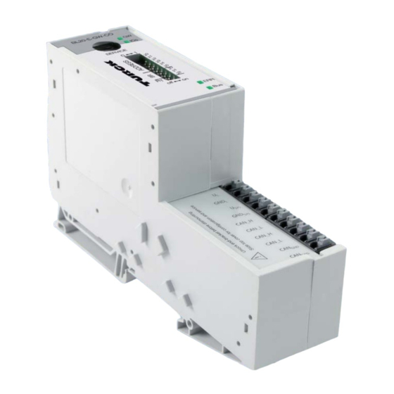
Technical Data Technical Data Figure 4-1: Gateway BL20-E-GW-CO BL20-E-GW-CO AType designation BLEDs for BL20 SERVICE module bus Cservice interface DDIP switch for the Node-ID EDIP switch for the bit rate FDIP switch for the terminating resistor GLEDs for CANopen Hfield supply Isystem supply JCANopen GND L... -
Page 36: General Technical Data Of A Station
Eco-Gateway for CANopen 4.2.1 General Technical Data of a Station Attention The auxiliary power supply must comply with the stipulations of SELV (Safety Extra Low Voltage) according to IEC 364-4-41. Table 4-1: Supply voltage/ auxiliary voltage General technical data of a station Nominal value 24 V DC (provision for other modules) - Page 37 Technical Data Relative humidity 5 to 95 % (indoor), Level RH-2, no condensation according to EN 61131-2/EN 50178 (storage at 45 °C, no function test) Climatic tests according to IEC 61131-2 Resistance to vibration according to IEC 61131-2 10 to 57 Hz, constant amplitude 0.075 mm / 0.003 inch, 1 g 57 to 150 Hz, constant acceleration 1 g...
-
Page 38: Technical Data For The Push-In Tension Clamp Terminals
Eco-Gateway for CANopen Approvals and Tests Table 4-2: Description Approvals and Approvals tests in preparation Tests (EN 61131-2) Cold DIN IEC 68-2-1, temperature -25 °C / -13 °F, duration 96 h; not in use Dry heat DIN IEC 68-2-2, Temperature +85 °C / 185 °F, duration 96 h; device not in use Damp heat, cyclic DIN IEC 68-2-30, temperature +55 °C / 131 °F, duration 2... -
Page 39: Connection Possibilities At The Gateways
Connection Possibilities at the Gateways Connection Possibilities at the Gateways The fieldbus connection as well as the power supply connection are realized via Push-in tension clamp terminals. Figure 4-3: Push-in tension clamp terminals GND L at the gateway U SYS GND SYS CAN_H CAN_L... - Page 40 Eco-Gateway for CANopen Note The shielding of the field bus cable is established directly on the mounting rail using a SHLD terminal. Note Equipotential bonding impedance ≤ 1/10 shielding impedance. D301108 1211 - BL20-ECO CANopen...
-
Page 41: Service Interface Connection
Service Interface Connection Service Interface Connection In order to connect the service interface on the gateway with a PC and the I/O-ASSISTANT software (project planning and diagnostics software), a cable with a pin assignment, different from the PS2 standard pin assignment, has to be used: I/O-ASSISTANT-KABEL-BL20/BL67 Attention Standard commercial cables will have to be rewired! -
Page 42: Setting The Node-Id
Eco-Gateway for CANopen Setting the Node-ID The setting of the Node-ID for the BL20-ECO gateway for CANopen is done via the DIP switches at the gateway. These DIP switches can be found under the gateway’s upper label. Figure 4-6: DIP-switches on the gateway Note Pull the label upwards out of the housing in order to reach the DIP-switches. -
Page 43: Setting The Bit Rate
Setting the Bit Rate Setting the Bit Rate The gateway BL20-E-GW-CO offers 3 DIP switches for setting the bit rate (BR). Figure 4-8: DIP switches for setting the bit rate Bit rate switch reserved 20 kBit/s 50 kBit/s 125 kBit/s 250 kBit/s 500 kBit/s 800 kBit/s... -
Page 44: Activating The Bus Terminating Resistor
Eco-Gateway for CANopen Activating the Bus Terminating Resistor If the gateway is used as the first or the last station in the bus communication, the fieldbus line has to be terminated using a terminating resistor. The BL20-E-GW-CO allows the activation of the resistors R using the last DIP-switch. -
Page 45: Acceptance Of The Bl20 Station Configuration
Acceptance of the BL20 Station Configuration Acceptance of the BL20 Station Configuration When making a new configuration of the BL20 station or an alteration of the existing station structure (“module list”), the current configuration must be accepted in the CANopen mirror of the BL20 gateway. The configuration acceptance at this device is done via the DIP switches set to address 0. -
Page 46: Status Indicators/ Diagnostic Messages Gateway
Eco-Gateway for CANopen Status Indicators/ Diagnostic Messages Gateway The gateway transmits the following diagnostics: the status of the BL20 station, the communication via the internal module bus, the communication to CANopen and the status of the gateway. Diagnostic messages are displayed in two ways: via individual LEDs via the software of the respective host system (i. - Page 47 Status Indicators/ Diagnostic Messages Gateway Table 4-6: Status Meaning Remedy LED displays Module bus not ready-to- – Check the correct mounting of the single operate BL20-modules Non-adaptable modification – Compare the planned BL20 station with flashing, of the physically connected the physical station.
- Page 48 Eco-Gateway for CANopen 4-16 D301108 1211 - BL20-ECO CANopen...
-
Page 49: Bl20 - Communication In Canopen
BL20 - Communication in CANopen Note The CANopen-description for BL20 can be found in a separate manual „BL×× CANopen- object register “ D301230 under www.turck.de. D301108 1211 - BL20-ECO CANopen... -
Page 50: Guidelines For Station Planning
Guidelines for Station Planning Module Arrangement........................2 6.1.1 Random Module Arrangement ......................2 6.1.2 Complete Planning ..........................2 Maximum System Extension ......................3 Power Supply ............................ 6 6.3.1 Power Supply to the Gateway ......................6 6.3.2 Module Bus Refreshing ........................6 6.3.3 Creating Potential Groups ........................ -
Page 51: Module Arrangement
Guidelines for Station Planning Module Arrangement 6.1.1 Random Module Arrangement The arrangement of the I/O modules within a BL20 station can basically be chosen at will. Nevertheless, it can be useful with some applications to group certain modules together. Note A mixed usage of gateways of the BL20 ECO and the BL20 standard product line and I/O modules of both product lines (base modules with tension clamp terminals) is possible without any problems. -
Page 52: Maximum System Extension
Maximum System Extension Maximum System Extension The maximum number of modules within BL20 station with the gateway BL20-E-GW-CO depends on the following factors: The maximum permissible number of 252 communication bytes which are transmitted via the module bus from the modules to the gateway must not be exceeded (see below Table 6-1: Communication bytes and nominal current consumptions of the BL20 modules). - Page 53 Guidelines for Station Planning Table 6-1: Module Number of Nominal current Communication communication bytes consumption at the module bytes and nominal current consumptions of the BL20 modules BL20-E-16DI-24VDC-P 15 mA BL20-16DI-24VDC-P 45 mA BL20-32DI-24VDC-P 30 mA BL20-1AI-I(0/4...20MA) 41 mA BL20-2AI-I(0/4...20MA) 35 mA BL20-1AI-U(-10/0...+10VDC) 41 mA...
- Page 54 Maximum System Extension Table 6-1: Module Number of Nominal current Communication communication bytes consumption at the module bytes and nominal current consumptions of the BL20 modules BL20-2RFID-× 30 mA BL20-E-1SWIRE 60 mA D301108 1211 - BL20-ECO CANopen...
-
Page 55: Power Supply
Guidelines for Station Planning Power Supply 6.3.1 Power Supply to the Gateway The gateways BL20-E-GW-CO offer an integrated power supply (see also Voltage Supply page 4-7) 6.3.2 Module Bus Refreshing The number of BL20 modules, which can be supplied via the internal module bus by the gateway or a Bus Refreshing module depends on the modules’... -
Page 56: C-Rail (Cross Connection)
Power Supply When using a digital input module for 120/230 V AC, it should be ensured that a potential group is created in conjunction with the Power Feeding module BL20-PF-120/230VAC-D. Attention It is not permitted to use the modules with 24 V DC and 120/230 V AC field supply in a joint potential group. - Page 57 Guidelines for Station Planning The C-rail can be used as required by the application, for example, as a protective earth (PE). In this case, the PE connection of each power distribution module must be connected to the mounting rail via an additional PE terminal, which is available as an accessory.
-
Page 58: Direct Wiring Of Relay Modules
Power Supply Figure 6-5: 8 DI 2 DO ECO 2 DO 2 DI Using the C-rail as protective earth BL20-E-GW-CO and for the power supply with relay SERVICE modules terminal GND L U SYS GND SYS CAN_H CAN_L CAN_H CAN_L CAN GND CAN GND C-rail (PE) -
Page 59: Protecting The Service Interface On The Gateway
Guidelines for Station Planning Protecting the Service Interface on the Gateway During operation, the label protecting the service interface and the DIP-switches must remain closed due to EMC and ESD. Plugging and Pulling Electronics Modules BL20 enables the pulling and plugging of electronics modules without having to disconnect the field wiring. -
Page 60: Guidelines For Electrical Installation
Guidelines for Electrical Installation General Notes............................ 2 7.1.1 General ..............................2 7.1.2 Cable Routing ............................2 – Cable Routing Inside and Outside of Cabinets ................. 2 – Cable Routing Outside Buildings ...................... 2 7.1.3 Lightning Protection ..........................3 7.1.4 Transmission Cables ..........................3 –... -
Page 61: General Notes
Guidelines for Electrical Installation General Notes 7.1.1 General Cables should be grouped together, for example: signal cables, data cables, heavy current cables, power supply cables. Heavy current cables and signal or data cables should always be routed in separate cable ducts or bundles. -
Page 62: Lightning Protection
Station x Cable Types Turck offers a variety of cable types for fieldbus lines as premoulded or bulk cables. The ordering information for the available cable types can be found in the TURCK BL20 catalogs. D301108 1211 - BL20-ECO CANopen... -
Page 63: Potential Relationships
Guidelines for Electrical Installation Potential Relationships 7.2.1 General The potential relationship of a PROFIBUS-DP system realized with BL20 modules is characterized by the following: The system’s power supply to the gateway, I/O modules and the field level is connected to the gateway. -
Page 64: Electromagnetic Compatibility (Emc)
Electromagnetic Compatibility (EMC) Electromagnetic Compatibility (EMC) BL20 products comply in full with the requirements pertaining to EMC regulations. Nevertheless, an EMC plan should be made before installation. Hereby, all potential electromechanical sources of interference should be considered such as galvanic, inductive and capacitive couplings as well as radiation couplings. -
Page 65: Protection Against High Frequency Interference Signals
Guidelines for Electrical Installation 7.3.5 Protection against high frequency interference signals Attention In order to comply with radiation limit values in accordance with EN 55 011/2 000, the supply lines for supplying the gateway with power are to be fed through a ferrite ring (PS416-ZBX- 405). -
Page 66: Emc Compliant Cabinet Installation
Electromagnetic Compatibility (EMC) 7.3.7 EMC Compliant Cabinet Installation Figure 7-4: EMC compliant cabinet installa- tion A Bonding straps Bonding straps connect inactive metal components, if it is not possible to create a large surface area contact. Use short bonding straps with large surface areas. B Mounting plates Mounting plates used to hold control components must have a large surface area contact with the cabinet housing. -
Page 67: Shielding Of Cables
Guidelines for Electrical Installation Shielding of cables Shielding is used to prevent interference from voltages and the radiation of interference fields by cables. Therefore, use only shielded cables with shielding braids made from good conducting materials (copper or aluminum) with a minimum degree of coverage of 80 %. The cable shield should always be connected to both sides of the respective reference potential (if no exception is made, for example, such as high-resistant, symmetrical, analog signal cables). - Page 68 Shielding of cables Connection 1 Connection 2 CAN_H --------- CAN_H CAN_L --------- CAN_L --------- Figure 7-5: Potential Shield compensation Potential compensation cable Reference potential Reference potential A potential compensation cable must have the following characteristics: Low impedance. In the case of compensation cables that are routed on both sides, the compensation line impedance must be considerably smaller than that of the shield connection (max.
-
Page 69: Switching Inductive Loads
Guidelines for Electrical Installation 7.4.2 Switching Inductive Loads In the case of inductive loads, a protective circuit on the load is recommended. 7.4.3 Protection against Electrostatic Discharge (ESD) Attention Electronics modules and base modules are at risk from electrostatic discharge when disassembled. - Page 70 BL20-Approvals for Zone 2/ Division 2 Note The Zone 2 - approval certificates for BL20 can be found in a separate manual for approvals D301255 on www.turck.de. D301108 1211 - BL20-ECO CANopen...
- Page 71 BL20-Approvals for Zone 2/ Division 2 D301108 1211 - BL20-ECO CANopen...
- Page 72 Glossary Acknowledge Acknowledgment of a signal received. Active metal component Conductor or conducting component that is electrically live during operation. Address Identifier of, e.g. a memory position, a system or a module within a network. Addressing Allocation or setting of an address, e. g. for a module in a network. Analog Infinitely variable value, e.
- Page 73 Glossary Bus line Smallest unit connected to a bus, consisting of a PLC, a coupling element for modules on the bus and a module. Bus system All units which communicate with one another via a bus. Capacitive coupling Electrical capacitive couplings occur between cables with different potentials. Typical sources of interference are, e.
- Page 74 Electrical components All objects that produce, convert, transmit, distribute or utilize electrical power (e. g. conductors, cable, machines, control devices). Electromagnetic compatibility – the ability of an electrical part to operate in a specific environment without fault and without exerting a negative influence on its environment. German acronym for European Standard.
- Page 75 Glossary Impedance Total effective resistance that a component or circuit has for an alternating current at a specific frequency. Inactive metal components Conductive components that cannot be touched and are electrically isolated from active metal components by insulation, but can adopt voltage in the event of a fault. Inductive coupling Magnetic inductive couplings occur between two cables through which an electrical current is flowing.
- Page 76 Polling Establish a Polled I/O Connection, i. e. a conventional Master/Slave relationship between a controller and a DeviceNet device. Potential compensation The alignment of electrical levels of electrical components and external conductive components by means of an electrical connection. Potential free Galvanic isolation of the reference potentials in I/O modules of the control and load circuits.
- Page 77 Glossary D301108 1211 - BL20-ECO CANopen...
- Page 78 Index address setting potential compensation ............. 4-10 ..........7-8 power distribution ............2-5 power supply ..............6-6 base modules Process Data Objects (PDOs) ..............2-7 .......... 3-3 baud rate product overview ..............4-11 ............2-1 BL20 components ............2-3 ................... 4-9 bus terminating resistor ..........
- Page 79 Index 10-2 D301108 1211 - BL20-ECO CANopen...
- Page 80 10-3 D301108 1211 - BL20-ECO CANopen...
- Page 81 Index 10-4 D301108 1211 - BL20-ECO CANopen...
- Page 82 Hans Turck GmbH & Co. KG 45472 Mülheim an der Ruhr Germany Witzlebenstraße 7 Tel. +49 (0) 208 4952-0 Fax +49 (0) 208 4952-264 E-Mail more@turck.com Internet www.turck.com...
Need help?
Do you have a question about the ECO-GATEWAY BL20 and is the answer not in the manual?
Questions and answers