Table of Contents
Advertisement
Quick Links
Advertisement
Chapters
Table of Contents

Related Manuals for turck BL67


Summary of Contents for turck BL67
- Page 1 BL67 – USER MANUAL PROFIBUS-DP...
- Page 2 No part of this manual may be reproduced in any form (printed, photocopy, microfilm or any other process) or processed, dupli- cated or distributed by means of electronic systems without written permission of Hans Turck GmbH & Co. KG, Mülheim an der Ruhr. Subject to alterations without notice.
- Page 3 Safety Notes! Before starting the installation Disconnect the power supply of the device. Ensure that devices cannot be accidentally restarted. Verify isolation from the supply. Earth and short circuit. Cover or enclose neighboring units that are live. Follow the engineering instructions of the device concerned. Only suitably qualified personnel in accordance with EN 50 110- 1/-2 (VDE 0 105 Part 100) may work on this device/system.
- Page 4 Devices that are designed for mounting in housings or control cabinets must only be operated and controlled after they have been installed with the housing closed. Desktop or portable units must only be operated and controlled in enclosed housings. Measures should be taken to ensure the proper restart of programs interrupted after a voltage dip or failure.
-
Page 5: Table Of Contents
Cable Type ....................2-6 Mixed Usage With Other Station Types............2-7 BL67-Gateway for PROFIBUS-DP Introduction ....................3-3 Function ......................3-4 Technical Information..................3-5 Structure Diagram ................... 3-6 Technical Data..................3-7 Connection Options ..................3-10 Fieldbus Connections................3-10 D300527 0906 - BL67 PBDP... - Page 6 Compressing Module Process Data............4-5 Connection to a Siemens S7 PLC............... 4-17 Reading-in the GSD File................ 4-17 Selecting the BL67 Gateway as a Slave..........4-19 Example of a Mixed Usage Configuration..........4-19 Setting Gateway Parameters..............4-20 Configuring the BL67 Station ..............4-21 Setting Parameters for BL67 Modules ..........
- Page 7 Example of Diagnostics with a Siemens S7-400 PLC ........ 4-26 Short-Circuit in a Digital Output Module ..........4-28 Planned but not Plugged I/O Module............ 4-29 Integration of BL67 Technology Modules Integration of the RS232 module ..............5-2 Data Image ....................5-2 Integration of the RS485/422 module ............
- Page 8 Protection against Electrostatic Discharge (ESD) ......... 7-12 Apendix Function Blocks for S7.................. 8-2 Function Blocks for BL67-1RSxxx ............8-2 Function block for BL67-1SSI..............8-15 Nominal Current Consumption of Modules at PROFIBUS-DP ....8-22 Parameter Gateway – Assignment in Hexadecimal Format......8-24 Parameter 4 ...................
- Page 9 About this Manual Documentation Concept ..............2 General Information................3 Prescribed Use ....................3 Notes Concerning Planning /Installation of this Product ......3 Description of Symbols Used ............4 List of Revisions ................5 D300527 0906 - BL67 PBDP...
-
Page 10: About This Manual
® gateway of the busstop BL67-system. The following chapters contain a short BL67 system description, a description of the field bus system PROFIBUS-DP, exact informa- tion about function and structure of the BL67 PROFIBUS-DP gateway as well as all bus specific information concerning the connection to automation devices, the maximum system extension etc. -
Page 11: General Information
Notes Concerning Planning /Installation of this Product Warning All respective safety measures and accident protection guidelines must be considered carefully and without exception. D300527 0906 - BL67 PBDP... -
Page 12: Description Of Symbols Used
This sign can be found next to all general notes that supply impor- tant information about one or more operating steps. These specific notes are intended to make operation easier and avoid unnecessary work due to incorrect operation. D300527 0906 - BL67 PBDP... -
Page 13: List Of Revisions
Chapter Subject/ changed Table 1: List of revisions Description Chap. 5 Corrections in the data image of the technology modules Note The publication of this manual renders all previous editions invalid. D300527 0906 - BL67 PBDP... - Page 14 About this Manual D300527 0906 - BL67 PBDP...
-
Page 15: Bl67 Philosophy
BL67 Philosophy The Basic Concept ................2 Flexibility......................2 Convenient Handling ...................3 BL67 Components ................4 Gateways.....................4 Electronic Modules..................5 – Power Feeding Modules ................5 Base Modules....................6 End Plate ....................6 D300527 0906 - BL67 PBDP... -
Page 16: The Basic Concept
Analog input and output modules Technology modules (RS232 interface, ...) A complete BL67 station counts as one station on the bus and therefore occupies one fieldbus address in any given fieldbus struc- ture. A BL67 station consists of a gateway, power distribution modules and I/O modules. -
Page 17: Convenient Handling
The Basic Concept Convenient Handling All BL67 modules, with the exception of the gateway, consist of a base module and an electronic module. The gateway and the base modules are snapped onto a mounting rail or are directly mounted onto a mounting plate. The electronic modules are plugged onto the appropriate base modules. -
Page 18: Bl67 Components
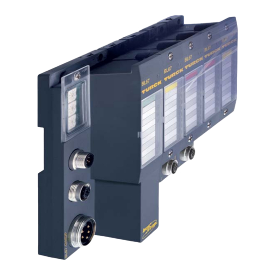
The gateway connects the fieldbus to the I/O modules. It is respon- sible for handling the entire process data and generates diagnostic information for the higher-level master and the software tool I/O-ASSISTANT. Figure 2: BL67 gateway for PROFIBUS-DP D300527 0906 - BL67 PBDP... -
Page 19: Electronic Modules
Note For detailed information about the individual BL67 I/O components, please refer to the chapters 2 to 8 of the manual „BL67- I/O mod- ules“ (TURCK Documentation-No.: German D300572; English: D300529). The „Appendix“ to the manual mentioned above contains (amongst others) a list of all BL67 components and the assignment of elec- tronic modules to base modules. -
Page 20: Base Modules
Figure 4: example of a base module End Plate An end plate on the right-hand side physically completes the BL67 station. It protects the module bus connections of the last base module in a station and guarantees the protection class IP67. -
Page 21: Profibus-Dp
Maximum System Extension .............. 3 Maximum System Extension without Repeaters.........3 Maximum System Extension with Repeaters..........4 – Maximum Distances / Bus Lengths with and without Repeaters ..........5 Cable Type..................6 Mixed Usage With Other Station Types ..........7 D300527 0906 - BL67 PBDP... -
Page 22: Decentralized Periphery
European fieldbus standard EN 50170. Topology PROFIBUS-DP communicates via a shielded twisted pair cable according to the RS485 standard. The network topology represents a linear structure with active bus termination on both ends. D300527 0906 - BL67 PBDP... -
Page 23: Maximum System Extension
PROFIBUS-DP master, as well as a gateway, which controls the communication of the various BL67 modules. Each BL67-gateway is a passive node (slave) in the PROFIBUS-DP- structure and occupies one fieldbus address. Maximum System Extension without Repeaters Without a repeater, a PROFIBUS-DP line can consist of a maximum of 31 BL67 stations and a master. -
Page 24: Maximum System Extension With Repeaters
PROFIBUS-DP card repeaters PROFIBUS-DP Bus segment 1 BL67 gateway 1 BL67 gateway 30 Repeater 1 BL67 gateway 1...30 Bus segment 2 Repeater 2 BL67 gateway 1...30 Bus segment 3 Repeater 3 BL67 gateway 1...31 D300527 0906 - BL67 PBDP... - Page 25 (PLC or PC) plus a maximum of 30 gateways per bus segment. The maximum number of all possible stations is manufacturer specific and is for example, at its limit with 121 BL67 gateways and three re- peaters. The maximum number of 125 bus stations must not be ex- ceeded.
-
Page 26: Cable Type
Type A 135 to 165 Ω (3 to 20 MHz) Characteristic impedance Distributed capacitance < 30 nF/km < 110 Ω/km Loop resistance Wire diameter > 0.64 mm Wire cross-section > 0.34 mm 220 Ω Terminating resistor D300527 0906 - BL67 PBDP... -
Page 27: Mixed Usage With Other Station Types
Mixed Usage With Other Station Types Mixed Usage With Other Station Types In addition to BL67 gateways, it is possible to integrate other station types (for example, TURCK-PROFIBUS-DP modules like BL20 or ® piconet , or devices from third party manufacturers which have been certified according to DIN 19 245 Part 3). - Page 28 PROFIBUS-DP D300527 0906 - BL67 PBDP...
-
Page 29: Bl67-Gateway For Profibus-Dp
Module Description According to Type.............40 Example of a PROFIBUS-DP Configuration..........42 System Description ...................43 – Parameter Configuration Data ...............43 – Diagnostic Data ..................44 Status Indicators/Diagnostic Messages Gateway......45 Diagnostic Messages via LEDs ..............45 Diagnostic Messages via the Software .............51 D300527 0906 - BL67 PBDP... - Page 30 Diagnosis ..................52 Device Related diagnosis ................52 Device-/ identifier - and channel specific diagnosis .........53 Description of the Gateway Diagnosis Bits ..........55 Module diagnosis ..................60 – Device related diagnosis messages ............60 – Channel specific diagnosis messages ..........69 D300527 0906 - BL67 PBDP...
-
Page 31: Introduction
Introduction Introduction This chapter contains a description of BL67 gateways for the stan- dardized fieldbus PROFIBUS-DP. The chapter is divided up as follows: a description of functions, general and specific technical data, a description of addressing and status displays, and param- eter assignment. -
Page 32: Function
The BL67-gateway for PROFIBUS-DP is available with a maximum baud rate of 12 MBaud. WAIT_PRM When the BL67 gateway has the “WAIT_PRM” status, it is not possible to check the parameters in the parameter telegram of the PROFIBUS-DP master due to the large number of module combina- tions and module variants. -
Page 33: Technical Information
Technical Information Technical Information Figure 8: BL67 gateway for PROFIBUS-DP A Power supply B DP-IN C DP-OUT D Service- interface E rotary coding switches F Designation G Module bus LEDs H LEDs for voltage supply PBDP-LEDs D300527 0906 - BL67 PBDP... -
Page 34: Structure Diagram
BL67-Gateway for PROFIBUS-DP Structure Diagram The BL67 gateway has the following structure: Figure 9: BL67- gateway structure system bus service memory interface PS/2 communi- cation DP OUT interface module bus interface DP IN 5 VDC 24 VDC power short circuit... -
Page 35: Technical Data
4 A short-circuit and overload protec- tion of the sensor supply from gateway or power feeding module Isolation voltages 0 V DC (PROFIBUS-DP/ service interface) 0 V DC (PROFIBUS-DP/ module bus) 1000 V DC to U D300527 0906 - BL67 PBDP... - Page 36 Immunity to interference Static electricity according to IEC 61131-2 Electromagnetic HF fields according to IEC 61131-2 Fast transients (Burst) according to IEC 61131-2 Conducted interferences according to IEC 61000-4-6 induced by HF fields 10 V Criteria A D300527 0906 - BL67 PBDP...
- Page 37 This device can cause radio disturbances in residential areas and in small industrial areas (residential, business and trading). In this case, the operator can be required to take appropriate measures to sup- press the disturbance at his own cost. D300527 0906 - BL67 PBDP...
-
Page 38: Connection Options
Shield connection/ protective earth Note Please note, the special SUB-D connector should have 4 inductanc- es (pro 100 nH to 110 nH) in the P and the N supply wires (recom- mended by the PROFIBUS User Organization). 3-10 D300527 0906 - BL67 PBDP... -
Page 39: Fieldbus Termination
V Feed-in of nominal voltage for input modules (sensor supply); also used for the generation of the system supply voltage white ) Feed-in of nominal voltage for output modules (can be switched off separately) D300527 0906 - BL67 PBDP 3-11... -
Page 40: Service Interface Connection
The I/O-ASSISTANT-cables have a PS/2 male connector (connec- tion for female connector on gateway) and a SUB-D female connector (connection for male connector on PC). Figure 14: PS/2 male con- nector on the con- nection cable to the gateway (top view) 3-12 D300527 0906 - BL67 PBDP... -
Page 41: Connection Using Commercially Available Cables
PC (top view) Connection Using Commercially Available Cables A further possibility to connect PC and BL67 gateway is to use a commercially available connection and adapter cable. The connection shown in the following figure (PS2-male/ PS2-male) is a 6-wire 1:1 connection. - Page 42 Standard PS/2 BL67 gateway: Pin- Male connector male connector PS/2 female A not supported connector by all adapter cables. 4, 6 DTR, DSR (from gateway) DATA not connected – – n.c. (DATA2) /CtrlMode n.c. (CLK2) 3-14 D300527 0906 - BL67 PBDP...
-
Page 43: Address Setting
Address Setting Address Setting BL67 gateway addressing on PROFIBUS-DP is performed via the three decimal rotary coding-switches. These switches are posi- tioned next to the service interface. Figure 19: Decimal coding switches for ad- X 100 dress setting X 10 Attention A maximum of 126 addresses (000 to 125) can be allocated. -
Page 44: Setting Parameters
BL67-Gateway for PROFIBUS-DP Setting Parameters Gateway Parameters BL67 gateways for PROFIBUS-DP require 5 parameter bytes. These describe exclusively the behavior of the gateway itself. The first three parameters are defined by the PROFIBUS-DP standard. Description and Allocation of Gateway Parameters The texts in the columns “Parameter name“... - Page 45 Depending on their configuration, these modules set their outputs either to “0” or to a default value, or maintain the original values. The non-configured analog output modules set their outputs to “0”. D300527 0906 - BL67 PBDP 3-17...
- Page 46 Depending on their configuration, these modules set their outputs either to “0” or to a default value, or maintain the original values. The non-configured analog output modules set their outputs to “0”. 3-18 D300527 0906 - BL67 PBDP...
- Page 47 This parameter influences the process data! Bit 1: Diagnostics from modules activate Diagnostic messages from the module bus stations are made known to the fieldbus master as extended diagnostics. D300527 0906 - BL67 PBDP 3-19...
- Page 48 Bit 3: Station configuration do not allow When commissioning the BL67 changes station, the actual list of modules must match exactly the module list planned in the configuration software of the master. 3-20 D300527 0906 - BL67 PBDP...
- Page 49 Value Meaning Gateway Parameter parameters name allow changes When the BL67 station is put into A default settings operation by the fieldbus master, the actual list of modules can differ slightly from the list of modules planned in the configura- tion software of the master: –...
-
Page 50: Module Parameters
Digital input 0 0 = normal standard mod- 1 = inverted ule description Digital input 3 n + 2 0 Operation Mode 0 = normal Group A 1 = open-circuit monitoring Operation Mode Group B 3-22 D300527 0906 - BL67 PBDP... - Page 51 1 = 12 bit (left-justified) standard mod- ule description Diagnostic 0 = release 1 = block Channel 0 = activate 1 = deactivate – Channel 0 n + 1 assignment similar to byte n = channel 0 D300527 0906 - BL67 PBDP 3-23...
- Page 52 1 = 12 bit (left-justified) Diagnostic 0 = release 1 = block Channel 0 = activate 1 = deactivate – Channel 1 n + 1 assignment similar to byte n = channel 0 3-24 D300527 0906 - BL67 PBDP...
- Page 53 1110 = Resistance, 0...400 Ω 1111 = Resistance, 0...1000 Ω n + 2 assignment similar to byte n = channel 0 n + 3 assignment similar to byte n + 1 = channel 0 D300527 0906 - BL67 PBDP 3-25...
- Page 54 0111 = type T, -270...400 °C 1000 = ±50 mV 1001 = ±100 mV 1010 = ±500 mV 1011 = ±1000 mV – Channel 1 n + 1 assignment similar to byte n = channel 0 3-26 D300527 0906 - BL67 PBDP...
-
Page 55: Standard Module Description
+ 1 assignment similar to byte n = channel 0 – Channel 2 n + 2 assignment similar to byte n = channel 0 – Channel 3 n + 3 assignment similar to byte n = channel 0 D300527 0906 - BL67 PBDP 3-27... - Page 56 1001 = 90 mA 1010 = 100 mA 1011 = 110 mA 1100 = 120 mA n + 1 0 Overcurrent monitoring 0 = deactivate 1 = activate Open circuit monitoring 0 = deactivate 1 = activate 3-28 D300527 0906 - BL67 PBDP...
- Page 57 „output substitute value“. – Channel 1 n + 3 assignment similar to byte n = channel 0 n + 4 assignment similar to byte n + 1 and n + 2 n + 5 D300527 0906 - BL67 PBDP 3-29...
- Page 58 „output substitute value“. – Channel 1 n + 3 assignment similar to byte n = channel 0 n + 4 assignment similar to byte n + 1 and n + 2 n + 5 3-30 D300527 0906 - BL67 PBDP...
- Page 59 Digital input 1 0 = normal standard mod- 1 = inverted ule description Digital input 3 n + 2 0 Output on 0 = automatic recovery overcurrent 1 1 = controlled recovery Output on overcurrent 4 D300527 0906 - BL67 PBDP 3-31...
- Page 60 + 2 0 Output on 0 = automatic recovery overcurrent 1 1 = controlled recovery Output on overcurrent 8 n + 3 0 Output 1 0 = deactivate 1 = activate Output 3 3-32 D300527 0906 - BL67 PBDP...
- Page 61 00 = none 01 = odd 10 = even data bits 0 = 7 1 = 8 5, 4 data flow control 00 = none 01 = XON/XOFF 10 = RTS/CTS 11 = reserved D300527 0906 - BL67 PBDP 3-33...
- Page 62 6 of the process input data (independent of „diag- nostic“) Byte 7 contains the status byte, user data are displayed in bytes 0 - 5. Diagnostic 0 = release 1 = block 3-34 D300527 0906 - BL67 PBDP...
- Page 63 00 = none 01 = odd 10 = even data bits 0 = 7 1 = 8 5, 4 data flow control 00 = none 01 = XON/XOFF 10 = RTS/CTS 11 = reserved D300527 0906 - BL67 PBDP 3-35...
- Page 64 6 of the process input data (independent of „diag- nostic“) Byte 7 contains the status byte, user data are displayed in bytes 0 - 5. Diagnostic 0 = release 1 = block 3-36 D300527 0906 - BL67 PBDP...
- Page 65 Invalid bits (LSB) 0000 to 1111 6 to Invalid bits (MSB) 000 to 111 reserved n + 3 4 to reserved Sensor idle data 0 = activate signal test 1 = deactivate 7 to reserved D300527 0906 - BL67 PBDP 3-37...
- Page 66 Default 3 = 300 ms n + 9 Life Time Factor Factor which defines how often a node is allowed not to answer a request or to exceed the Guard-Time (values 0 to 255); default = 3 3-38 D300527 0906 - BL67 PBDP...
- Page 67 000 = 1000 kbps 001 = 500 kbps 010 = 250 kbps 011 = 125 kbps 100 = 50 kbps 101 = 20 kbps 111 = 10 kbps Terminating resistor 0 = deactivate 1 = activate reserved D300527 0906 - BL67 PBDP 3-39...
-
Page 68: Module Description In The Electronic Device Data Sheets (Gsd)
Modules cannot be unmistakably identified using this identification. Advantage: Replacement modules need not be of an identical type to be accepted by the BL67 gateway. This means that “related” modules with identical process data lengths can be used. Thus, it is possible to exchange a 4 DO 24 V DC module with 0.5A with a 4 DO... - Page 69 Module Description in the Electronic Device Data Sheets modules possible. The BL67 gateway accepts replacement modules only of an identical type. Figure 21: Description according to type of the digital input module BL67-4DO-0.5A Options by the descriptions of modules Typified module description: Special identification format:...
-
Page 70: Example Of A Profibus-Dp Configuration
Example of a station configuration: Module A: 4DI Module B: 4DI Module C: 4DI Module D: 8 DI Module E: 2 AI-I Module F: 2 AO-I Module G: 4 DO-0.5A 3-42 D300527 0906 - BL67 PBDP... -
Page 71: System Description
3 Module bus station C: Not configurable 4 Module bus station D: Not configurable 5 Module bus station E (per channel): bit 0 = 0: Current mode: 0...20 mA bit 0 = 1: Current mode: 4...20 mA D300527 0906 - BL67 PBDP 3-43... -
Page 72: Diagnostic Data
6 Module F: No diagnostic data available 7 Module G: bit 0: Overcurrent (short circuit channel 0) bit 1: Overcurrent (short circuit channel 1) bit 2: Overcurrent (short circuit channel 2) bit 3: Overcurrent (short circuit channel 3) 3-44 D300527 0906 - BL67 PBDP... -
Page 73: Status Indicators/Diagnostic Messages Gateway
Status Indicators/Diagnostic Messages Gateway The gateway transmits the following diagnostics: the status of the BL67 station, the communication via the internal module bus, the communication to PROFIBUS-DP and the status of the gateway. Diagnostic messages are displayed in two ways:... - Page 74 – Deactivate the flashing I/O-ASSISTANT Force I/O-ASSISTANT Force 1 Hz Mode. Mode. Green, Maximum number of – Check the number of flashing modules at the modules connected to gateway is exceeded. the gateway, dismount modules 3-46 D300527 0906 - BL67 PBDP...
- Page 75 1 Hz data transfer possible modules. CPU not supplied – Check the system supply at the gateway. Green Module bus and CPU running D300527 0906 - BL67 PBDP 3-47...
- Page 76 Short circuit or over- – Automatic restart load at sensor supply when debugging. → sensor supply is switched off No voltage supply. – Check the wiring of the voltage supply at the gateway 3-48 D300527 0906 - BL67 PBDP...
- Page 77 PLC software. Bus Off No voltage supply – Wait for the firmware- download to be completed. – After firmware-down- load: hardware-error, replace the gateway. Green Communication – between gateway and PROFIBUS-DP master is error free. D300527 0906 - BL67 PBDP 3-49...
- Page 78 The 1 Hz not be used is set at the addresses 000 and gateway addresses > 125 must not be set. See also Section “Address Setting“, Page 3-15. 3-50 D300527 0906 - BL67 PBDP...
-
Page 79: Diagnostic Messages Via The Software
The diagnostic messages are displayed in the corresponding soft- ware of the PROFIBUS-DP master as diagnostic bytes. For the meaning of the individual diagnostic bits, please refer to the Section “Diagnosis“ in this chapter. D300527 0906 - BL67 PBDP 3-51... -
Page 80: Diagnosis
BL67-Gateway for PROFIBUS-DP Diagnosis BL67 offers 2 possibilities for the representation of diagnostic information: device related diagnosis: diagnosis-header + 2 byte gateway-diagnosis + maximum of 61 byte module diagnosis device-/ identifier-/ channel-specific diagnosis: diagnosis-header + device related diagnosis → 2 byte gateway diagnosis + identifier related diagnosis →... -
Page 81: Device-/ Identifier - And Channel Specific Diagnosis
2 byte gateway diagnosis + max. 61 byte module diagnosis). Byte 8 and gateway diagnosis: Byte 9 Byte 8, bit 0 shows, for example, if another module in the station sends diagnosis information (bit 0 = 1), or not (bit 0 = 0). D300527 0906 - BL67 PBDP 3-53... - Page 82 Bit 5 to bit 7 define, if the module is a bit-, byte- or word- oriented module: 001 = bit-oriented 010 = 2 bit-oriented 011 = 4 bit-oriented 110 = word-oriented 111 = double word-oriented 3-54 D300527 0906 - BL67 PBDP...
-
Page 83: Description Of The Gateway Diagnosis Bits
DP standard. Gateway warnings Module diagnostics available 0 = No module bus station is signaling a diagnostic. 1 = At least one module bus station with diagnostic function is signaling a diag- nostic. reserved D300527 0906 - BL67 PBDP 3-55... - Page 84 The constellation of the module bus station that is set in the configuration software (CheckConfig-Cmd) of the corresponding fieldbus master serves as a refer- ence. 3-56 D300527 0906 - BL67 PBDP...
- Page 85 0...1 reserved Module bus error 0 = Communication with the module bus station on the module bus is possible. 1 = Communication with the module bus station on the module bus is not possible. D300527 0906 - BL67 PBDP 3-57...
- Page 86 The constellation of the module bus station, set in the configuration software of the corresponding fieldbus master serves as a refer- ence. 3-58 D300527 0906 - BL67 PBDP...
- Page 87 No process data exchange is taking place from the fieldbus master to the output modules. reserved Note Up to 61 bytes of module-specific diagnostic errors can follow. D300527 0906 - BL67 PBDP 3-59...
-
Page 88: Module Diagnosis
2 (sensor supply B) overcurrent sensor 3 (sensor supply C) overcurrent sensor 4 (sensor supply D) n + 1 open circuit K1(channel 0 and 2) open circuit K2 (channel 1 and 3) 3-60 D300527 0906 - BL67 PBDP... - Page 89 4 to 20 mA n + 1 measurement value range error (ch. 1) open circuit BL67-2AI-V Table 33: Diagnosis Diagnosis BL67-2AI-V byte measurement value range error (ch. 0) n + 1 measurement value range error (ch. 1) D300527 0906 - BL67 PBDP 3-61...
- Page 90 (only in temperature measurement ranges) value No PT1000 sensor (cold junction compensation) 3 to 7 reserved n + 1 0 to 7 see channel 0 (ch. 1) 3-62 D300527 0906 - BL67 PBDP...
- Page 91 (ch. 1 to 3) BL67-4DO-0.5A-P Table 37: Diagnosis Diagnosis BL67-4DO-0.5A-P byte overcurrent (short-circuit channel 0) overcurrent (short-circuit channel 3) BL67-4DO-2A-P Table 38: Diagnosis Diagnosis BL67-4DO-2A-P byte overcurrent (short-circuit channel 0) overcurrent (short-circuit channel 3) D300527 0906 - BL67 PBDP 3-63...
- Page 92 + 1 overcurrent (short-circuit channel 8) overcurrent (short-circuit channel 15) BL67-4DO-2A-N Table 41: Diagnosis Diagnosis BL67-4DO-2A-N byte overcurrent (short-circuit channel 0) overcurrent (short-circuit channel 1) overcurrent (short-circuit channel 2) overcurrent (short-circuit channel 3) 3-64 D300527 0906 - BL67 PBDP...
- Page 93 1 (sensor supply A) overcurrent sensor 2 (sensor supply B) overcurrent sensor 3 (sensor supply C) overcurrent sensor 4 (sensor supply D) n + 1 overcurrent K1 overcurrent K2 overcurrent K3 overcurrent K4 D300527 0906 - BL67 PBDP 3-65...
- Page 94 2 (sensor supply B) overcurrent sensor 3 (sensor supply C) overcurrent sensor 4 (sensor supply D) n + 1 overcurrent K1 overcurrent K2 overcurrent K3 overcurrent K4 overcurrent K5 overcurrent K6 overcurrent K7 overcurrent K8 3-66 D300527 0906 - BL67 PBDP...
- Page 95 BL67-1RS485/ byte parameterization error hardware failure data flow control error frame error buffer overflow BL67-1SSI Table 47: Diagnosis Diagnosis BL67-1SSI byte SSI group diagnostics open circuit sensor value overflow sensor value underflow parameterization error D300527 0906 - BL67 PBDP 3-67...
- Page 96 Communication error/Guard Time timeout Table 50: Name Global diagnostic Emergencies transmitted since module start data CVI module (DiagCVI) Node address not within permissible range (1-8) Overcurrent VC (valve power supply) Overcurrent VE (valve electronic power supply) 3-68 D300527 0906 - BL67 PBDP...
- Page 97 1 (sensor supply A) overcurrent sensor 2 (sensor supply B) overcurrent sensor 3 (sensor supply C) overcurrent sensor 4 (sensor supply D) open circuit K1(channel 0 and 2) open circuit K2 (channel 1 and 3) D300527 0906 - BL67 PBDP 3-69...
- Page 98 BL67-2AI-I Table 54: Value Diagnosis BL67-2AI-I (dec.) A Only in the measurement value range error measurement open circuit range 4 to 20 mA BL67-2AI-V Table 55: Value Diagnosis BL67-2AI-U (dec.) measurement value range error 3-70 D300527 0906 - BL67 PBDP...
- Page 99 (only in the temperature measurement ranges) No PT1000 sensor (cold junction compensation) BL67-4AI-V/I Table 58: Value Diagnosis BL67-4AI-V/I (dec.) measurement value range error BL67-4DO-0.5A-P Table 59: Value Diagnosis BL67-4DO-0.5A-P (dec.) overcurrent (short-circuit channel 0) D300527 0906 - BL67 PBDP 3-71...
- Page 100 – byte 1, bit 0 to 7 = channel 8 to 15 BL67-4DO-2A-N Table 63: Value Diagnosis BL67-4DO-2A-N (dec.) overcurrent (short-circuit channel 0) BL67-8DO-0.5A-N Table 64: Value Diagnosis BL67-8DO-0.5-N (dec.) overcurrent (short-circuit channel 0) 3-72 D300527 0906 - BL67 PBDP...
- Page 101 Diagnosis BL67-4DI4DO-PD Table 65: Value Diagnosis BL67-4DI4DO-PD (dec.) overcurrent sensor 1 overcurrent sensor 2 overcurrent sensor 3 overcurrent sensor 4 overcurrent K1 overcurrent K2 overcurrent K3 overcurrent K4 D300527 0906 - BL67 PBDP 3-73...
- Page 102 K1 overcurrent K2 overcurrent K3 overcurrent K4 overcurrent K5 overcurrent K6 overcurrent K7 overcurrent K8 BL67-1RS232 Table 67: Value Diagnosis BL67-1RS232 (dec.) parameterization error hardware failure data flow control error frame error buffer overflow 3-74 D300527 0906 - BL67 PBDP...
- Page 103 Table 68: Value Diagnosis BL67-1RS485/422 (dec.) parameterization error hardware failure frame error buffer overflow BL67-1SSI Value Diagnosis Table 69: BL67-1SSI (dec.) SSI group diagnostics open circuit sensor value overflow sensor value underflow parameterization error D300527 0906 - BL67 PBDP 3-75...
- Page 104 BL67-Gateway for PROFIBUS-DP 3-76 D300527 0906 - BL67 PBDP...
-
Page 105: Connections To Automation Devices
Reading-in the GSD File................17 – Reading-in the GSD Files before Starting the Software ......17 – Reading-in the GSD Files after Starting the Software ......17 Selecting the BL67 Gateway as a Slave............19 Example of a Mixed Usage Configuration..........19 Setting Gateway Parameters..............20 Configuring the BL67 Station ..............21... -
Page 106: Introduction
PROFIBUS-DP is based on DIN 19 245, Parts 1 and 3, and has been integrated into the European fieldbus standard EN 50 170. Note BL67 gateways can only be used as slaves on PROFIBUS-DP. Gateways have no master function. All manufacturers of control systems offer plug-in network cards for their PLCs, to which BL67 gateways can easily be connected. -
Page 107: Addressing
This guarantees trouble-free communication for the entire bus. Attention If a BL67 gateway is the first or last station in the bus structure, then a special bus connector with either an integrated or switchable bus terminating resistor must be used. -
Page 108: Electronic Device Data Sheets (Gsd)
Module description according to type The configured list of modules is displayed with extended identifica- tion (special identification format), which makes an exact identifica- tion of modules possible. The BL67 gateway accepts modules exchanged only with modules of an identical type. Note Please read Chapter 3, Section “Module Description in the Electron-... -
Page 109: Compressing Module Process Data
BL67 stations, as well as further functions, for example, the grouping of BL67 modules of the same type to blocks. The aim of creating these blocks is to save configuration bytes and at the same time increase the amount of parameters and process data transmitted via the internal module bus. - Page 110 Attention There are no plans for the use of multiple module blocks which ex- ceed the limit of 1 byte process data (“3*T-BL67...” and “4*T-BL67...” with modules with 4 DI or 4 DO). Follow-up modules (module descriptions according to type or standard, identified in the GSD file by “..S-BL67...“...
- Page 111 Example 2: This example shows the number of process data bytes for the following module combination: 1. module: BL67-4DO-0.5A-P 2. module: BL67-4DO-2A-P 3. module: BL67-4DO-2A-P 4. module: BL67-4DO-0.5A-P 5. module: BL67-4DO-0.5A-P D300527 0906 - BL67 PBDP...
- Page 112 5 modules Not compressed 5 Bytes BL67-4DO-xx Compressed: 3 Bytes standard description Compressed: 3 Bytes description according to type Compressed: 3 Bytes description according to type, multiple module blocks D300527 0906 - BL67 PBDP...
-
Page 113: Example Of Compressing Module Process Data
These are explained by the following example: Station configuration: Table 72: Module Stations configu- Gateway PBDP ration of the example station BL67-4DI-24VDC-P BL67-8DI-24VDC-P BL67-4DI-24VDC-P BL67-4DI-24VDC-P BL67-4DI-24VDC-P BL67-2AO-I BL67-4DO-0.5A-P BL67-4DO-0.5A-P BL67-4DO-0.5A-P BL67-4DI-24VDC-P BL67-2AI-V BL67-4DO-2A-P D300527 0906 - BL67 PBDP... -
Page 114: Standard Module Description
Connections to Automation Devices An overview of possible configuration options for the depicted BL67 station are shown in the following tables. The entries in the columns “Module (*)” and “Module (**)” mean: Module (*) Order of modules: non compressed/compressed (module block) - Page 115 Electronic Device Data Sheets (GSD) Figure 22: Use of standard module descrip- tion in a Siemens PLC system D300527 0906 - BL67 PBDP 4-11...
- Page 116 I/O modules with module descrip- compressed tion according to modules type Gateway 4 DI T-BL67-4DI-... 8 DI T-BL67-8DI-... 4 DI T-BL67-4DI-... 4 DI ..T-BL67-4DI-... 4 DI T-BL67-4DI-... 2AO-I T-BL67-2AO-I-... 2* T-BL67-4DO-0.5A T-BL67-4DO-0.5A ..T-BL67-4DI-... 2AI-V T-BL67-2AI-V T-BL67-4DO-2A... 4-12 D300527 0906 - BL67 PBDP...
- Page 117 Attention It is not permitted for the total of the process data lengths of all the modules grouped to a module block to exceed 1 Byte. D300527 0906 - BL67 PBDP 4-13...
- Page 118 The follow-up modules can be used in both the standard module description and in the description according to type. Note Exception: Multiple modules (“2*T-BL67...”) cannot be used as fol- low-up modules. When modules are plugged onto planned empty slots, the commu- nication of the fieldbus master depends on the gateway parameter “Station configuration”...
-
Page 119: Module Description According To Type
“original” module. Note The option of creating blocks of modules can be decisively influ- enced during configuration of an BL67 station. Module Description According to Type If the original module is identified according to type, all follow-up modules can have different process data lengths. The description according to type guarantees the unmistakable identification of the electronic module. - Page 120 This means, in contrast to the agreements reached above, it is not pos- sible to consider modules that are not mounted next to one another as blocks. 4-16 D300527 0906 - BL67 PBDP...
-
Page 121: Connection To A Siemens S7 Plc
BL67 gateway with a Siemens S7 PLC. Reading-in the GSD File The GSD files for BL67 must be read into the software before you can begin with the initial configuration. There are two procedures possible for reading-in the files: Reading-in the GSD Files before Starting the Software Copy the GSD files “TRCKFF2F.gsd”... - Page 122 The GSD files are listed as separate entries in the hardware catalog following correct installation. Note The exact configuration procedure can be found in the operators manual, which is supplied with the software. 4-18 D300527 0906 - BL67 PBDP...
-
Page 123: Selecting The Bl67 Gateway As A Slave
Connection to a Siemens S7 PLC Selecting the BL67 Gateway as a Slave To insert a BL67 station as a slave, select the required entry from the hardware catalog. Figure 26: Inserting a BL67 station as a slave Example of a Mixed Usage Configuration You can extend the fieldbus structure as you wish in the manner described above;... -
Page 124: Setting Gateway Parameters
Connections to Automation Devices Setting Gateway Parameters To set the gateway parameters, double-click the corresponding BL67 station. In the window which opens, click the “Assigning Parameters” button to open the dialog box where you can set the gateway parameters. Table 77:... -
Page 125: Configuring The Bl67 Station
Selecting a BL67 module Setting Parameters for BL67 Modules If BL67 modules are entered whose parameters can be set, it is possible to open the dialog box with the relevant options by double- clicking the corresponding module. The parameters of the individual BL67 modules are described in Chapter 3, Section “Module Parameters“... -
Page 126: Error Diagnostics (Station Diagnostics) When Connected To A Siemens S7 Plc
Diagnostic options for gateways are described in Chapter 3. Function Blocks for S7 In the appendix of this manual you can find a detailed description of the S7 functions blocks for the BL67 technology modules (e.g. BL67-1RS232). 4-22 D300527 0906 - BL67 PBDP... -
Page 127: Diagnostics On Profibus-Dp
Table 78: Module Number of Diagnostic Diagnostic bytes diagnostic bytes in of the example bytes PROFIBUS-DP station BL67-GW-DP 7 to 9 BL67-4DI-24VDC-P BL67-8DI-24VDC-P BL67-4DI-24VDC-P BL67-4DI-24VDC-P BL67-4DI-24VDC-P BL67-2AO-I BL67-4DO-0.5A-P BL67-4DO-0.5A-P BL67-4DO-0.5A-P BL67-4DI-24VDC-P BL67-2AI-V BL67-4DO-0.5A-P D300527 0906 - BL67 PBDP 4-23... - Page 128 (Length recognition and type of DP diagnostic) GW BL67-GW-DP Gateway diagnostic byte 1 Byte 8 (gateway warning) GW BL67-GW-DP Gateway diagnostic byte 2 Byte 9 (gateway error) BL67-4DO-0.5A-P Module diagnostic Byte 10 BL67-4DO-0.5A-P Module diagnostic Byte 11 4-24 D300527 0906 - BL67 PBDP...
- Page 129 The Siemens S7 PLC (PROFIBUS-DP Master) evaluates the diag- nostic information from the PROFIBUS-DP slaves with a special function block, which can be obtained directly from Siemens. D300527 0906 - BL67 PBDP 4-25...
-
Page 130: Example Of Diagnostics With A Siemens S7-400 Plc
The software STEP 7, version 5.0.2.0 from Siemens, is used in our example to describe diagnostic messages in the PLC (S7-400). The make-up of the station corresponds to the BL67 station described in the Section „Connection to a Siemens S7 PLC” in this chapter. - Page 131 DB99.DBB 2085 2#0000_0000 Diagnostic byte module 5 DB99.DBB 2086 2#0000_0000 Diagnostic byte module 6 DB99.DBB 2087 2#0000_0000 Diagnostic byte module 7 DB99.DBB 2088 2#0000_0000 Diagnostic byte module 8 DB99.DBB 2089 2#0000_0000 Diagnostic byte module 9 D300527 0906 - BL67 PBDP 4-27...
-
Page 132: Short-Circuit In A Digital Output Module
The in grey highlighted operands correspond to the standard header of PROFIBUS-DP standards. The diagnostic bits and bytes for the gateway and the BL67 modules are described in chapter 2. The representation of the diagnostic messages in the table VAT1 is updated following a renewed diagnosis. -
Page 133: Planned But Not Plugged I/O Module
I/O module A Gateway diagnostic byte 1, bit 3 “Station configuration changed“ In this example, a planned BL67 module was pulled. As a result, the “IOs” LED on the gateway indicated an acceptable change to the physical constellation of the module bus station by flashing alter- nately red/green. - Page 134 Connections to Automation Devices 4-30 D300527 0906 - BL67 PBDP...
-
Page 135: Integration Of Bl67 Technology Modules
Integration of BL67 Technology Modules Integration of the RS232 module............2 Data Image ....................2 – Process Input data (PDin) ................2 – Process Output Data (PCAD) ..............4 Integration of the RS485/422 module..........7 Data Image ....................7 – Process Input data (PDin) ................7 –... -
Page 136: Integration Of The Rs232 Module
Integration of the RS232 Module Data Image Process Input data (PDin) The incoming data are stored in the receive-buffer of the BL67- 1RS232 module, segmented and transferred to the PLC via the module bus and the gateway. The transmission is realized in a 8-byte format, structured as... - Page 137 This value is transferred together with every data segment. The RX_CNT values are sequential: 00->01->10->11->00... (decimal: 0->1->2->3->0...) Errors in this sequence show the loss of data segments. RX_BYTE_CNT Number of the valid bytes in this data segment. D300527 0906 - BL67 PBDP...
-
Page 138: Process Output Data (Pcad)
Process Output Data (PDout) Process output data are data which are sent from the PLC via the gateway and the BL67-1RS232 module to a connected field device. The data received from the PLC are loaded into the transmit- buffer in the BL67-1RS232 module. - Page 139 Flushing the transmit-/ receive-buffer with RXBUF FLUSH/ TXBUF FLUSH is possible. If this bit is 1 or with the change from 0 to 1, the flushing of the transmit-/ receive-buffer with RXBUF FLUSH/ TXBUF FLUSH is not possible. D300527 0906 - BL67 PBDP...
- Page 140 Integration of BL67 Technology Modules RX_CNT_ACK The value RX_CNT_ACK is a copy of the value RX_CNT. TX_CNT has been trans- mitted together with the last data segment of the process input data. TX_CNT_ACK is an acknowledge for the successful transmission of the data segment with RX_CNT.
-
Page 141: Integration Of The Rs485/422 Module
Integration of the RS485/422 Module Data Image Process Input data (PDin) The incoming data are stored in the receive-buffer of the BL67- 1RS485/422 module, segmented and transferred to the PLC via the module bus and the gateway. The transmission is realized in a 8-byte format, structured as... - Page 142 Integration of BL67 Technology Modules Table 83: Designation Value Meaning Meaning of the BufOvfl; Diagnostic information (correspond to data bits FrameErr; the diagnostic information in the diag- (process input) HndShErr; nosis telegram). HwFailure; These diagnostics are always displayed PrmErr and independent to the setting of the parameter „Diagnostics“.
-
Page 143: Process Output Data (Pcad)
Integration of the RS485/422 Module Process Output Data (PDout) Process output data are data which are sent from the PLC via the gateway and the BL67-1RS485/422 module to a connected field device. The data received from the PLC are loaded into the transmit- buffer in the BL67-1RS485/422 module. - Page 144 Integration of BL67 Technology Modules Table 84: Designation Value Meaning Meaning of the RXBUF FLUSH 0 - 1 This bit is used to flush the receive- data bits buffer. (process output) If STATRES = 1: The command RXBUF FLUSH = 1 is ignored.
- Page 145 Errors in this sequence show the loss of data segments. TX_BYTE_CNT 0 - 7 Number of the valid user data in this data segment. In PROFIBUS-DP, the data segments contain a maximum number of 6 bytes of user data. D300527 0906 - BL67 PBDP 5-11...
-
Page 146: Data Image
SSI encoder value. 1 byte contains messages concerning the communication status between the BL67-1SSI module and the SSI encoder, as well as other results of comparison operations. The following table describes the structure of the 8 x 8 bits of the process input data. - Page 147 Integration of the SSI Module Abbildung 36: Process input data D300527 0906 - BL67 PBDP 5-13...
- Page 148 Integration of BL67 Technology Modules Tabelle 85: Designation Value Meaning Meaning of the REG_RD_DATA 0... Content of the register to be read if data bits (process REG_RD_ABORT = 0. If input) REG_RD_ABORT = 1, then REG_RD_DATA = 0. REG_RD_ABORT 0...
- Page 149 The SSI encoder values are incre- mented. STS_DN (LED DN) 0 The SSI encoder values are incre- mented or the values are constant. The SSI encoder values are decre- mented. D300527 0906 - BL67 PBDP 5-15...
- Page 150 Integration of BL67 Technology Modules Designation Value Meaning REL_CMP2 A comparison of the register contents has produced the following result: (REG_SSI_POS) < (REG_CMP2) A comparison of the register contents has produced the following result: (REG_SSI_POS) ≥ (REG_CMP2) FLAG_CMP2 Default status, i.e. the register contents have not yet matched (REG_SSI_POS) = (REG_CMP2) since the last reset.
- Page 151 (REG_SSI_POS) < (REG_LOWER_LIMIT) STS_OFLW A comparison of the register contents has produced the following result: (REG_SSI_POS) ≤ (REG_UPPER_LIMIT) A comparison of the register contents has produced the following result: (REG_SSI_POS) > (REG_UPPER_LIMIT) D300527 0906 - BL67 PBDP 5-17...
- Page 152 Integration of BL67 Technology Modules Designation Value Meaning ERR_SSI SSI encoder signal present. SSI encoder signal faulty. (e.g. due to a cable break). SSI_DIAG No enabled status signal is active (SSI_STSx = 0). At least one enabled status signal is active (SSI_STSx = 1).
-
Page 153: Process Output Data (Pdout)
Integration of the SSI Module Process output data (PDout) The field output data is transferred from the BL67-1SSI module to the connected field device. The process output data is the data that is output from the PLC to the BL67-1SSI module via a gateway. - Page 154 Integration of BL67 Technology Modules Tabelle 86: Designation Value Meaning Meaning of the REG_WR_DATA 0... Value to be written to the register with data bits (process the address stated at REG_WR_ADR. output) REG_RD_ADR 0...63 Address of the register to be read. If...
- Page 155 REL_CMP1, STS_CMP1 and FLAG_CMP1 have a value based on the result of the comparison with the SSI encoder value. STOP Request to read the SSI encoder cyclically Request to interrupt communication with the encoder D300527 0906 - BL67 PBDP 5-21...
- Page 156 Integration of BL67 Technology Modules 5-22 D300527 0906 - BL67 PBDP...
-
Page 157: Guidelines For Station Planning
Random Module Arrangement ..............2 Complete Planning ................3 Maximum System Extension .............. 4 Creating Potential Groups ............... 11 Plugging and Pulling Electronic Modules ........12 Extending an Existing Station ............13 Firmware Download ................. 14 D300527 0906 - BL67 PBDP... -
Page 158: Module Arrangement
Guidelines for Station Planning Module Arrangement Random Module Arrangement The arrangement of the I/O modules within a BL67 station can basi- cally be chosen at will. Nevertheless, it can be useful with some applications to group certain modules together. D300527 0906 - BL67 PBDP... -
Page 159: Complete Planning
Complete Planning Complete Planning The planning of a BL67 station should be thorough to avoid faults and increase operating reliability. Attention If there are more than two empty slots next to one another, the com- munication is interrupted to all following BL67 modules. -
Page 160: Maximum System Extension
Guidelines for Station Planning Maximum System Extension A BL67 station can consist of a gateway and a maximum of 32 modules (equivalent to 1 m station length). The limit placed on the maximum possible number of channels is based on the number of bytes of the process data, diagnostics, parameters as well as the configuration bytes of the BL67 modules, these being limited by the field controller used in the BL67 station. - Page 161 (5 V) of 1.5 A must not be exceeded. The maximum number of RS232-modules in a station is not limited by PROFIBUS-DP regulations but by the high current consumption of the module on the module bus. D300527 0906 - BL67 PBDP...
- Page 162 Table 88: Module type maximum number Maximum system Channels Modules extension, process and diag- BL67-4DI-P nostic data dependent BL67-8DI-P BL67-4DO-xA-P BL67-8DO-0.5A-P BL67-2AI-I BL67-2AI-V BL67-2AI-PT BL67-2AI-TC BL67-2AO-I BL67-2AO-V BL67-1RS232 D300527 0906 - BL67 PBDP...
- Page 163 Process data bytes Diagnostic Table 89: Overview of bytes process data and Compressed as diagnostic bytes compressed follow-up Gateway BL67-PF-24VDC BL67-4DI-P BL67-8DI-P BL67-2AI-I BL67-2AI-V BL67-2AI-PT BL67-2AI-TC BL67-4DO-0.5A-P BL67-4DO-2A-P BL67-8DO-0.5A-P BL67-2AO-I BL67-2AO-V BL67-1RS232 8 Input / 8 Output D300527 0906 - BL67 PBDP...
- Page 164 GSD files. Exam- ples can be found in Chapter 4. Attention Ensure that a sufficient number of Power Feeding modules are used if the system is extended to its maximum. D300527 0906 - BL67 PBDP...
- Page 165 Gateway station (standard module descrip- BL67-4DI-P tion) BL67-4DI-P A module avail- BL67-4DI-P able in not com- pressed module BL67-8DI-P description only BL67-2AI-I BL67-2AO-I BL67-4DO-0.5A Total D300527 0906 - BL67 PBDP...
- Page 166 A not com- pressed B compressed, Gateway no blocks BL67-4DI-P BL67-4DI-P BL67-4DI-P BL67-8DI-P BL67-2AI-I BL67-2AO-I BL67-4DO-0.5A 1 6-10 D300527 0906 - BL67 PBDP...
-
Page 167: Creating Potential Groups
Creating Potential Groups Power Feeding modules can be used to create potential groups. The potential isolation of potential groups to the left of the respective power distribution modules is provided by the base modules. D300527 0906 - BL67 PBDP 6-11... -
Page 168: Plugging And Pulling Electronic Modules
If the field and system supplies remain connected when electronic modules are plugged or pulled, short interruptions to the module bus communications can occur in the BL67 station. This can lead to undefined statuses of individual inputs and outputs of different modules. -
Page 169: Extending An Existing Station
Extending an Existing Station Extending an Existing Station Attention Please note that extensions to the station (mounting further mod- ules) should be carried out only when the station is in a voltage-free state. D300527 0906 - BL67 PBDP 6-13... -
Page 170: Firmware Download
I/O-ASSISTANT. More information is available in the program’s online help. Attention The station should be disconnected from the fieldbus when down- loading. Firmware must be downloaded by authorized personnel only. The field level must be isolated. 6-14 D300527 0906 - BL67 PBDP... -
Page 171: Guidelines For Electrical Installation
Ensuring Electromagnetic Compatibility .............6 Grounding of Inactive Metal Components ..........6 PE Connection.....................7 Earth-Free Operation...................7 Mounting Rails.....................7 Shielding of cables ................9 Potential Compensation ..............11 Switching Inductive Loads ................12 Protection against Electrostatic Discharge (ESD) ........12 D300527 0906 - BL67 PBDP... -
Page 172: General Notes
AC voltage > 25 V and ≤ 400 V Group 3: unshielded cables for DC and AC voltages > 400 V The following group combination can be routed only in separate bundles or separate cable ducts (no minimum distance apart): Group 1/Group 2 D300527 0906 - BL67 PBDP... -
Page 173: Lightning Protection
The cables must be routed in double-grounded metal piping or in reinforced concrete cable ducts. Signal cables must be protected against overvoltage by varistors or inert-gas filled overvoltage arrestors. Varistors and overvoltage arrestors must be installed at the point where the cables enter the building. D300527 0906 - BL67 PBDP... -
Page 174: Transmission Cables
Station 0 Station 31 Cable Types Turck offers a variety of cable types for fieldbus lines as premoulded or bulk cables with different M12-connectors. The ordering information for the available cable types can be found in the BL67 catalog. -
Page 175: Potential Relationships
All BL67 modules (gateway, Power Feeding and I/O modules), are connected capacitively via base modules to the mounting rails. The block diagram shows the arrangement of a typical BL67 station. Figure 39: gateway I/O-module... -
Page 176: Electromagnetic Compatibility (Emc)
Ensuring Electromagnetic Compatibility The EMC of BL67 modules is guaranteed when the following basic rules are adhered to: Correct and large surface grounding of inactive metal compo- nents. -
Page 177: Pe Connection
All mounting rails must be mounted onto the mounting plate with a low impedance, over a large surface area, and must be correctly earthed. Figure 40: Mounting options A TS 35 B Mounting rail C Mounting plate D TS 35 D300527 0906 - BL67 PBDP... - Page 178 Remove the isolating layer from all painted, anodized or isolated metal components at the connection point. Protect the connection point against corrosion (for example with grease; caution: use only suitable grease). D300527 0906 - BL67 PBDP...
-
Page 179: Shielding Of Cables
20 cm apart) and be connected to a reference potential area. The cable shield should not be severed, but routed further within the system (for example, to the switchgear cabinet), right up to the inter- face connection. D300527 0906 - BL67 PBDP... - Page 180 A further possibility is a double-shielded cable (galvanically separat- ed), whereby the innermost shield is connected on one side and the outermost shield is connected on both sides. 7-10 D300527 0906 - BL67 PBDP...
-
Page 181: Potential Compensation
16 mm / 0.025 inch . If the cable length is greater than 200 m, then a cross-section of at least 25 mm / 0.039 inch is required. D300527 0906 - BL67 PBDP 7-11... -
Page 182: Switching Inductive Loads
Protection against Electrostatic Discharge (ESD) Attention Electronic modules and base modules are at risk from electrostatic discharge when disassembled. Avoid touching the bus connections with bare fingers as this can lead to ESD damage. 7-12 D300527 0906 - BL67 PBDP... -
Page 183: Apendix
– Transmit Function Block FBSENDRSxxx ..........3 – Receive Function Block FBRECVRSxxx ..........7 – Transmit and Receive Function Block FBSRRSxxx ......11 Function block for BL67-1SSI ............15 Nominal Current Consumption of Modules at PROFIBUS-DP ..22 Parameter Gateway – Assignment in Hexadecimal Format ..... 24 Parameter 4 ....................24... -
Page 184: Function Blocks For S7
The function blocks FBSENDRSxxx, FBRECVRSxxx and FBSRRSxxx control the data transfer between the PLC and the BL67-1RSxxx module. The transmission is realized in 8 byte format, 2 bytes contain control data and 6 bytes contain user data. The memory area for the transmit-data and the receive-data in the Siemens PLC S7 are not fixed and can be chosen by the user. - Page 185 Function Blocks for S7 Transmit Function Block FBSENDRSxxx The software block FBSENDRSxxx is a handling block only used to transmit data to the BL67-1RS232 module. Figure 42: Transmit function FBSENDRSXXX block FBSENDRSxxx Enable Busy BOOL BOOL Quit SendDataCnt BOOL WORD...
- Page 186 „Hardware-Configuration“ of the software shows the address ranges chosen by the user. The addresses are set in the WORD format (2 Bytes). Example: The decimal number 258 has to be transmitted as the hexadecimal code W#16#102. D300527 0906 - BL67 PBDP...
-
Page 187: Function Blocks For S7
The decimal number 258 has to be transmitted as the hexadecimal code W#16#102. SendData Start address for storing the transmit-data. (inputs, outputs, flags, data blocks etc.). Max_Bytes Maximum number of bytes that have to be sent (max. 65536 bytes). D300527 0906 - BL67 PBDP... - Page 188 „SendData“ – 8301h → variable error: wrong data type of parameter „SendData“ – 8302h → variable error: wrong length of parameter „SendData“ RETVALSFC14 see Siemens software manual RETVALSFC15 see Siemens software manual D300527 0906 - BL67 PBDP...
-
Page 189: Receive Function Block Fbrecvrsxxx
Function Blocks for S7 Receive Function Block FBRECVRSxxx The software block FBRECVRSxxx is a handling block only used to receive data from the BL67-1RS232 module. Figure 43: Receive function FBRECVRSXXX block FBRECVRSxxx Enable Busy BOOL BOOL Quit RecvDataCnt BOOL WORD... - Page 190 „Hardware-Configuration“ of the software shows the address ranges chosen by the user. The addresses are set in the WORD format (2 Bytes). Example: The decimal number 258 has to be transmitted as the hexadecimal code W#16#102. D300527 0906 - BL67 PBDP...
- Page 191 The decimal number 258 has to be transmitted as the hexadecimal code W#16#102. RecvData Start address for storing the receive-data. (inputs, outputs, flags, data blocks etc.). Max_Bytes Maximum number of bytes that have to be received (max. 65536 bytes). D300527 0906 - BL67 PBDP...
- Page 192 „RecData“ – 8301h → variable error: wrong data type of parameter „RecData“ – 8302h → variable error: wrong length of parameter „RecData“ RETVALSFC14 see Siemens software manual RETVALSFC15 see Siemens software manual 8-10 D300527 0906 - BL67 PBDP...
-
Page 193: Transmit And Receive Function Block Fbsrrsxxx
Function Blocks for S7 Transmit and Receive Function Block FBSRRSxxx The function block FBSRRSxxx is a handling block for simultaneous transmission and receive of data from the BL67-1RS232 module. Figure 44: Transmit/ receive function block FBSRRSXXX FBSRRSxxx BusyRecv BOOL EnableRecv... - Page 194 „Hardware-Configuration“ of the software shows the address ranges chosen by the user. The addresses are set in the WORD format (2 Bytes). Example: The decimal number 258 has to be transmitted as the hexadecimal code W#16#102. 8-12 D300527 0906 - BL67 PBDP...
- Page 195 0: No data are received at the moment. RecvDataCnt Number of the received data (max. 65536). BusySend 1: Data are actually transmitted. 0: No data transmitted at the moment. SendDataCnt Number of the transmitted data (max. 65536). D300527 0906 - BL67 PBDP 8-13...
- Page 196 „SendData“ – 8201h → variable error: wrong data type of parameter „SendData“ – 8202h → variable error: wrong length of parameter „SendData“ RETVALSFC14 see Siemens software manual RETVALSFC15 see Siemens software manual 8-14 D300527 0906 - BL67 PBDP...
-
Page 197: Function Block For Bl67-1Ssi
The function block that was created for the SIMATIC S7 PLC system (Siemens) enables the data bytes to be exchanged between the PLC and the BL67-1SSI module, and provides in particular access to the register interface. The system function blocks SFC14 and SFC15 from Siemens are used in order to ensure consistent data exchange. - Page 198 Input variables of SSI_INPUT Start address for the 8-byte input address range FB_SSI of the BL67-1SSI module. The SIMATIC STEP 7 software assigns the address ranges to the appropriate modules. The address ranges are selected and displayed in the hardware configu- rator of the software.
- Page 199 REG_WR_ADR with REG_WR_DATA. REG_RD_ADR Address of the register to be read. REG_WR_ADR Address of the register to be written with REG_WR_DATA. REG_WR_DATA Value to be written to the register with the address stated at REG_WR_ADR. D300527 0906 - BL67 PBDP 8-17...
- Page 200 REG_WR_ADR was not executed successfully. STS_CMP1 0: A comparison of the register contents has produced the following result: (REG_SSI_POS) ≠ (REG_CMP1) 1: A comparison of the register contents has produced the following result: (REG_SSI_POS) = (REG_CMP1) 8-18 D300527 0906 - BL67 PBDP...
- Page 201 1: A comparison of the register contents has produced the following result: (REG_SSI_POS) ≥ (REG_CMP2) STS_DN 0: The SSI encoder values are incremented or the SSI encoder values are constant. 1: The SSI encoder values are decre- mented. D300527 0906 - BL67 PBDP 8-19...
- Page 202 SSI module. With some SSI encoders, the status bits are transferred together with the SSI_STS2 position value. SSI_STS3 ERR_SSI 0: SSI encoder signal present. 1: SSI encoder signal faulty. (e.g. due to a cable break). 8-20 D300527 0906 - BL67 PBDP...
- Page 203 Return value of the function (status or error code) 0: Everything OK. No error 8xxxh: Error Formal operands RETVALSFC14 See manual “System software for S7-300/ 400, SFC14” RETVALSFC15 See manual “System software for S7-300/ 400, SFC15” D300527 0906 - BL67 PBDP 8-21...
-
Page 204: Nominal Current Consumption Of Modules At Profibus-Dp
≤ 10 mA BL67-2AI-TC ≤ 9 mA BL67-4AI-V/I Digital output modules ≤ 9 mA BL67-4DO-0.5A-P ≤ 9 mA BL67-4DO-2A-P ≤ 9 mA BL67-8DO-0.5A-P ≤ 9 mA BL67-16DO-0.1A-P ≤ 24 mA BL67-4DO-2A-N ≤ 24 mA BL67-8DO-0.5A-N 8-22 D300527 0906 - BL67 PBDP... - Page 205 ≤ 20 mA BL67-1RS485/422 ≤ 32 mA BL67-1SSI ≤ 32 mA BL67-1CVI Note Please find any information about the bus-independent, module specific current consumptions in the manual „BL67- I/O modules“ (TURCK-Documentation No.: German D300572/ English D300527). D300527 0906 - BL67 PBDP 8-23...
- Page 206 Apendix Parameter Gateway – Assignment in Hexadecimal Format Parameter 4 Table 103: Outputs module exchange Parameter 4 Outputs module exchange A Default- settings 8-24 D300527 0906 - BL67 PBDP...
-
Page 207: Parameter Gateway - Assignment In Hexadecimal Format
Parameter Gateway – Assignment in Hexadecimal Format Outputs module exchange A Default- settings D300527 0906 - BL67 PBDP 8-25... -
Page 208: Parameter 4
Apendix Table 104: Outputs module exchange error Parameter 4 Outputs module exchange error A Default- settings 8-26 D300527 0906 - BL67 PBDP... -
Page 209: Parameter Gateway - Assignment In Hexadecimal Format
Parameter Gateway – Assignment in Hexadecimal Format Outputs module exchange error A Default- settings D300527 0906 - BL67 PBDP 8-27... - Page 210 Apendix Table 105: Outputs fieldbus error Parameter 4 Outputs fieldbus error A Default- settings 8-28 D300527 0906 - BL67 PBDP...
- Page 211 Parameter Gateway – Assignment in Hexadecimal Format Outputs fieldbus error A Default- settings D300527 0906 - BL67 PBDP 8-29...
-
Page 212: Parameter 5
Apendix Parameter 5 Table 106: Integer Data format Parameter 5 Integer Data format A Default- settings 8-30 D300527 0906 - BL67 PBDP... -
Page 213: Parameter 4
Parameter Gateway – Assignment in Hexadecimal Format Table 107: Diagnostics all Modules Parameter 5 Diagnostics all Modules A Default- settings D300527 0906 - BL67 PBDP 8-31... - Page 214 Apendix Table 108: diagnostics Parameter 5 diagnostics A Default- settings 8-32 D300527 0906 - BL67 PBDP...
-
Page 215: Parameter 5
Parameter Gateway – Assignment in Hexadecimal Format Table 109: Station configuration Parameter 5 Station configura- tion A Default- settings D300527 0906 - BL67 PBDP 8-33... - Page 216 Apendix Table 110: I/Oassistant Force-Mode Parameter 5 I/Oassistant Force- Mode A Default- settings 8-34 D300527 0906 - BL67 PBDP...
-
Page 217: Conversion Table Decimal To Hexadecimal
Conversion Table Decimal to Hexadecimal Conversion Table Decimal to Hexadecimal Table 111: Decimal - hexadecimal D300527 0906 - BL67 PBDP 8-35... - Page 218 Apendix 8-36 D300527 0906 - BL67 PBDP...
-
Page 219: Ordering Information
D300527 (English) BL67 I/O modules Catalogs BL67-Catalog System description D300574 (German) and ordering infor- D300575 (English) mation for BL67 and Accessories compact catalog Catalog for sensors D900210 (German, interface- and English, French) fieldbus technolo- gies D300527 0906 - BL67 PBDP 8-37... - Page 220 Apendix 8-38 D300527 0906 - BL67 PBDP...
- Page 221 Unit of measurement for measuring data transmission speeds in bps. Bidirectional Working in both directions. Bonding strap Flexible conductor, normally braided, that joins inactive components, e. g. the door of a switchgear cabinet to the cabinet main body. D300527 0906 - BL67 PBDP...
- Page 222 The control interface is the interface from the BL20's internal module bus to the counter module. The commands and signals directed to the counter module are converted by the BL20 gateway from the respective type of communication applicable to the fieldbus in to the module-specific bits and bytes. D300527 0906 - BL67 PBDP...
- Page 223 Voltage supply for devices in the field as well as the signal voltage. Fieldbus Data network on sensor/actuator level. A fieldbus connects the equipment on the field level. Characteristics of a fieldbus are a high transmission security and real-time behavior. D300527 0906 - BL67 PBDP...
- Page 224 This condition results in the counter content fluctuating around a given value. Should a reference value be within this fluctuating range, then the relevant output would be turned on and off in rhythm with the fluctuating signal. D300527 0906 - BL67 PBDP...
- Page 225 Lightning protection All measures taken to protect a system from damage due to overvoltages caused by lightning strike. Low impedance connection Connection with a low AC impedance. D300527 0906 - BL67 PBDP...
- Page 226 Namur initiators are characterized by their high immunity to interference and operating reliability, due to their special construction (low internal resistance, few components and compact design). Overhead System administration time required by the system for each transmission cycle. D300527 0906 - BL67 PBDP...
- Page 227 PROFIBUS-DP slave PROFIBUS-DP slaves are queried by the PROFIBUS-DP master and exchange data with the master on request. Protective earth Electrical conductor for protection against dangerous shock currents. Gener- ally represented by PE (protective earth). D300527 0906 - BL67 PBDP...
- Page 228 Type of information transmission, by which data is transmitted bit by bit via a cable. Setting parameters Setting parameters of individual stations on the bus and their modules in the configuration software of the master. Shield Conductive screen of cables, enclosures and cabinets. D300527 0906 - BL67 PBDP...
- Page 229 Geometrical structure of a network or the circuitry arrangement. UART Universal Asynchronous Receiver/Transmitter. UART is a logic circuit which is used to convert an asynchronous serial data sequence to a parallel bit sequence or vice versa. D300527 0906 - BL67 PBDP...
- Page 230 Glossary Unidirectional Working in one direction. 9-10 D300527 0906 - BL67 PBDP...
- Page 231 ......6-11 potential-compensation cable ..7-11 function blocks – RSxxx ......... 8-2 power distribution modules ... 1-5 power supply ....... 3-11 prescribed use ....... 0-3 gateway function ......3-4 PROFIBUS-DP ....... 2-2 D300527 0906 - BL67 PBDP 10-1...
- Page 232 ....2-3, 6-13 system extension, maximum ..6-4 technology modules ...... 5-1 terminating resistor ......4-3 topology ........2-2 transmit function block ....8-3 transmit/receive function block ... 8-11 transport, appropriate ....0-3 10-2 D300527 0906 - BL67 PBDP...
- Page 233 TURCK WORLD-WIDE HEADQUARTERS GERMANY Hans Turck GmbH & Co. KG Witzlebenstraße 7 D-45472 Mülheim an der Ruhr P. O. Box 45466 Mülheim an der Ruhr Phone (+49) (208) 4952-0 (+49) (208) 4952-2 64 E-Mail more@turckcom D300527 0906 *D300782ßß0704* Subject to change without notice...
Need help?
Do you have a question about the BL67 and is the answer not in the manual?
Questions and answers