turck BL20 User Manual
Ethernet gateway with ethernet/ip
Hide thumbs
Also See for BL20:
- Instructions for use manual (537 pages) ,
- User manual (461 pages) ,
- Manual (175 pages)
Table of Contents
Advertisement
Quick Links
Download this manual
See also:
User Manual
Advertisement
Chapters
Table of Contents

Related Manuals for turck BL20


Summary of Contents for turck BL20
- Page 1 BL20 – USER MANUAL ETHERNET/IP...
- Page 2 No part of this manual may be reproduced in any form (printed, photocopy, microfilm or any other process) or processed, dupli- cated or distributed by means of electronic systems without written permission of Hans Turck GmbH & Co. KG, Mülheim an der Ruhr. Subject to alterations without notice.
- Page 3 Safety Notes! Before starting the installation Disconnect the power supply of the device. Ensure that devices cannot be accidentally restarted. Verify isolation from the supply. Earth and short circuit. Cover or enclose neighboring units that are live. Follow the engineering instructions of the device concerned. Only suitably qualified personnel in accordance with EN 50 110- 1/-2 (VDE 0 105 Part 100) may work on this device/system.
- Page 4 Devices that are designed for mounting in housings or control cabinets must only be operated and controlled after they have been installed with the housing closed. Desktop or portable units must only be operated and controlled in enclosed housings. Measures should be taken to ensure the proper restart of programs interrupted after a voltage dip or failure.
-
Page 5: Table Of Contents
Checking the communication via "ping-signals" ........2-7 ARP (Address Resolution Protocol)............2-8 Technical Features General......................3-2 Function ......................3-3 Technical Data ....................3-4 Gateway structure ................... 3-4 Connection possibilities ................3-7 Field bus connection ................3-7 D301034 1106 - BL20 EtherNet/IP... - Page 6 Port Object .................... 4-20 TCP/IP Interface Object ................ 4-22 Ethernet Link Object................4-29 VSC-Vendor Specific Classes..............4-32 Application Example: BL20 Gateway at an Allen Bradley PLC General......................5-2 Prerequisites for this example ..............5-2 Network configuration................... 5-4 Changing the IP address of a PC/ network interface card ......5-5 Changing the IP address in Windows 2000/ Windows XP......
- Page 7 Setting-up communications with the software tool "RSLinx"..... 5-18 Configuration of the network in "RSLogiX 5000"........5-20 Configuration of the controller............... 5-20 Configuration of a BL20 station ............5-23 Downloading the I/O configuration............5-26 Examples for I/O data mapping ..............5-29 Mapping report via I/O-ASSISTANT............
- Page 8 PE Connection..................7-7 Earth-Free Operation................7-7 Mounting Rails..................7-7 Shielding of cables..................7-9 Potential Compensation................7-11 Switching Inductive Loads ..............7-11 Protection against Electrostatic Discharge (ESD ........7-12 Glossary Index D301034 1106 - BL20 EtherNet/IP...
- Page 9 About this Manual Documentation Concept ..............2 General Information................3 Prescribed Use ....................3 Notes Concerning Planning /Installation of this Product ......3 Description of Symbols Used............. 4 D301034 1106 - BL20 EtherNet/IP...
-
Page 10: About This Manual
The following chapters contain a short BL20 system description, a description of the field bus system Ethernet, exact information about function and structure of the BL20 Ethernet gateways as well as all bus specific information concerning the connection to automation devices, the maximum system extension etc.. -
Page 11: General Information
Please read this section carefully. Safety aspects cannot be left to chance when dealing with electrical equipment. This manual contains all necessary information about the prescibed use of the TURCK BL20 gateways for Ethernet. It has been specially conceived for personnel with the necessary qualifications. -
Page 12: Description Of Symbols Used
This sign can be found next to all general notes that supply impor- tant information about one or more operating steps. These specific notes are intended to make operation easier and avoid unnecessary work due to incorrect operation. D301034 1106 - BL20 EtherNet/IP... -
Page 13: Bl20 Philosophy
The Basic Concept ................2 Flexibility......................2 Convenient Handling ...................2 BL20 Components ................4 Gateways.....................4 Power Distribution Modules ................5 Electronics Modules ..................5 Base Modules....................7 End Plate .....................8 End Bracket....................9 Jumpers.......................9 Marking Material..................10 Shield Connection, 2-Pole for Analog Modules ........11 D301034 1106 - BL20 EtherNet/IP... -
Page 14: The Basic Concept
Analog input and output modules Technology modules (RS232 interface,...) A complete BL20 station counts as one station on the bus and therefore occupies one fieldbus address in any given fieldbus struc- ture. A BL20 station consists of a gateway, power distribution modules and I/O-modules. - Page 15 The Basic Concept After disconnection of the load, the electronic modules can be plugged or pulled when the station is being commissioned or for maintenance purposes, without having to disconnect the field wiring from the base modules. D301034 1106 - BL20 EtherNet/IP...
-
Page 16: Bl20 Components
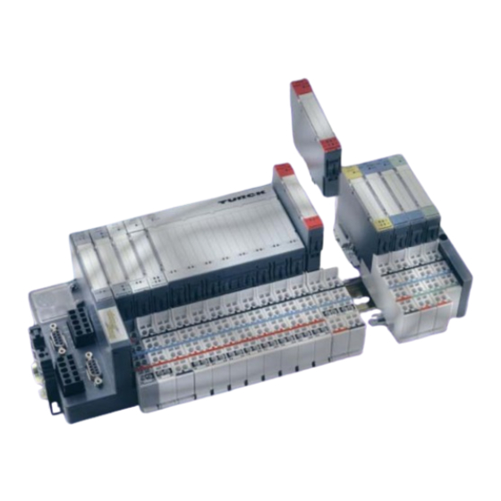
I/O-ASSISTANT. Figure 1: BL20 gateway The BL20 gateways BL20-GW-EN offer an integrated power supply unit for feeding the gateway and the connected I/O modules. It is not necessary to supply each individual module with a separate voltage. -
Page 17: Power Distribution Modules
Figure 2: Power distribution module Electronics Modules Electronics modules contain the functions of the BL20 modules (power distribution modules, digital and analog input/output modules, and technology modules). Electronics modules are plugged onto the base modules and are not directly connected to the wiring. The assignment table in the Section “Ordering Information“... - Page 18 BL20 Philosophy maintenance purposes, without having to disconnect the field wiring from the base modules. Figure 3: Electronics module in slice design Figure 4: Electronics module in block design D301034 1106 - BL20 EtherNet/IP...
-
Page 19: Base Modules
The assignment table in the Section “Ordering Information“ of the “Appendix“ shows the possible combinations of electronics and base modules. Figure 5: Base module with tension clamp connection Figure 6: Base module with screw connection D301034 1106 - BL20 EtherNet/IP... -
Page 20: End Plate
Base module in block design End Plate An end plate on the right-hand side physically completes the BL20 station. An end bracket mounted into the end plate ensures that the BL20 station remains secure on the mounting rail even when subjected to vibration. -
Page 21: End Bracket
Jumpers (QVRs) are used to bridge a connection level of a 4-wire base module. They can be used to connect potentials in relay modules (bridging the relay roots); thus considerably reducing the amount of wiring. Figure 10: Jumpers D301034 1106 - BL20 EtherNet/IP... -
Page 22: Marking Material
BL20 Philosophy Marking Material Labels: for labeling BL20 electronics modules. Markers: for colored identification of connection levels of BL20 base modules. Dekafix connector markers: for numbering the mounting slots on BL20 base modules. Figure 11: Marking material 1-10 D301034 1106 - BL20 EtherNet/IP... -
Page 23: Shield Connection, 2-Pole For Analog Modules
The 2-pole shield connection can be used to connect signal-cable shielding to the base modules of analog input and output modules. A special tension-clamp operating tool (BL20-ZBW5-2) is required to mount the shield connection onto the base module. Figure 12:... - Page 24 BL20 Philosophy 1-12 D301034 1106 - BL20 EtherNet/IP...
-
Page 25: Ethernet/Ip
– TCP (Transmission Control Protocol) ............3 Network-Topology..................4 – Transmission Media .................4 Addressing on EtherNet/IP................4 – Ethernet MAC-ID ..................4 – IP address ....................5 Network Classes ..................6 Checking the communication via "ping-signals" ........7 ARP (Address Resolution Protocol).............8 D301034 1106 - BL20 EtherNet/IP... -
Page 26: System Description
Common Industrial Protocol (CIP), the protocol that provides real-time I/O messaging and information/peer-to-peer messaging. ControlNet and DeviceNet networks also use CIP. Note For further infomation about CIP and EtherNet/IP, please contact also the user organization ODVA (www.odva.org). D301034 1106 - BL20 EtherNet/IP... -
Page 27: Ip (Internet Protocol)
Application Object Library Application Layer Application Explicit, I/O, Routing Layer Encapsulation Transport DeviceNet ControlNet and Data Link Layer Transport Transport DeviceNet ControlNet Ethernet Physical physical physical physical Layer layer layer layer ATM, Firewire, USB, Blue Tooth Ethernet/IP D301034 1106 - BL20 EtherNet/IP... -
Page 28: Network-Topology
IEEE (Institute of Electrical and Electronics Engineers, New York). The first 3 bytes of the MAC-ID contain a manufacturer identifier (Turck: 00:07:46:xx:xx:xx). The last 3 bytes can be chosen freely by the manufacturer for each device and contain a serial number. -
Page 29: Ip Address
The IP address is a 4-byte-value which contains the address of the network to which the node is connected as well as the host address in the network. The IP address of the BL20-GW-EN-IP gateway is predefined as follows: IP address: 192.168.1.×××... -
Page 30: Network Classes
1.×××.×××.×××- 126/ 2 126.×××.×××.××× 128.0.×××.××× - 191.255.×××.××× 192.0.0.××× - / 256 223.255.255.××× According to their predefined address 192.168.1.××× BL20 gate- ways are nodes on a Class C network. D301034 1106 - BL20 EtherNet/IP... -
Page 31: Checking The Communication Via "Ping-Signals
For that purpose, enter the command "ping" and the IP address of the network node to be checked. If the node answers the ping-signal, it is ready for communication and takes part in the data transfer. Figure 15: ping-signal D301034 1106 - BL20 EtherNet/IP... -
Page 32: Arp (Address Resolution Protocol)
(example: "x:\\ping 192.168.1.100"). Via the command "x:\\arp -a", the MAC-ID (00-07-46-ff-60-13) for this IP address is determined. This MAC-ID clearly identifies the network node. Figure 16: Determination of the MAC-ID of a BL20 module via D301034 1106 - BL20 EtherNet/IP... -
Page 33: Technical Features
Address setting via BootP-mode ..............12 Address setting via DHCP-mode ..............13 Address setting via PGM-mode ..............14 Addressing via PGM-DHCP ..............15 Address setting via the software "I/O-ASSISTANT" .........15 SET Button..................17 Status Indicators/Diagnostic Messages Gateway......18 Diagnostic Messages via LEDs ..............18 D301034 1106 - BL20 EtherNet/IP... -
Page 34: General
Technical Features General This chapter contains the general technical description of the BL20 gateway for Ethernet. The following technical features are indepen- dent of the implemented protocol. The chapter describes: the technical data, the connection possibili- ties, the addressing of the gateway etc. -
Page 35: Function
Function Function The gateway is the connection between the BL20 I/O-modules and the Ethernet-network. It handles the entire process data traffic between the I/O-level and the fieldbus and generates diagnostic information for higher-level nodes and the software tool I/O-ASSISTANT. D301034 1106 - BL20 EtherNet/IP... -
Page 36: Technical Data
B module bus LEDs C SET-button D rotary coding switches E Ethernet F Ethernet LEDs G power supply Gateway structure The BL20 gateway has the following structure: Figure 18: Gateway structure Fieldbus Service Controller External RAM Module bus (External) interface... - Page 37 100 mA connected field bus connection RJ45 female connector technology field bus shielding via Ethernet cable connection Isolation voltages 500 V AC (Ethernet/ service interface) 500 V DC (Ethernet/ module bus) 1000 V DC to U D301034 1106 - BL20 EtherNet/IP...
- Page 38 This device can cause radio disturbances in residential areas and in small industrial areas (residential, business and trading). In this case, the operator can be required to take appropriate measures to sup- press the disturbance at his own cost. D301034 1106 - BL20 EtherNet/IP...
-
Page 39: Connection Possibilities
The service interface is used to connect the gateway to the project planning and diagnostic software I/O-ASSISTANT. The service interface is designed as a 6 pole PS/2-connection. Two types of cables can be used to connect the service interface to a PC. D301034 1106 - BL20 EtherNet/IP... -
Page 40: Connection With I/O-Assistant-Connection Cable
(connection for male connector on PC). Figure 21: PS/2 male con- nector on the connection cable to the gateway (top view) Figure 22: 9-pole SUB-D female connector on the cable for connecting to PC (top view) D301034 1106 - BL20 EtherNet/IP... -
Page 41: Address Setting
Address Setting Address Setting The addressing of the BL20 EtherNet/IP gateway can be realized via different modes: rotary mode (manual addressing via rotary coding-switches) PGM mode (manual addressing via software) BootP mode, DHCP mode (automatic addressing via BootP/ DHCP-server at the boot-up of the gateway). -
Page 42: Default Setting Of The Gateway
Adr. × 1 Adr. × 10 : 192.168.1.254 1-254 : Static rotary : BootP : DHCP : PGM : PGM-DHCP Attention After every change of the address-mode, a voltage reset must be carried out. 3-10 D301034 1106 - BL20 EtherNet/IP... -
Page 43: Address Setting Via The Rotary-Mode
: PGM-DHCP Attention The settings carried out in the rotary-mode are not stored in the module’s EEPROM. Thus, they will get lost in case of a subsequent address-assignment via a BootP/ DHCP or PGM. D301034 1106 - BL20 EtherNet/IP 3-11... -
Page 44: Address Setting Via Bootp-Mode
BootP-server are stored in the gateway’s non-vola- tile memory. If the gateway is subsequently switched to rotary- or PGM-mode, the settings carried out via BootP (IP address, subnet mask, etc.) will be taken from the module’s EEPROM. 3-12 D301034 1106 - BL20 EtherNet/IP... -
Page 45: Address Setting Via Dhcp-Mode
In "automatic allocation", the DHCP-server assigns a permanent IP address to a client. In "dynamic allocation", DHCP assigns an IP address to a client for a limited period of time. After this time or until the client D301034 1106 - BL20 EtherNet/IP 3-13... -
Page 46: Address Setting Via Pgm-Mode
: PGM-DHCP Note In the PGM-mode, all network settings (IP address, subnet mask, etc.) are read from the module’s internal EEPROM. The settings carried out in the rotary-mode are stored in the module’s non-volatile EEPROM. 3-14 D301034 1106 - BL20 EtherNet/IP... -
Page 47: Addressing Via Pgm-Dhcp
Figure 28: Interface Ethernet The IP address as well as the subnet mask of the TURCK Ethernet gateways can be changed according to the application by using the integrated Address Tool. D301034 1106 - BL20 EtherNet/IP... - Page 48 Please observe that, if the system integrated Windows-firewall is ac- tivated, difficulties may occur during the communication between the gateway and the Address-tool. The firewall may possibly inhibit the access of the tool on Ethernet. 3-16 D301034 1106 - BL20 EtherNet/IP...
-
Page 49: Set Button
Configuration when the SET button on the gateway is pressed for approximately 10 seconds; it is also saved to the both the Temp- Required Configuration Memory and the Required Configuration Memory. The LED "GW" flashes. D301034 1106 - BL20 EtherNet/IP 3-17... -
Page 50: Status Indicators/Diagnostic Messages Gateway
LEDs via the respective configuration software Diagnostic Messages via LEDs Every BL20 gateway displays the following statuses via LEDs: 2 LEDs for module bus communication (module bus LEDs): GW and IO 2 LEDs for the Ethernet communication (fieldbus-LEDs): LNK/ ACT and MS. - Page 51 I/O-ASSISTANT I/O-ASSISTANT Force 1 Hz Force Mode. Mode. Green, Maximum number of – Check the number of flashing modules at the modules connected to 4 Hz gateway is exceeded. the gateway, dismount modules D301034 1106 - BL20 EtherNet/IP 3-19...
- Page 52 Red/ Adaptable modifica- – Check the physical green tion of the physically station for pulled or new flashing, connected station; but not planned 1 Hz data transfer possible modules. 3-20 D301034 1106 - BL20 EtherNet/IP...
- Page 53 Ethernet Traffic, flashing 10 Mbit – Green Displays an active CIP Class 1 I/O connection – Green, Gateway is ready for flashing operation – Gateway indicates error – Red, DHCP/BootP search flashing of settings D301034 1106 - BL20 EtherNet/IP 3-21...
- Page 54 Technical Features 3-22 D301034 1106 - BL20 EtherNet/IP...
-
Page 55: Implementation Of Ethernet/Ip
Implementation of EtherNet/IP The EtherNet/IP Communications Profile.......... 2 I/O Messages ....................2 Explicit Messages..................2 Communications Profile of the BL20 EtherNet/IP Gateway......3 – Point to point ...................3 – Multicast ....................3 – COS I/O Connection ................3 – Cyclic I/O Connection ................3 – UCMM .....................3 –... -
Page 56: The Ethernet/Ip Communications Profile
Consists of a service field with the most significant bit set. This is an echo of the service code in the request message with the most significant bit set. A reserved byte follows the service code, which is followed by the General Status code. D301034 1106 - BL20 EtherNet/IP... -
Page 57: Communications Profile Of The Bl20 Ethernet/Ip Gateway
The EtherNet/IP Communications Profile Communications Profile of the BL20 EtherNet/IP Gateway The EtherNet/IP gateway behaves as an EtherNet/IP Server in the network; the scanner of the higher-level controller operates as a EtherNet/IP Client. The following EtherNet/IP communications types are supported:... -
Page 58: Connected Explcit Messaging
The purpose is to transfer data in the most effi- cient manner possible. The Connection ID is a number that is associated with a communi- cation relationship. Receiving nodes decode this key to know whether they must accept the data or not. D301034 1106 - BL20 EtherNet/IP... -
Page 59: Classes And Instances Of The Ethernet/Ip-Gateway
Classes and Instances of the EtherNet/IP-Gateway Classes and Instances of the EtherNet/IP-Gateway EtherNet/IP Standard Classes The BL20 gateway supports the following EtherNet/IP Standard Classes in accordance with the CIP specification. Table 4: Class Object- Description EtherNet/IP Code Name Standard Classes... - Page 60 Provides a standard way of describing a (0×F4) device’s ports. TCP/IP Contains the device TCP/IP-related (0×F5) Interface configuration information. Object Ethernet Contains link-specific counters and (0×F6) Link Object status information for an Ethernet 802.3 communications interface. D301034 1106 - BL20 EtherNet/IP...
-
Page 61: Identity Object
Classes and Instances of the EtherNet/IP-Gateway Identity Object The following description of the Identity Object is taken from the CIP specification, Vol. 1, Rev. 2.1, by ODVA & ControlNet International Ltd. and adapted to BL20. Class Attributes Table 5: Attr. No. Attribute Name... - Page 62 DEVICE WORD See Table 7: "Device Status" (0×05) STATUS SERIAL UDINT Contains the ident-no. of the (0×06) NUMBER product (3 last bytes of the MAC-ID). PRODUCT STRUCT BL20-GW-EN-IP (0×07) NAME LENGTH USINT NAME STRING [13] D301034 1106 - BL20 EtherNet/IP...
- Page 63 Returns a predefined listing of this objects attributes. 05 (0x05) Reset Starts the Reset service for the device. 14 (0x0E) Get_Attribute_Single Returns the contents of a specified attribute. 16 (0x10) Set_Attribute_Single Modifies a single attribute. D301034 1106 - BL20 EtherNet/IP...
-
Page 64: Message Router Object
The following description of the Message Router Object is taken from the CIP specification, Vol. 1, Rev. 2.1 by ODVA & ControlNet International Ltd. and adapted to BL20. Class Attributes Table 9: Attr. No. Attribute Name... - Page 65 UINT Count of the maximum (0×02) NUMBER OF number of connections CONNEC- supported. TIONS Common Services Table 11: Service Code Class Instance Service Name Common services 01 (0x01) Get_Attribute_All 14 (0x0E) Get_Attribute_Single D301034 1106 - BL20 EtherNet/IP 4-11...
-
Page 66: Message Router Request/Response Formats
Number of 16 bit words in "Additional Additional Status". Status Additional Array of Additional status. Status USINT Response Array of Response data from request or additional Data octet error data if an error was indicated in "General Status". 4-12 D301034 1106 - BL20 EtherNet/IP... - Page 67 Only part of the expected data was transferred. Connection lost The messaging connection was lost. Service not The requested service was not imple- supported mented or was not defined for this Object Class/Instance. Invalid attribute Invalid attribute data detected. value D301034 1106 - BL20 EtherNet/IP 4-13...
- Page 68 The service did not supply enough data data to perform the specified opera- tion. Attribute not The attribute specified in the request supported is not supported. Too much data The service supplied more data than expected. 4-14 D301034 1106 - BL20 EtherNet/IP...
- Page 69 Invalid attribute The service is returning the list of value list attributes supplied with status informa- tion for those attributes that were invalid. Embedded An embedded service resulted in an service error error. D301034 1106 - BL20 EtherNet/IP 4-15...
- Page 70 Key Failure in The Key Segment that was included as path the first segment in the path does not match the destination module. The object specific status shall indicate which part of the key check failed. 4-16 D301034 1106 - BL20 EtherNet/IP...
- Page 71 Object Class specific errors. service errors Use of this range should only be performed when none of the Error Codes presented in this table accu- rately reflect the error that was encoun- tered. D301034 1106 - BL20 EtherNet/IP 4-17...
-
Page 72: Assembly Object
The following description of the Assembly Object is taken from the CIP specification, Vol. 1, Rev. 2.1 by ODVA & ControlNet Interna- tional Ltd. and adapted to BL20. Class Attributes Table 15: Attr. -
Page 73: Connection Manager Object
The following description of the Connection Manager Object is taken from the CIP specification, Vol. 1, Rev. 2.1 by ODVA & ControlNet International Ltd. and adapted to BL20. Common Services Table 18: Service Code Class Instance Service Name... -
Page 74: Port Object
Implementation of EtherNet/IP Port Object The following description of the Port Object is taken from the CIP specification, Vol. 1, Rev. 2.1 by ODVA & ControlNet International Ltd. and adapted to BL20. Class Attributes Attr. No. Attribute Name Get/ Type... - Page 75 Classes and Instances of the EtherNet/IP-Gateway Common Services Table 21: Service Code Class Instance Service Name Common services 01 (0x01) Get_Attribute_All 14 (0x0E) Get_Attribute_Single D301034 1106 - BL20 EtherNet/IP 4-21...
-
Page 76: Tcp/Ip Interface Object
Implementation of EtherNet/IP TCP/IP Interface Object The following description of the TCP/IP Interface Object is taken from the CIP specification, Vol. 2, Rev. 1.1 and adapted to BL20. Class Attributes Attr. No. Attribute Name Get/ Type Value Table 22: Class attributes 1 (0×01) - Page 77 GATEWAY UDINT 0 = Default gateway IP ADDRESS address configured NAME UDINT 0 = no name server address SERVER configured NAME UDINT 0 = no secondary name SERVER 2 server address config- ured D301034 1106 - BL20 EtherNet/IP 4-23...
- Page 78 STRING 0 = no Host Name configured (0×06) NAME (see Page 4-28) Common Services Table 24: Service Code Class Instance Service Name Common services 01 (0x01) Get_Attribute_All 02 (0x02) Set_Attribute_All 14 (0x0E) Get_Attribute_Single 16 (0×10) Set_Attribute_Single 4-24 D301034 1106 - BL20 EtherNet/IP...
- Page 79 BOOTP. DNS Client The device is capable of resolving host names by querying a DNS server. DHCP Client The device is capable of obtaining its network configuration via DHCP. D301034 1106 - BL20 EtherNet/IP 4-25...
- Page 80 0 = The device shall use the interface configuration values previously stored (for example, in non-vola- tile memory or via hardware switches, etc). 1 to 3 = reserved DNS Enable Always 0. 5-31 Reserved Set to 0. 4-26 D301034 1106 - BL20 EtherNet/IP...
- Page 81 Configuration attribute components are all zeros until the BOOTP or DHCP reply is received. Upon receipt of the BOOTP or DHCP reply, the Interface Config- uration attribute shows the configuration obtained via BOOTP/ DHCP. D301034 1106 - BL20 EtherNet/IP 4-27...
- Page 82 DHCP enabled stored config. valid Waiting configuration Set_Attributes BOOTP/DHCP request received response received Applying Status = configuration 0×00000000 Configuration applied TCP/IP network Change interface interface configured configuration Status = 0×00000001 4-28 D301034 1106 - BL20 EtherNet/IP...
-
Page 83: Ethernet Link Object
Ethernet Link Object The following description of the Ethernet Link Object is taken from the CIP specification, Vol. 2, Rev. 1.1 by ODVA & ControlNet Inter- national Ltd. and adapted to BL20. Class Attributes Table 28: Attr. No. Attribute Name... - Page 84 Using default values for speed and duplex (10Mbps/ half duplex). 2 = Auto negotiation failed but detected speed (default: half duplex). 3 = Successfully negotiated speed and duplex. 4 = Auto-negotiation not attempted. Forced speed and duplex. 4-30 D301034 1106 - BL20 EtherNet/IP...
- Page 85 0 = interface detects no local ware Fault hardware fault 1 = a local hardware fault is detected Common Services Table 31: Service Code Class Instance Service Name Common services 01 (0x01) Get_Attribute_All 14 (0x0E) Get_Attribute_Single 76 (0×4C) Enetlink_Get_and_Clear D301034 1106 - BL20 EtherNet/IP 4-31...
-
Page 86: Vsc-Vendor Specific Classes
Implementation of EtherNet/IP VSC-Vendor Specific Classes In addition to supporting the above named CIP Standard Classes, the BL20 gateway for EtherNet/IP supports the below vendor specific classes. It is possible to gain read (G= Get) and/or write (S= Set) access to... -
Page 87: Class Instances Of The Vsc
# OF USINT Contains the number of (0×66) INSTANCES Object Instances created in this class. MAX CLASS USINT Contains the number of the (0×67) ATTRIBUTE last Class Attribute to be implemented. D301034 1106 - BL20 EtherNet/IP 4-33... -
Page 88: Gateway Class (Vsc 100)
Implementation of EtherNet/IP Gateway Class (VSC 100) The Gateway Class contains all the parameters of the BL20 system and the gateway. Class Instance Note Please refer to paragraph Class Instances of the VSC, Page 4-33, for the description of the class instances for VSC. - Page 89 Bit 04: reserved Warnings Bit 03: "I/O Cfg Modified Warning" Bit 02: reserved Bit 01: reserved Bit 00: "I/O Diags Active Warning" At least one I/O- module sends active diag- nosics. D301034 1106 - BL20 EtherNet/IP 4-35...
- Page 90 Offers slot-related informa- tion. Bit 7 = module missing Bit 6 = false module plugged DWORD DIAG: Contains the module diag- nostic information. Module diagnostic bits that are not used are indicated by a "0". 4-36 D301034 1106 - BL20 EtherNet/IP...
-
Page 91: Application Example: Bl20 Gateway At An Allen Bradley Plc
Application Example: BL20 Gateway at an Allen Bradley PLC General ....................2 Prerequisites for this example ..............2 – Example station ..................3 Network configuration ............... 4 Changing the IP address of a PC/ network interface card ....5 Changing the IP address in Windows 2000/ Windows XP......5 Changing the IP address in Windows NT............7... -
Page 92: General
Application Example: BL20 Gateway at an Allen Bradley PLC General The following example shows detailed information about the connection of a BL20 station for EtherNet/IP to an Allen Bradley PLC. Prerequisites for this example In order to configure BL20 devices and to build up communications with the Allen Bradley ControlLogix PLC over EtherNet/IP, the following software tools and hardware devices are necessary. -
Page 93: Example Station
BL20-4DI-24VDC-P 4 bits bit by bit empty slot BL20-1AI-U(-10/0...+10VDC) 1 word word by word BL20-2AO-I(0/4...20MA) 2 words word by word BL20-4DI-24VDC-P 4 bits bit by bit BL20-1SSI 4 words 4 words word by word D301034 1106 - BL20 EtherNet/IP... -
Page 94: Network Configuration
The BL20 gateways are delivered with the IP address 192.168.1.1. Note In order to build up the communication between the BL20 gateway and a PLC/ PC or a network interface card, both devices have to be hosts in the same network. -
Page 95: Changing The Ip Address In Windows 2000/ Windows Xp
"Local Area Connection Properties" via the button "Properties" in the dialog "Local Area Connection Status". 2 Mark "Internet Protocol (TCP/IP)" and press the "Properties"- button to open the dialog "Internet Protocol (TCP/IP) Proper- ties". Figure 32: Local Area Connection Properties D301034 1106 - BL20 EtherNet/IP... - Page 96 Application Example: BL20 Gateway at an Allen Bradley PLC 3 Activate "Use the following IP address" and assign an IP address of the network mentioned above to the PC/ Network interface card (see the following figure). Figure 33: Changing the PC’s...
-
Page 97: Changing The Ip Address In Windows Nt
Changing the IP address in Windows NT 1 Open the folder "Network" in the Control Panel. 2 Activate TCP/IP connection in the tab "Protocols" and click the "Properties" button. Figure 34: Network configura- tion WIN NT D301034 1106 - BL20 EtherNet/IP... - Page 98 Application Example: BL20 Gateway at an Allen Bradley PLC 3 Activate "Specify IP address " and set the address as follows. Figure 35: Specify IP address D301034 1106 - BL20 EtherNet/IP...
-
Page 99: Changing The Ip Address Via I/O-Assistant
Ethernet. Please adapt your firewall settings accordingly or deacti- vate it completely (see also "Deactivating/ adapting the firewall in Windows XP", Page 5-11). The network is browsed for connected hosts which are then listed in the Address Tool. D301034 1106 - BL20 EtherNet/IP... - Page 100 Application Example: BL20 Gateway at an Allen Bradley PLC The address changing is done via "Tools → Changing IP settings...". It is now possible to change the address settings for all nodes in the list or only for the selected one.
-
Page 101: Deactivating/ Adapting The Firewall In Windows Xp
Deactivating the firewall Open the "Windows Firewall" dialog in the control panel of your PC and deactivate it as follows: Figure 39: Deactivating the Windows firewall D301034 1106 - BL20 EtherNet/IP 5-11... - Page 102 Application Example: BL20 Gateway at an Allen Bradley PLC Adapting the firewall The firewall remains active, the option "Don’t allow exceptions" it deactivated: Figure 40: Activating the Windows firewall In the "Exceptions"-tab, add the I/O-ASSISTANT to "Programs and Services". Pressing the button "Add Program..." opens the dialog "Add a Program".
- Page 103 "IOassistant.exe" from the installation directory of the software. Figure 41: "Exceptions"-tab Despite an active firewall, the I/O-ASSISTANT is now able to browse the network for hosts and the address changing via the software is possible for the connected nodes. D301034 1106 - BL20 EtherNet/IP 5-13...
-
Page 104: Address Setting At The Gateway
Application Example: BL20 Gateway at an Allen Bradley PLC Address setting at the gateway Address setting via DHCP-mode In this application example, the IP address is set via DHCP using the software tool "BootP/DHCP-Server" version 2.3.2.0 from Rockwell Automation. Figure 42:... - Page 105 Address setting at the gateway After having been connected to the network, the BL20 sends DHCP requests to the server using its MAC-ID. Figure 43: DHCP-request of BL20 gateway D301034 1106 - BL20 EtherNet/IP 5-15...
- Page 106 Application Example: BL20 Gateway at an Allen Bradley PLC A double click on the request-entry opens the "New Entry" dialog box in which an IP address can be assigned to the module’s MAC-ID. Figure 44: Setting the IP address via DHCP...
- Page 107 Address setting at the gateway The BootP/DHCP-Server sends the IP Address via BootP/DHCP to the BL20 gateway and, after a few seconds, the gateway answers with its new IP address when having stored it. Figure 45: Setting the IP address via DHCP The "Relation list"...
-
Page 108: Setting-Up Communications With The Software Tool "Rslinx
Application Example: BL20 Gateway at an Allen Bradley PLC Setting-up communications with the software tool "RSLinx" Before the EtherNet/IP network can be configured, access to EtherNet/IP must be established using the software "RSLinx" (version 2.43.01) from Rockwell Automation. The following example explains the creation of a connection via the Allen Bradley EtherNet/IP interface. - Page 109 In RSLinx, the "Autobrowse" function can be used to scan the network. All hosts in the network, which is defined by the settings of your network card, will be found. Figure 47: Scanning the EtherNet/IP network via RSWho D301034 1106 - BL20 EtherNet/IP 5-19...
-
Page 110: Configuration Of The Network In "Rslogix 5000
Application Example: BL20 Gateway at an Allen Bradley PLC Configuration of the network in "RSLogiX 5000" The EtherNet/IP hosts (PLC, EtherNet/IP interface, I/O modules) have to be configured using the software "RSLogix 5000" (in this example version 15) from Rockwell Automation. - Page 111 Open "Communications" and select the bridge. In this example this would be 1756-ENBT/A. Figure 50: Selection of the EtherNet/IP bridge Enter the "Major Revision" of your EtherNet/IP bridge and click "OK". Figure 51: Major Revision of the EtherNet/IP Bridge D301034 1106 - BL20 EtherNet/IP 5-21...
- Page 112 Application Example: BL20 Gateway at an Allen Bradley PLC In the following dialog box "New Module" enter a name for the bridge and define its IP Address (in this example 192.168.1.100). Figure 52: Configuring the EtherNet/IP Bridge In the following dialog box "Module Properties: Local..." press "OK".
-
Page 113: Configuration Of A Bl20 Station
Configuration of the network in "RSLogiX 5000" Configuration of a BL20 station Add the BL20 to the I/O configuration by using a right-click on the EtherNet/IP bridge module 1756-ENBT/A and select "New Module". Figure 53: Adding the BL20 station to the I/O... - Page 114 Application Example: BL20 Gateway at an Allen Bradley PLC Open "Communications" and select the entry "Generic Ethernet Module" to configure a BL20 gateway. Figure 54: Add generic Ethernet module Enter the necessary device information, like "Module name" and "Communication format" and define the gateway’s IP Address and...
- Page 115 Configuration of the network in "RSLogiX 5000" In the "Connection" tab set the "Requested Packet Interval" (RPI) to 10 ms, which normally should be the default setting. For BL20, the successfully tested RPI range is 5 and higher. Figure 56:...
-
Page 116: Downloading The I/O Configuration
Application Example: BL20 Gateway at an Allen Bradley PLC Downloading the I/O configuration If the configuration of the network is completed, it can be down- loaded to the controller by using for example the "Communication → Download" command. Figure 57:... - Page 117 60:), select your controller and press "Set Project Path" (see Figure 61:). Figure 59: Error message Figure 60: Communication Path Figure 61: Communication Path If the correct communication path is set, it is possible to download the configuration. D301034 1106 - BL20 EtherNet/IP 5-27...
- Page 118 Application Example: BL20 Gateway at an Allen Bradley PLC Once the I/O configuration is downloaded and the controller is in "Run" or "Remote Run" mode, the I/O-data mapping of the BL20 station is shown in the "Controller Tags": Figure 62:...
-
Page 119: Examples For I/O Data Mapping
1 control word word BL20-2AI-I(0/4...20MA) 2 words BL20-2DI-24VDC-P 2 bits BL20-2DO-24VDC-0.5A-P 2 bits BL20-2AI-THERMO-PI 2 words BL20-4DI-24VDC-P 4 bits empty slot BL20-1AI-U(-10/0...+10VDC) 1 word BL20-2AO-I(0/4...20MA) 2 words BL20-4DI-24VDC-P 4 bits BL20-1SSI 4 words 4 words D301034 1106 - BL20 EtherNet/IP 5-29... - Page 120 Application Example: BL20 Gateway at an Allen Bradley PLC According to the I/O data widths of the modules in the example station (see Table 36: „Example station”), the I/O data mapping for the example station is the following: Table 37:...
- Page 121 I/O data word in RSLogix BL20-4DI-24VDC-P – Input data BL20:I.Data [8]; Bits 0 to 3 for ch. 0 to 3. BL20-1SSI – Input data BL20:I.Data [9 - 12] – Output data BL20:O.Data [4 - 7] D301034 1106 - BL20 EtherNet/IP 5-31...
-
Page 122: Mapping Report Via I/O-Assistant
Application Example: BL20 Gateway at an Allen Bradley PLC Mapping report via I/O-ASSISTANT An EtherNet/IP I/O mapping report can be generated for each indi- vidual station by means of the software tool I/O-ASSISTANT. Figure 63: I/O mapping report in software tool... -
Page 123: Example For Process Data Access
To set the outputs "0" and "1" at module no. 2 in the example station (BL20-2DO-24VDC-0.5A-P), bit 0 bit 1 in output data word 1 (BL20:O.Data [1]) have to be set (see above Table 37: „Data mapping for the example station”). - Page 124 Application Example: BL20 Gateway at an Allen Bradley PLC 5-34 D301034 1106 - BL20 EtherNet/IP...
-
Page 125: Guidelines For Station Planning
Creating Potential Groups .................10 Protecting the Service Interface on the Gateway........11 C-Rail (Cross Connection).................11 Direct Wiring of Relay Modules ..............14 Plugging and Pulling Electronics Modules ........15 Extending an Existing Station ............16 Firmware Download ................. 17 D301034 1106 - BL20 EtherNet/IP... -
Page 126: Random Module Arrangement
BL20 modules. Maximum System Extension A BL20 station can consist of a gateway and a maximum of 74 modules in slice design (equivalent to 1 m in length of mounting rail including the end bracket and end plate). The maximum number of modules is less when using block modules (1 block module is equiv- alent to 8 modules in slice design). - Page 127 Analog outputs, BL20-2AO-I(0/4...20MA) current Analog inputs, BL20-2AO-U(-10/0...+10VDC) voltage Counter BL20-1CNT-24VDC RS232 BL20-1RS232 RS485/422 BL20-1RS232 BL20-1SSI Further limitations can be placed on the maximum possible number of BL20 modules by the use of the Power Feeding modules D301034 1106 - BL20 EtherNet/IP...
- Page 128 Guidelines for Station Planning BL20-PF-24VDC-D or BL20-PF-120/230VAC-D; these being used either for creating potential groups or by insufficient field supply. Attention Ensure that a sufficient number of Power Feeding or Bus Refreshing modules are used if the system is extended to its maximum.
-
Page 129: Power Supply
Power Supply Power Supply Module Bus Refreshing The number of BL20 modules that can be supplied by the gateway or a separate Bus Refreshing module via the internal module bus depends on the respective nominal current consumption of the indi- vidual modules on the module bus. - Page 130 Maximum permissible current via module bus: 1 500 mA The calculation shows that an additional/further Bus Refreshing module is required at the latest following the last BL20-2AO module. This Bus Refreshing module is sufficient to supply the remaining modules. Note The power requirements of the BL20 gateway is to be considered when calculating the required number of Bus Refreshing modules.
- Page 131 Power Supply The following table offers an overview of the nominal current consumption of the individual BL20 modules on the module bus: Module Supply Nominal current Table 39: Nominal current consumption consumption of the BL20 modules ≤ 430 mA Gateway...
- Page 132 “Station → Verify“. Note Bus Refreshing modules which do not supply the gateway with power are to be combined with either a BL20-P3T-SBB-B or a BL20-P4T-SBBC-B (tension clamp connection) base module or with the base modules BL20-P3S-SBB-B or BL20-P4S-SBBC-B (screw connection).
- Page 133 Attention In order to comply with radiation limit values in accordance with EN 55 011/ 2 000, the supply lines of the BL20-BR-24VDC-D mod- ule for supplying the gateway with power are to be fed through a fer- rite ring (PS416-ZBX-405). This is to be placed immediately next to the connection terminals.
-
Page 134: Creating Potential Groups
10/100 MBit – Field 2L+ 2L- supply Potential group 1 Potential group 2 – System supply Note The system can be supplied with power independent of the potential group formation described above. 6-10 D301034 1106 - BL20 EtherNet/IP... -
Page 135: Protecting The Service Interface On The Gateway
Access to the C-rail is possible with the help of base modules with a C in their designation (for example, BL20-S4T-SBCS). The corre- sponding connection level is indicated on these modules by a thick black line. - Page 136 It is permitted to load the C-rail with a maximum of 24 V. Not 230 V! The C-rail can be used as required by the application, for example, as a protective earth (PE). In this case, the PE connection of each 6-12 D301034 1106 - BL20 EtherNet/IP...
- Page 137 PE terminal, which is available as an accessory. Note For information about introducing a BL20 station into a ground ref- erence system, please read Chapter 6. Figure 69:...
-
Page 138: Direct Wiring Of Relay Modules
SBCS Cross-connecting relay module roots is achieved by the use of jumpers. The corresponding connection diagrams can be found in the manuals for the BL20 I/O modules (German: D300716, English: D300717 Direct Wiring of Relay Modules As well as the options mentioned above, relay modules can be wired directly. -
Page 139: Plugging And Pulling Electronics Modules
If the field and system supplies remain connected when electronics modules are plugged or pulled, short interruptions to the module bus communications can occur in the BL20 station. This can lead to undefined statuses of individual inputs and outputs of different modules. -
Page 140: Extending An Existing Station
Guidelines for Station Planning Extending an Existing Station Attention Please note that extensions to the station (mounting further mod- ules) should be carried out only when the station is in a voltage-free state. 6-16 D301034 1106 - BL20 EtherNet/IP... -
Page 141: Firmware Download
I/O-ASSISTANT. More information is available in the program’s online help. Attention The station should be disconnected from the fieldbus when down- loading. Firmware must be downloaded by authorized personnel only. The field level must be isolated. D301034 1106 - BL20 EtherNet/IP 6-17... - Page 142 Guidelines for Station Planning 6-18 D301034 1106 - BL20 EtherNet/IP...
-
Page 143: Guidelines For Electrical Installation
Ensuring Electromagnetic Compatibility .............6 Grounding of Inactive Metal Components ..........6 PE Connection.....................7 Earth-Free Operation...................7 Mounting Rails.....................7 Shielding of cables ................9 Potential Compensation ..............11 Switching Inductive Loads ................11 Protection against Electrostatic Discharge (ESD ........12 D301034 1106 - BL20 EtherNet/IP... -
Page 144: General Notes
DC voltage > 60 V and ≤ 400 V unshielded cables for AC voltage > 25 V and ≤ 400 V Group 3: unshielded cables for DC and AC voltages > 400 V D301034 1106 - BL20 EtherNet/IP... -
Page 145: Lightning Protection
The cables must be routed in double-grounded metal piping or in reinforced concrete cable ducts. Signal cables must be protected against overvoltage by varistors or inert-gas filled overvoltage arrestors. Varistors and overvoltage arrestors must be installed at the point where the cables enter the building. D301034 1106 - BL20 EtherNet/IP... -
Page 146: Transmission Media
(10BaseT) with shielding (STP) or without shielding (UTP). Note TURCK offers a variety of cable types for fieldbus lines as premoul- ded or bulk cables with different connectors. The ordering information for the available cable types can be found under www.turck.com. -
Page 147: Potential Relationships
All BL20 modules (gateway, Power Feeding and I/O-modules), are connected capacitively via base modules to the mounting rails. The block diagram shows the arrangement of a typical BL20 station. Figure 71: gateway I/O-module... -
Page 148: Electromagnetic Compatibility (Emc)
Ensuring Electromagnetic Compatibility The EMC of BL20 modules is guaranteed when the following basic rules are adhered to: Correct and large surface grounding of inactive metal compo- nents. -
Page 149: Pe Connection
All mounting rails must be mounted onto the mounting plate with a low impedance, over a large surface area, and must be correctly earthed. Figure 72: Mounting options A TS 35 B Mounting rail C Mounting plate D301034 1106 - BL20 EtherNet/IP... - Page 150 Remove the isolating layer from all painted, anodized or isolated metal components at the connection point. Protect the connection point against corrosion (for example with grease; caution: use only suitable grease). D301034 1106 - BL20 EtherNet/IP...
-
Page 151: Shielding Of Cables
20 cm apart) and be connected to a reference potential area. The cable shield should not be severed, but routed further within the system (for example, to the switchgear cabinet), right up to the inter- face connection. D301034 1106 - BL20 EtherNet/IP... - Page 152 A further possibility is a double-shielded cable (galvanically separat- ed), whereby the innermost shield is connected on one side and the outermost shield is connected on both sides. 7-10 D301034 1106 - BL20 EtherNet/IP...
-
Page 153: Potential Compensation
Compensation cables and data cables should be routed as close together as possible, meaning the enclosed area should be kept as small as possible. Switching Inductive Loads In the case of inductive loads, a protective circuit on the load is recommended. D301034 1106 - BL20 EtherNet/IP 7-11... -
Page 154: Protection Against Electrostatic Discharge
Protection against Electrostatic Discharge (ESD Attention Electronic modules and base modules are at risk from electrostatic discharge when disassembled. Avoid touching the bus connections with bare fingers as this can lead to ESD damage. 7-12 D301034 1106 - BL20 EtherNet/IP... - Page 155 Baud is a measure for the transmission speed of data. 1 Baud corresponds to the transmission of one bit per second (bit/s). Baud rate Unit of measurement for measuring data transmission speeds in bit/s. Bidirectional Working in both directions. D301034 1106 - BL20 EtherNet/IP...
- Page 156 Coding elements Two-piece element for the unambiguous assignment of electronic and base modules. Configuration Systematic arrangement of the I/O-modules of a station. D301034 1106 - BL20 EtherNet/IP...
- Page 157 All objects that produce, convert, transmit, distribute or utilize electrical power (e. g. conductors, cable, machines, control devices). Electromagnetic compatibility – the ability of an electrical part to operate in a specific environment without fault and without exerting a negative influence on its environment. D301034 1106 - BL20 EtherNet/IP...
- Page 158 Hexadecimal System of representing numbers in base 16 with the digits 0... 9, and further with the letters A, B, C, D, E and F. D301034 1106 - BL20 EtherNet/IP...
- Page 159 Lightning protection All measures taken to protect a system from damage due to overvoltages caused by lightning strike. Low impedance connection Connection with a low AC impedance. D301034 1106 - BL20 EtherNet/IP...
- Page 160 Potential free Galvanic isolation of the reference potentials in I/O-modules of the control and load circuits. Potential linked Electrical connection of the reference potentials in I/O-modules of the control and load circuits. D301034 1106 - BL20 EtherNet/IP...
- Page 161 Type of information transmission, by which data is transmitted bit by bit via a cable. Setting parameters Setting parameters of individual stations on the bus and their modules in the configuration software of the master. D301034 1106 - BL20 EtherNet/IP...
- Page 162 Connection of a conductive component with the grounding connection via a grounding installation. Topology Geometrical structure of a network or the circuitry arrangement. Abbreviation for User Datagram Protocol. UDP is an transport protocol for the connectionless data between Ethernet hosts. Unidirectional Working in one direction. D301034 1106 - BL20 EtherNet/IP...
- Page 163 D301034 1106 - BL20 EtherNet/IP...
- Page 164 Glossary 8-10 D301034 1106 - BL20 EtherNet/IP...
- Page 165 ....5-1 – MAC-ID ........2-4 – manufacturer identifier ....2-4 – netmask ........2-5 PE connection ....... 7-7 – network classes ......2-6 pin assignment – subnet ID ........2-5 – power supply ......3-7 D301034 1106 - BL20 EtherNet/IP...
- Page 166 – analog modules ......1-11 shielding ........7-9 symbols ......... 0-4 (Transmission Control Protocol) ..2-3 TCP/IP host ........2-5 transport, appropriate ....0-3 UCMM ........... 4-3 WIN 2000 ........5-5 WIN NT .......... 5-7 WIN XP .......... 5-5 D301034 1106 - BL20 EtherNet/IP...
- Page 167 TURCK WORLD-WIDE HEADQUARTERS GERMANY Hans Turck GmbH & Co. KG Witzlebenstraße 7 D-45472 Mülheim an der Ruhr P. O. Box 45466 Mülheim an der Ruhr Phone (+49) (208) 4952-0 (+49) (208) 4952-2 64 E-Mail more@turck.com D301034 1106 *D300782ßß0704* Subject to change without notice...
Need help?
Do you have a question about the BL20 and is the answer not in the manual?
Questions and answers