
Related Manuals for turck BL20-E-GW-EC


Summary of Contents for turck BL20-E-GW-EC
- Page 1 Your Global Automation Partner BL20-E-GW-EC ECO Gateway for EtherCAT Instructions for Use...
- Page 2 Hans Turck GmbH & Co. KG | T +49 208 4952-0 | F +49 208 4952-264 | more@turck.com | www.turck.com...
-
Page 3: Table Of Contents
Table of Contents About These Instructions Target groups Documentation concept Explanation of symbols used 1.3.1 Additional documents Feedback about these instructions Notes on the Product Product identification Scope of delivery Legal requirements Manufacturer and service For Your Safety Intended use General safety instructions EtherCAT features supported by BL20 EtherCAT according to the Modular Device Profile... - Page 4 Integration of the SWIRE-module BL20-E-1-SWIRE 7.4.1 Data image Integration of the Encoder/PWM-module BL20-E-2CNT/2PWM Integration of RFID-modules BL20-2RFID-S/-A Guidelines for station planning Hans Turck GmbH & Co. KG | T +49 208 4952-0 | F +49 208 4952-264 | more@turck.com | www.turck.com...
- Page 5 Module arrangement 8.1.1 Random module arrangement 8.1.2 Complete planning 8.1.3 Maximum system extension Power supply 8.2.1 Power supply to the gateway 8.2.2 Module bus refreshing (BL20-BR-24VDC-D) 8.2.3 Creating potential groups 8.2.4 C-rail (cross connection) 8.2.5 Direct wiring of relay modules Protecting the service interface on the gateway Plugging and pulling electronics modules Extending an existing station...
- Page 6 Hans Turck GmbH & Co. KG | T +49 208 4952-0 | F +49 208 4952-264 | more@turck.com | www.turck.com...
-
Page 7: About These Instructions
The bus-independent I/O-modules of the BL20-system as well as all bus independent information as mounting, labeling etc. are described in a separate manual. BL20 I/O-modules (Turck-documentation no.: German D300716; English D300717) In addition to that, the manual contains a short description of the I/O-ASSISTANT, the project plan-... -
Page 8: Explanation Of Symbols Used
If you have any suggestions for improving the design or if some information is missing in the doc- ument, please send your suggestions to techdoc@turck.com. Hans Turck GmbH & Co. KG | T +49 208 4952-0 | F +49 208 4952-264 | more@turck.com | www.turck.com... -
Page 9: Notes On The Product
45472 Muelheim an der Ruhr Germany Turck supports you with your projects, from initial analysis to the commissioning of your applica- tion. The Turck product database contains software tools for programming, configuration or com- missioning, data sheets and CAD files in numerous export formats. You can access the product data- base at the following address:www.turck.de/produkte... - Page 10 Notes on the Product Hans Turck GmbH & Co. KG | T +49 208 4952-0 | F +49 208 4952-264 | more@turck.com | www.turck.com...
-
Page 11: For Your Safety
The devices are only intended for use in industrial applications. The BL20 gateway BL20-E-GW-EC is part of the BL20 system. It forms the interface to an EtherCat network and forwards the data collected by the BL20 I/O modules within the BL20 station from the field to the higher-level EtherCat master. - Page 12 For Your Safety Hans Turck GmbH & Co. KG | T +49 208 4952-0 | F +49 208 4952-264 | more@turck.com | www.turck.com...
-
Page 13: Ethercat Features Supported By Bl20
EtherCAT features supported by BL20 EtherCAT according to the Modular Device Profile The EtherCAT gateway for BL20-ECO complies to the EtherCAT Modular Device Profile (MDP) according to EtherCat-standard ETG 5001. The BL20-ECO gateway for EtherCAT supports CANopen over EtherCAT (CoE). NOTE File Access over EtherCAT (FoE), Servo Profile over EtherCAT (SoE) and Ethernet over Eth- erCAT (EoE) are not be supported, yet. -
Page 14: Ethercat State Machine
SDO and PDO transfer, in- and output data valid 4.1.2 SDO services All SDO-services are integrated according to ETG 1000.5. Hans Turck GmbH & Co. KG | T +49 208 4952-0 | F +49 208 4952-264 | more@turck.com | www.turck.com... -
Page 15: Communication Area
M = mandatory O = optional C = conditional 0×1000 Device Type (0×00001389) 0×1001 Error Register, see s. p. 14 0×1008 Device Name (BL20-E-GW-EC) 0×1009 Hardware Version 0×100A Software Version 0×1018 Identity (Device identification), see s. p. 14 p. 14 0×10F3... - Page 16 For Example: „Mapping RxPDO BL20-E-4AO-U/I“ The corresponding subjects are named based on the channel count. For Example: "Output Mapping Area 2" for channel 2. Hans Turck GmbH & Co. KG | T +49 208 4952-0 | F +49 208 4952-264 | more@turck.com | www.turck.com...
- Page 17 Sync Manager Communication Type (0×1C00) This object describes the use of the Sync Manager channels. Sync Manager Channel Description Mailbox Write (EtherCAT Master view) Mailbox Read (EtherCAT-Master view) Process output data (EtherCAT-Master view) Process input data (EtherCAT-Master view) Sync Manager PDO Assign (0×1C12 and 0×1C13) The PDO Assign objects are used to describe which PDO shall be transmitted with the EtherCAT input and output data.
-
Page 18: Module Object Area (0×6000 - 0×Afff)
The EtherCAT-Master can write them to the gateway or the modules during the state transition from EtherCAT State Machine (page 12)). PRE-OP to SAFE-OP (see Hans Turck GmbH & Co. KG | T +49 208 4952-0 | F +49 208 4952-264 | more@turck.com | www.turck.com... - Page 19 EtherCAT device description file (ESI-file) (page 23). The module-parameters are defined in the Sub-index Name Data Type Details M = mandat. O = optional C = conditional 0×01 Module UNSIGNED 16 address 0×02 Type string VISIBLE STRING not supported 0×03 Name string VISIBLE STRING Contains the name of the module...
- Page 20 (0×10F3) (page 14)). This objects and the corresponding sub-objects only exists if the corresponding module supports diagnosis data. Hans Turck GmbH & Co. KG | T +49 208 4952-0 | F +49 208 4952-264 | more@turck.com | www.turck.com...
-
Page 21: Device Parameter Area
4.1.5 Device Parameter Area The device parameter area contains all parameters which belong to the EtherCAT device (gateway). The BL20 gateway supports the mandatory objects of the Modular Device Profile as well as the objects 0×F100 and 0×F200 which are mapped into the process data. Index Name Modular Device Profile, see s. - Page 22 (0×F050)as well as the list of slot-numbers Detected Address List (0×F040) are updated. 4 All other objects remain static and are only updated following a power-reset. Hans Turck GmbH & Co. KG | T +49 208 4952-0 | F +49 208 4952-264 | more@turck.com | www.turck.com...
- Page 23 Configured Module Ident List (0×F030) Contains the module ident numbers of the modules configured in the master for the BL20-station. The EtherCAT Master downloads the module ident list to the BL20-gateway and the gateway com- pares this list to the expected module configuration. Detected Module Ident In case of a difference between this list and the list in object 0×F050, see List (0×F050) (page...
- Page 24 Further information can be found in section Device Status Object (0×F100) (page 22). Device Control Object (0×F200) Not supported, yet. Reserved for future use. Hans Turck GmbH & Co. KG | T +49 208 4952-0 | F +49 208 4952-264 | more@turck.com | www.turck.com...
-
Page 25: Ethercat Device Description File (Esi-File)
Module List Handling Object (0×2000) This object serves for manual synchronization of the two module lists in the gateway (Configured Module Ident List (0×F030) Detected Module Ident List (0×F050)). Sub-index 01: theDetected Module Ident List Writing any value to this sub-index activates the copying of (0×F050) into the Configured Module Ident List... - Page 26 EtherCAT features supported by BL20 Hans Turck GmbH & Co. KG | T +49 208 4952-0 | F +49 208 4952-264 | more@turck.com | www.turck.com...
-
Page 27: Technical Features
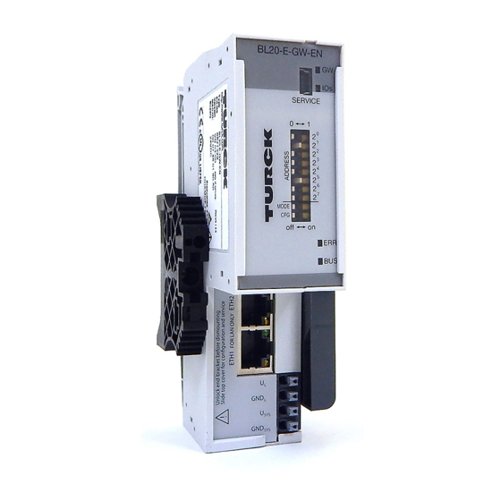
Technical features Function BL20-gateways for EtherCAT are used to connect BL20 IO modules to an EtherCAT-network. The gateway handles the entire process data exchange between the I/O-level and the fieldbus and generates diagnostic information for higher-level nodes and the software tool I/O-ASSISTANT. Technical data SERVICE GND L... -
Page 28: Block Diagram
According to EN 61 131-2 (supply of module bus nodes) 700 mA Connection technology Push-in tension clamp terminals, LSF from Weidmueller Hans Turck GmbH & Co. KG | T +49 208 4952-0 | F +49 208 4952-264 | more@turck.com | www.turck.com... - Page 29 Technical data Physical interfaces Field bus Ethernet Transmission rate 100 Mbps Passive fiber-optic-adapters can be connected Current consumption max. 100 mA Fieldbus connection technology 2 × RJ45 female connector Fieldbus shielding connection Via Ethernet cable Service interface Mini USB Address setting Not necessary for EtherCAT, address switches without function Isolation voltages...
- Page 30 (residential, business and trading). In this case, the operator can be required to take appro- priate measures to suppress the disturbance at his own cost. Hans Turck GmbH & Co. KG | T +49 208 4952-0 | F +49 208 4952-264 | more@turck.com | www.turck.com...
-
Page 31: Technical Data For The Push-In Tension Clamp Terminals
Approvals and tests Designation Approvals cULus Tests (EN 61131-2) Cold DIN IEC 68-2-1, Temperature -25 °C/185 °F, duration 96 h; device not in use Dry heat DIN IEC 68-2-2, Temperature +85 °C/185 °F, dura- tion 96 h; device not in use Damp heat, cyclic DIN IEC 68-2-30, temperature +55 °C/131 °F, dura- tion 2 cycles every 12 h;... -
Page 32: Connection Options At The Gateway
system supply (U , GND NOTE The gateway only changes to data exchange if both voltages are connected. Hans Turck GmbH & Co. KG | T +49 208 4952-0 | F +49 208 4952-264 | more@turck.com | www.turck.com... -
Page 33: Field Bus Connection Via Rj45 Sockets
5.3.2 Field bus connection via RJ45 sockets 1 = TX + 2 = TX – 3 = RX + 4 = n.c. 5 = n.c. 6 = RX – 87654321 7 = n.c. 8 = n.c. Fig. 5: RJ45 female connector Pin-no. -
Page 34: Service Interface Connection (Mini Usb Female Connector)
23)) or via the DIP-switch no. 1 at the gateway. 5.6.1 Synchronization via software using object access Module List Handling Object (0×2000) (page 23). Hans Turck GmbH & Co. KG | T +49 208 4952-0 | F +49 208 4952-264 | more@turck.com | www.turck.com... -
Page 35: Synchronization Via Hardware Using The Cfg-Switch
5.6.2 Synchronization via hardware using the CFG-switch The DIP-switches are located under the gateway’s upper label. For setting the DIP-switch pull out the label. Front view with label: SERVICE Fig. 7: Gateway-front view A DIP-switch (CFG, no. 1) for storing the station configuration Switching to ON starts the storage of the Current Configuration as the Required Configuration (Ref- erence configuration). -
Page 36: Status Indicators/Diagnostic Messages Gateway
1 Hz module list do not match but new but not planned modules. the data exchange proceeds as normal. Hans Turck GmbH & Co. KG | T +49 208 4952-0 | F +49 208 4952-264 | more@turck.com | www.turck.com... -
Page 37: Device Status Object
Status Meaning Remedy EtherCAT State Machine (page The device is in state INITIALIZA- TION green, flashing The device is in state PRE-OPER- 200 ms on/ ATIONAL 200 ms off (blinking) green, flashing The device is in state SAFE- 200 ms on/1000 ms OPERATIONAL (single flash) green... -
Page 38: Emergency Telegrams
Byte Data Error Code Error- slot-no. channel-no. reserve content Register Gateway Status information Hans Turck GmbH & Co. KG | T +49 208 4952-0 | F +49 208 4952-264 | more@turck.com | www.turck.com... -
Page 39: I/O Module Diagnosis
Data content Value Meaning Error Code 0×0000 Error-reset/no error 0×FF00 Device specific error Error Register 0×00 no error 0×81 manufacturer specific error/generic error Error register (0×1001) (page 14)) (see also slot-no. 0×0000 Gateway sends an Emergency-frame 0×0100 to slot-no. of the module which sends an emergency-frame. 0×0148 channel-no. - Page 40 Diagnostic Byte n (channel 1) Measurement value range error Only in the measurement range 4 to 20 mA open circuit Hans Turck GmbH & Co. KG | T +49 208 4952-0 | F +49 208 4952-264 | more@turck.com | www.turck.com...
- Page 41 BL20-2AI-I(0/4…20MA) Diagnosis Diagnostic Byte n (channel 1) Measurement value range error Only in the measurement range 4 to 20 mA open circuit n + 1 Measurement value range error Only in the measurement range (channel 2) 4 to 20 mA open circuit BL20-1AI-U(-10/0…+10VDC) ...
- Page 42 In this case a "short-circuit"- diag- nostic is generated. Overflow/Underflow (OUFL) reserved hardware failure Hans Turck GmbH & Co. KG | T +49 208 4952-0 | F +49 208 4952-264 | more@turck.com | www.turck.com...
- Page 43 BL20-2DO-24VDC-0.5A-P Diagnosis Diagnostic Byte overcurrent (short-circuit channel 1) overcurrent (short-circuit channel 2) BL20-2DO-24VDC-0.5A-N Diagnosis Diagnostic Byte overcurrent (short-circuit channel 1) overcurrent (short-circuit channel 2) BL20-2DO-24VDC-2A-P Diagnosis Diagnostic Byte overcurrent (short-circuit channel 1) overcurrent (short-circuit channel 2) BL20-4DO-24VDC-0.5A-P ...
- Page 44 BL20-1RS232 Diagnostic byte Diagnostic parameterization error hardware failure data flow control error frame error buffer overflow Hans Turck GmbH & Co. KG | T +49 208 4952-0 | F +49 208 4952-264 | more@turck.com | www.turck.com...
- Page 45 BL20-1RS485/422 Diagnosis Diagnostic Byte parameterization error hardware failure data flow control error (only in RS422-mode) frame error buffer overflow BL20-1SSI Diagnosis Diagnostic Byte SSI group diagnostics open circuit sensor value overflow sensor value underflow parameterization error 2020/09...
-
Page 46: Parameters Of The Modules
0 = Integer (15 bit + sign) value representation 1 = 12 bit (left-justified) Diagnostic 0 = activate 1 = deactivate Hans Turck GmbH & Co. KG | T +49 208 4952-0 | F +49 208 4952-264 | more@turck.com | www.turck.com... - Page 47 BL20-2AI-I(0/4…20MA) (1 byte per channel) Byte Parameter name Value current mode 0 = 0…20 mA 1 = 4…20 mA 0 = Integer (15 bit + sign) value representation 1 = 12 bit (left-justified) Diagnostic 0 = activate 1 = deactivate Channel 0 = activate 1 = deactivate...
- Page 48 1110 = resistance, 0…400 1111 = resistance, 0…1000 Measurement mode 0 = 2 wire 1 = 3 wire Hans Turck GmbH & Co. KG | T +49 208 4952-0 | F +49 208 4952-264 | more@turck.com | www.turck.com...
- Page 49 BL20-2AI-THERMO-PI (2 byte parameters per channel) Byte Parameter name Value Mains suppression 0 = 50 Hz 0 = 60 Hz 0 = Integer (15 bit + sign) value representation 1 = 12 bit (left-justified) Diagnostic 0 = release 1 = block Channel 0 = activate 1 = deactivate...
- Page 50 0= PV (primary variable) 1= SV (2nd variable) 2 = TV (3rd variable) 3 = QV (4th variable) Hans Turck GmbH & Co. KG | T +49 208 4952-0 | F +49 208 4952-264 | more@turck.com | www.turck.com...
- Page 51 Byte Parameter name Value HART-Variable B Defines the channel of which the HART-variable is read. channel mapping 0 = channel 1 1 = channel 2 6 + 7 variable mapping Defines which HART-variable of the connected sen- sor is mapped into the module’s process data. 0= PV (primary variable) 1= SV (2nd variable) 2 = TV (3rd variable)
- Page 52 Pt 500, -200°C…150 °C, 3-wire 011110 Pt 1000, -200°C…850 °C, 3-wire 011111 Pt 1000, -200°C…150 °C, 3-wire 100000 Ni 100, -60 °C…250 °C, 2-wire Hans Turck GmbH & Co. KG | T +49 208 4952-0 | F +49 208 4952-264 | more@turck.com | www.turck.com...
- Page 53 Byte Parameter name Value Meaning 100001 Ni 100, -60°C…150 °C, 2-wire 100010 Ni 1000, -60 °C…250 °C, 2-wire 100011 Ni 1000, -60°C…150 °C, 2-wire 100100 Ni 1000TK5000, -60 °C…250 °C, 2-wire 100101 reserved 100110 reserved 100111 reserved 101000 Ni 100, -60 °C…250 °C, 3-wire 101001 Ni 100, -60°C…150 °C, 3-wire 101010...
-
Page 54: Analog Output Modules
1 = 12 bit (left-justified) reserved Channel 0 = activate 1 = deactivate reserved to 7 Substitute value low byte Substitute value high byte Hans Turck GmbH & Co. KG | T +49 208 4952-0 | F +49 208 4952-264 | more@turck.com | www.turck.com... - Page 55 BL20-2AO-U(-10/0…+10VDC) (3 byte per channel) Byte Parameter name Value voltage mode 0 = 0…10 V 1 = -10…+10 V 0 = Integer (15 bit + sign) value representation 1 = 12 bit (left-justified) reserved 0 = activate Channel 1 = deactivate reserved to 7 Substitute value low byte...
- Page 56 0= PV (primary variable) 1= SV (2nd variable) 2 = TV (3rd variable) 3 = QV (4th variable) Hans Turck GmbH & Co. KG | T +49 208 4952-0 | F +49 208 4952-264 | more@turck.com | www.turck.com...
- Page 57 Byte Parameter name Value HART-variable D Defines the channel of which the HART-variable is read. channel mapping 0 = channel 1 1 = channel 2 6 + 7 variable mapping Defines which HART-variable of the connected sensor is mapped into the module’s process data.
-
Page 58: Technology Modules
Byte 7 contains the status or control byte. User data are represented in Bytes 0 - 5. Hans Turck GmbH & Co. KG | T +49 208 4952-0 | F +49 208 4952-264 | more@turck.com | www.turck.com... - Page 59 Byte Parameter name Value Diagnostic 0 = release – Diagnostic activated: This affects the separate fieldbus-specific diagnostic message – not the diagnosis embedded in the process input data. 1 = block Stop bits 0 = 1 bit 1 = 2 bit Parity 00 = none 01 = odd...
- Page 60 This character is used to start the transmission of data from the data terminal device if the soft- ware handshake is active. Hans Turck GmbH & Co. KG | T +49 208 4952-0 | F +49 208 4952-264 | more@turck.com | www.turck.com...
- Page 61 Byte Parameter name Value XOFF character 0 – 255 (19) only in the RS422-mode: XOFF character: This character is used to stop the transmission of data from the data terminal device if the soft- ware handshake is active. BL20-1SSI Byte Parameter name Value...
- Page 62 Data type binary coded SSI encoder sends data in binary code GRAY coded SSI encoder sends data in GRAY code Hans Turck GmbH & Co. KG | T +49 208 4952-0 | F +49 208 4952-264 | more@turck.com | www.turck.com...
- Page 63 BL20-E-1SWIRE Bit 7 Bit 6 Bit 5 Bit 4 Bit 3 Bit 2 Bit 1 Bit 0 Byte 1 reserved free free configu- Disable free ration Byte 2 free AUXERR INFO INFO INFO Byte 3 reserved Byte 4 reserved (life guarding time until version VN 01-03) Byte 5 DIAG DIAG...
- Page 64 0 = active Group diagnostics is activated 1 = inactive Group diagnostics is not activated Hans Turck GmbH & Co. KG | T +49 208 4952-0 | F +49 208 4952-264 | more@turck.com | www.turck.com...
- Page 65 TYPE setting for the LIN slave at position x on the SWIRE bus slave x 0x20 SWIRE-DIL-MTB (: 0xFF) 0xFF Basic setting (no slave) BL20-E-2CNT-2PWM (see separate manual for the module, D301224, „BL20 – I/O-MODULES BL20-E-2CNT-2PWM“, chapter 2) BL20-2RFID-S (see RFID-documentation www.turck.de) 2020/09...
- Page 66 Technical features Hans Turck GmbH & Co. KG | T +49 208 4952-0 | F +49 208 4952-264 | more@turck.com | www.turck.com...
-
Page 67: Connection Of The Ethercat-Gateway To The Twincat Soft-Plc
The integrated Soft-PLC (runtime system) is used as PLC Used software TwinCAT, V2.11 – TwinCAT System Manager – TwinCAT PLC Control Used hardware Bl20-station for EtherCAT – BL20-E-GW-EC, FW-version 1.0.0.0 – I/O-modules – Example station Module Data width Process input Process output BL20-E-GW-EC BL20-2DI-24VDC-P 2 Bit... -
Page 68: Adding A Device Specific *.Xml-File
In order to enable an xml-based configuration of the devices, the device-specific *.xml-file (for the BL20-gateway "BL20-E-GW-EC.xml") has to be copied to the installation directory of TwinCAT. Path: x:\TwinCAT\Io\EtherCAT Hans Turck GmbH & Co. KG | T +49 208 4952-0 | F +49 208 4952-264 | more@turck.com | www.turck.com... -
Page 69: Hardware Configuration In The Twincat System Manager
6.1.2 Hardware configuration in the TwinCAT System Manager 1 Open the "TwinCAT System Manager“ and create a new project. 2 Add an EtherCAT-interface to the I/O configuration. Fig. 8: Adding an EtherCAT-interface 3 In order to establish communication between your PC and the EtherCAT-network, an EtherCAT-driver for the network card is needed. - Page 70 7 Confirm the dialog box for reloading the devices with "OK". Fig. 10: Scanning the EtherCAT-network 8 The EtherCAT-nodes are now read in and added automatically to the I/O-Configuration. Hans Turck GmbH & Co. KG | T +49 208 4952-0 | F +49 208 4952-264 | more@turck.com | www.turck.com...
- Page 71 9 If the *.xml-file has been installed as described in Adding a device specific *.xml-file (page 66), the BL20-station is read in as follows. Fig. 11: BL20-station with *.xml-file 2019/09...
- Page 72 15)): – analog input modules – analog output Modules – technology modules – digital input modules – digital output modules Hans Turck GmbH & Co. KG | T +49 208 4952-0 | F +49 208 4952-264 | more@turck.com | www.turck.com...
-
Page 73: Parameterization Of Bl20 I/O-Modules
6.1.3 Parameterization of BL20 I/O-modules The parameterization of the I/O-modules in the BL20-station is done in the register-tab "CoE-Online" of the BL20-gateway. 1 In the module-specific parameter-object, open the parameter entry via double-click and set the parameter to the desired value. Fig. -
Page 74: Programming The Soft-Plc
Fig. 14: Select runtime system 3 Programming the Soft-PLC is done in the register-tab "POUs". Fig. 15: Program in TwinCAT-PLC Control Hans Turck GmbH & Co. KG | T +49 208 4952-0 | F +49 208 4952-264 | more@turck.com | www.turck.com... - Page 75 4 Program variables which are to be mapped to the hardware-configuration in the "TwinCAT Sys- tem Manager“ have to be defined as "global variables". Fig. 16: Definition of the Global Variables 5 Build and store the program, log-in and start the PLC for example via the TwinCAT-symbol in the task bar of your PC.
- Page 76 Connection of the EtherCAT-gateway to the TwinCAT Soft-PLC 6 The TwinCAT-system has to be started as well. Fig. 18: Starting the system Hans Turck GmbH & Co. KG | T +49 208 4952-0 | F +49 208 4952-264 | more@turck.com | www.turck.com...
-
Page 77: Connection" Of Hardware And Program
6.1.5 "Connection" of hardware and program 1 Add the PLC-project from the "TwinCAT System Control" to the "PLC-Configuration" in the "TwinCAT System Manager“. Fig. 19: Adding the PLC-program to the hardware-configuration. 2019/09... - Page 78 2 The global variables from the PLC-program are listed in the configuration and can now be linked to the inputs and outputs of the hardware. Fig. 20: Variables from PLC-program Hans Turck GmbH & Co. KG | T +49 208 4952-0 | F +49 208 4952-264 | more@turck.com | www.turck.com...
- Page 79 3 Define the process data which have to be linked and link the hardware to the variables using „right-click Change Single Links or Change Multi Link and define the respective program vari- able. Fig. 21: Linking of variables 2019/09...
- Page 80 TwinCAT allows a graphical representation of the variable mappings. 1 Create the mappings to show the graphical mappings. Fig. 22: Generate Mappings Hans Turck GmbH & Co. KG | T +49 208 4952-0 | F +49 208 4952-264 | more@turck.com | www.turck.com...
-
Page 81: Process Data Exchange
6.1.6 Process data exchange 1 The actual I/O-configuration is downloaded to the gateway using the "activate configuration"- button. Fig. 23: Activate I/O-configuration 2 TwinCAT is automatically restarted in Run mode. 2019/09... - Page 82 3 Open the monitoring of the process data using the "View Show Online Data"-command. Fig. 24: Monitoring of process data Hans Turck GmbH & Co. KG | T +49 208 4952-0 | F +49 208 4952-264 | more@turck.com | www.turck.com...
-
Page 83: Diagnosis In Twincat
6.1.7 Diagnosis in TwinCAT Diagnosis messages of the gateway and the I/O-modules are shown in the "Diag History" of the BL20-Gateway. Fig. 25: Diag History The sending of diagnosis messages and Emergencies can be en- or respectively disabled via the "Advanced"-button in the "Diag History"-dialog box. - Page 84 Further information about the structure of emergencies can be found in section Emergency telegrams (page 36). Fig. 27: Emergencies in TwinCAT Hans Turck GmbH & Co. KG | T +49 208 4952-0 | F +49 208 4952-264 | more@turck.com | www.turck.com...
-
Page 85: Install Ethercat-Driver
6.1.8 Install EtherCAT-driver 1 Search your system for EtherCAT-Real Time compatible network interface cards. 2 Open the dialog box "Installation of TwinCAT RT-Ethernet Adapters" via the "Compatible device"-button in the register-tab "Adapter" of the EtherCAT-device. 3 Select the network interface card to be used and install the EtherCAT-driver via the "Install"-but- ton. - Page 86 Connection of the EtherCAT-gateway to the TwinCAT Soft-PLC Hans Turck GmbH & Co. KG | T +49 208 4952-0 | F +49 208 4952-264 | more@turck.com | www.turck.com...
-
Page 87: Integration Of The Technology Modules
Integration of the technology modules Integration of the RS232-module 7.1.1 Data image Process input data (PZDE) Process input data is data from the connected field device that is transmitted via the BL20-1RS232 module to the PLC. The BL20-1RS232-module sends the data, received by the device, into a 128- byte receive-buffer. - Page 88 Errors in this sequence show the loss of data segments. RX_BYTE_CNT Number of the valid bytes in this data segment. Hans Turck GmbH & Co. KG | T +49 208 4952-0 | F +49 208 4952-264 | more@turck.com | www.turck.com...
- Page 89 Process output data (PZDA) Process output data are data which are sent from the PLC via the gateway and the BL20-1RS232- module to a connected field device. The data received from the PLC are loaded into the 64-bit transmit-buffer in the BL20-1RS232-mod- ule.
- Page 90 Number of the valid bytes in this data segment. In EtherCAT, the data seg- ments contain a maximum number of 6 bytes of user data. Hans Turck GmbH & Co. KG | T +49 208 4952-0 | F +49 208 4952-264 | more@turck.com | www.turck.com...
-
Page 91: Integration Of The Rs485/422-Module
Integration of the RS485/422-module 7.2.1 Data image Process input data (PZDE) The BL××-1RS485/422-module sends the data, received by the device, into a 128-byte receive-buf- fer. The module then transmits the data segmented via the module bus and the gateway to the SPS. The transmission is realized in a 8-byte format which is structured as follows: 6 bytes are used to contain the user data. - Page 92 A request with TXBUF FLUSH = 1 will be ignored. If TXBUF FLUSH = 1, a falling edge 1 0 at STATRES clears the transmit buf- fer. Hans Turck GmbH & Co. KG | T +49 208 4952-0 | F +49 208 4952-264 | more@turck.com | www.turck.com...
- Page 93 Designation Value Description STATRES 0 - 1 This bit is set to reset the STAT bit in the process input data. With the change from 1 to 0 the STAT bit is reset (from 0 to 1). The clearing of the receive and transmit buffer by RXBUF FLUSH/TXBUF FLUSH is possi- ble.
-
Page 94: Integration Of The Ssi-Module
FLAG describes a retentive flag that is set in the event of a particular event. The bit concerned retains the value until it is reset. Fig. 33: Process input data Hans Turck GmbH & Co. KG | T +49 208 4952-0 | F +49 208 4952-264 | more@turck.com | www.turck.com... - Page 95 Meaning of the data bits (process input) Designation Value Description REG_RD_DATA 0… 2 Content of the register to be read if REG_RD_ABORT=0. If REG_RD_ABORT =1, then REG_RD_DATA=0. REG_RD_ The reading of the register defined in REG_RD_ADR has been ABORT accepted and executed. The content of the register can be found in the user data (REG_RD_DATA, byte 0-3).
- Page 96 The parameter set of the module has been accepted. Operation of the module is not possible with the present param- eter set. Hans Turck GmbH & Co. KG | T +49 208 4952-0 | F +49 208 4952-264 | more@turck.com | www.turck.com...
- Page 97 Designation Value Description STS_UFLW A comparison of the register contents has produced the following result: (REG_SSI_POS) (REG_LOWER_LIMIT) A comparison of the register contents has produced the following result: (REG_SSI_POS) < (REG_LOWER_LIMIT) STS_OFLW A comparison of the register contents has produced the following result: (REG_SSI_POS) ...
- Page 98 Request to overwrite the content of the register with address REG_WR_ADR with REG_WR_DATA. REG_WR_ADR 0…63 Address of the register, which has to be written with REG_WR_- DATA. Hans Turck GmbH & Co. KG | T +49 208 4952-0 | F +49 208 4952-264 | more@turck.com | www.turck.com...
- Page 99 Designation Value Description CLR_CMP2 Default status, i.e. no reset of FLAG_CMP2 active. Reset of FLAG_CMP2 active. EN_CMP2 Default status, i.e. the data bits REL_CMP2, STS_CMP2 and FLAG_CMP2 always have the value 0, irrespective of the actual SSI encoder value. Comparison active, i.e. the data bits REL_CMP2, STS_CMP2 and FLAG_CMP2 always have a value based on the result of the com- parison with the SSI encoder value.
-
Page 100: Integration Of The Swire-Module Bl20-E-1-Swire
Contactor coil is switched off Contactor coil is switched on Hans Turck GmbH & Co. KG | T +49 208 4952-0 | F +49 208 4952-264 | more@turck.com | www.turck.com... - Page 101 Design. Status Comment PKZSTx Switch status, PKZ x The motor-protective circuit breaker is off or has tripped The motor-protective circuit breaker is switched on Communication error, slave x Setting the NDDIAG parameter copies the slave diagnostics message (input byte 1/bit 3) to the feed-back interface. The information is provided as status information in the PLC for the user.
- Page 102 SOx is transferred as the switch status of the contactor coil from the SWIRE bus master to the appropriate SWIRE bus slave. Contactor not switched on Contactor switched on Hans Turck GmbH & Co. KG | T +49 208 4952-0 | F +49 208 4952-264 | more@turck.com | www.turck.com...
- Page 103 Diagnostics Bit 7 Bit 6 Bit 5 Bit 4 Bit 3 Bit 2 Bit 1 Bit 0 Byte 1 GENER- free free free SWERR Byte 2 free free free free AUXERR field Byte 3 Byte 4 Slave diagnostics bit field Byte 5 Byte 6 PKZ field...
- Page 104 Contactor supply voltage is o.k. (> 20 VDC) or diagnostics function has been deactivated via this parameter. under voltage Contactor supply voltage is not o.k. (< 18 VDC). Hans Turck GmbH & Co. KG | T +49 208 4952-0 | F +49 208 4952-264 | more@turck.com | www.turck.com...
- Page 105 Design. Value Meaning Byte 3.4 Device configuration, slave x Info field for the individual indication of a configuration error as error message. If the TYP INFO parameter has been set for single diagnostics, this bit field indicates the error, as soon as the ACTUAL configuration of the slave was not accepted and is therefore not enabled for data exchange.
- Page 106 Slaves that do not match the set configuration are inac- tive. Hans Turck GmbH & Co. KG | T +49 208 4952-0 | F +49 208 4952-264 | more@turck.com | www.turck.com...
- Page 107 Parameter name Value Moeller conformance (from version VN 01-04) Behavior of the BL20-E-1SWIRE in accordance with SWIRE Conformance criteria. 0 = inactive Default behavior 1 = active The BL20-E-1SWIRE master responds according to the Moeller SWIRE Conformance criteria. For detailed information please read the manual for the IO-modules (D300717).
-
Page 108: Integration Of The Encoder/Pwm-Module Bl20-E-2Cnt/2Pwm
Detailed information about the process image of the module can be found in separate manual, D301224, „BL20 – I/O-MODULES BL20-E-2CNT-2PWM“, chapter 2) Integration of RFID-modules BL20-2RFID-S/-A BL20-2RFID-S and BL20-2RFID-A (see RFID-documentation under www.turck.de) Hans Turck GmbH & Co. KG | T +49 208 4952-0 | F +49 208 4952-264 | more@turck.com | www.turck.com... -
Page 109: Guidelines For Station Planning
Guidelines for station planning Module arrangement 8.1.1 Random module arrangement The arrangement of the I/O-modules within a BL20 station can basically be chosen at will. Nevertheless, it can be useful with some applications to group certain modules together. NOTE A mixed usage of gateways of the BL20 ECO and the BL20 standard product line and I/O modules of both product lines (base modules with tension clamp terminals) is possible without any problems. -
Page 110: Maximum System Extension
41 mA BL20-2AI-I(0/4…20MA) 35 mA BL20-1AI-U(-10/0…+10VDC) 41 mA BL20-2AI-U(-10/0…+10VDC) 35 mA BL20-2AI-PT/NI-2/3 45 mA BL20-2AI-THERMO-PI 45 mA BL20-4AI-U/I 30 mA Hans Turck GmbH & Co. KG | T +49 208 4952-0 | F +49 208 4952-264 | more@turck.com | www.turck.com... - Page 111 Module Nominal current consumption at the module bus BL20-E-8AI-U/I-4AI-PT/NI 50 mA BL20-2DO-24VDC-0.5A-P 32 mA BL20-2DO-24VDC-0.5A-N 32 mA BL20-2DO-24VDC-2A-P 33 mA BL20-2DO-120/230VAC-0.5A 35 mA BL20-4DO-24VDC-0.5A-P 30 mA 5 mA BL20-E-8DO-24VDC-0.5A-P BL20-E-16DO-24VDC-0.5A-P 25 mA BL20-E-16DO-24VDC-0.5A-N 25 mA BL20-16DO-24VDC-0.5A-P 120 mA BL20-32DO-24VDC-0.5A-P 30 mA BL20-1AO-I(0/4…20MA) 39 mA BL20-2AO-I(0/4…20MA)
-
Page 112: Power Supply
Ensure that the correct base modules are planned for when using Bus Refreshing modules. NOTE The system can be supplied with power independent of the potential group formation. Hans Turck GmbH & Co. KG | T +49 208 4952-0 | F +49 208 4952-264 | more@turck.com | www.turck.com... -
Page 113: C-Rail (Cross Connection)
When using a digital input module for 120/230 V AC, it should be ensured that a potential group is created in conjunction with the Power Feeding module BL20-PF-120/230VAC-D. NOTICE Common potential of 24 VDC and 230 VAC field supply Destruction of electronic †... - Page 114 Only then can the C-rail serve as PE again. Hans Turck GmbH & Co. KG | T +49 208 4952-0 | F +49 208 4952-264 | more@turck.com | www.turck.com...
-
Page 115: Direct Wiring Of Relay Modules
Fig. 39: Using the C-rail as protective earth and for the power supply with relay modules Cross-connecting relay module roots is achieved by the use of jumpers. The corresponding wiring diagram including the jumpers can be found the manuals for BL20 I/O modules (German: D300716, English: D300717). -
Page 116: Plugging And Pulling Electronics Modules
Damage of the firmware † Disconnect the station from the modules bus before the download. † Disconnect the field side. Hans Turck GmbH & Co. KG | T +49 208 4952-0 | F +49 208 4952-264 | more@turck.com | www.turck.com... -
Page 117: Guidelines For Electrical Installation
Guidelines for Electrical Installation General notes 9.1.1 General Cables should be grouped together, for example: signal cables, data cables, heavy current cables, power supply cables. Heavy current cables and signal or data cables should always be routed in separate cable ducts or bundles. -
Page 118: Lightning Protection
All BL20 modules (gateway, Power Feeding and I/O-modules), are connected capacitively via base modules to the mounting rails. Hans Turck GmbH & Co. KG | T +49 208 4952-0 | F +49 208 4952-264 | more@turck.com | www.turck.com... -
Page 119: Electromagnetic Compatibility
The block diagram shows the arrangement of a typical BL20 station with Ethernet gateway. Service Module bus Switch Logik Logik Logik Logik 24 V Eth1 Eth2 Gateway Output Intput Output Power Output Refreshing Feeding Fig. 40: Block diagram of a BL20 station with EtherCAT- gateway Electromagnetic compatibility (EMC BL20 products comply in full with the requirements pertaining to EMC regulations. -
Page 120: Pe Connection
Mount the mounting rails over a large surface area and with a low impedance to the support system using screws or rivets. Remove the isolating layer from all painted, anodized or isolated metal com- Hans Turck GmbH & Co. KG | T +49 208 4952-0 | F +49 208 4952-264 | more@turck.com | www.turck.com... -
Page 121: Shielding Of Cables
ponents at the connection point. Protect the connection point against corrosion (for example with grease; caution: use only suitable grease). 9.3.6 Shielding of cables Shielding is used to prevent interference from voltages and the radiation of interference fields by cables. Therefore, use only shielded cables with shielding braids made from good conducting mate- rials (copper or aluminum) with a minimum degree of coverage of 80%. -
Page 122: Potential Compensation
NOTICE Exposed metal contacts Material damage due to electrostatic discharge † Avoid to touch the metallic contacts with bare hands Hans Turck GmbH & Co. KG | T +49 208 4952-0 | F +49 208 4952-264 | more@turck.com | www.turck.com... -
Page 123: Bl20-Approvals For Zone 2/Division
10 BL20-Approvals for Zone 2/Division 2 NOTE The Zone 2 - approval certificates for BL20 can be found in a separate manual for approvals D301255 at www.turck.de. 2020/09... - Page 124 BL20-Approvals for Zone 2/Division 2 Hans Turck GmbH & Co. KG | T +49 208 4952-0 | F +49 208 4952-264 | more@turck.com | www.turck.com...
-
Page 125: 11 Appendix
11 Appendix 11.1 Identifiers of BL20-modules Each module is identified by the gateway using a unique identifier. Module Identifier Digital input modules BL20-2DI-24VDC-P 0x210020xx BL20-2DI-24VDC-N 0x220020xx BL20-2DI-120/230VAC 0x230020xx BL20-4DI-24VDC-P 0x410030xx BL20-4DI-24VDC-N 0x420030xx BL20-4DI-NAMUR 0x015640xx BL20-E-8DI-24VDC-P 0x610040xx BL20-16DI-24VDC-P 0x810050xx BL20-E-16DI-24VDC-P 0x820050xx BL20-E-16DI-24VDC-N 0x830050xx BL20-32DI-24VDC-P... - Page 126 0x017BCCxx BL20-2RFID-A 0x017977xx BL20-2RFID-S 0x2179CCxx BL20-E-4IOL 0x409BBBxx BL20-E-4IOL-10 0x409DDDxx Power distribution modules BL20-BR-24VDC-D 0x013000xx BL20-BR-24VDC-RED 0x440030xx BL20-PF-24VDC-D 0x023000xx BL20-PF-120/230VAC-D 0x053000xx Hans Turck GmbH & Co. KG | T +49 208 4952-0 | F +49 208 4952-264 | more@turck.com | www.turck.com...
- Page 127 Over 30 subsidiaries and over 60 representations worldwide! D301260 | 2020/09 *D301260* www.turck.com...
Need help?
Do you have a question about the BL20-E-GW-EC and is the answer not in the manual?
Questions and answers