turck BL20 User Manual
Eco gateway
for
ethernet/ip
Hide thumbs
Also See for BL20:
- Instructions for use manual (537 pages) ,
- User manual (461 pages) ,
- Manual (175 pages)
Table of Contents
Advertisement
Quick Links
Download this manual
See also:
User Manual
Advertisement
Chapters
Table of Contents

Subscribe to Our Youtube Channel
Related Manuals for turck BL20


Summary of Contents for turck BL20
-
Page 1: User Manual
BL20 – USER MANUAL ECO GATEWAY EtherNet/IP™... - Page 2 No part of this manual may be reproduced in any form (printed, photocopy, microfilm or any other process) or processed, duplicated or distributed by means of electronic systems without written permission of Hans Turck GmbH & Co. KG, Muelheim an der Ruhr. Subject to alterations without notice...
- Page 3 Warning! Before commencing the installation Disconnect the power supply of the device. Ensure that devices cannot be accidentally restarted. Verify isolation from the supply. Earth and short circuit. Cover or enclose neighboring units that are live. Follow the engineering instructions of the device concerned. Only suitably qualified personnel in accordance with EN 50 110-1/-2 (VDE 0 105 Part 100) may work on this device/system.
-
Page 5: Table Of Contents
Technical data for the push-in tension clamp terminals ......................4-8 Connection options at the gateway.......................4-9 4.4.1 Voltage supply......................................4-9 4.4.2 Field bus connection via Ethernet-switch .............................4-9 4.4.3 Service interface connection (mini USB female connector) ....................4-9 Address setting............................. 4-11 4.5.1 Default-settings for the gateway..............................4-11 D301174 1211 - BL20-ECO EtherNet/IP... - Page 6 5.1.1 I/O Messages ......................................5-3 5.1.2 Explicit Messages ....................................5-3 5.1.3 Communications profile of the BL20 EtherNet/IP gateway ....................5-3 Classes and instances of the EtherNet/IP-gateway ..................5-5 5.2.1 EtherNet/IP standard classes ................................5-5 5.2.2 Identity Object (0×01) ..................................5-6 5.2.3...
- Page 7 5.3.18 Analog versatile module class (VSC118) ............................. 5-88 5.3.19 SWIRE module class (VSC121)................................. 5-91 5.3.20 RFID-S module class (VSC124) ................................ 5-96 Application example: BL20 gateway with an Allen Bradley PLC General ................................6-2 6.1.1 Prerequisites for this example ................................6-2 Network configuration............................6-3 Changing the IP address of a PC/ network interface card ................6-4...
- Page 8 Potential compensation ..........................8-8 8.5.1 Switching inductive loads .................................. 8-8 8.5.2 Protection against Electrostatic Discharge (ESD)........................8-8 BL20-Approvals for Zone 2/ Division 2 Appendix 10.1 Data image of the technology modules...................... 10-2 10.1.1 Counter module ....................................10-2 10.1.2 RS×××-module ....................................10-15 10.1.3 SSI-Modul......................................
-
Page 9: About This Manual
About this manual Documentation concept........................2 Description of symbols used ......................3 Overview ............................4 1.3.1 Prescribed use .......................................4 1.3.2 Notes concerning planning /installation of this product ......................4 List of revisions ..........................5 D301174 1211 - BL20-ECO EtherNet/IP... -
Page 10: Documentation Concept
This manual contains all information about the BL20 gateway for EtherNet/IP of the product series BL20-ECO (BL20-E-GW-EN-IP). The following chapters contain a short BL20 system description, a description of the field bus system EtherNet/IP, exact information about function and structure of the gateway as well as all bus-specific information concerning the connection to automation devices, the maximum system extension etc. -
Page 11: Description Of Symbols Used
This sign can be found next to all general notes that supply important information about one or more operating steps. These specific notes are intended to make operation easier and avoid unnecessary work due to incorrect operation. D301174 1211 - BL20-ECO EtherNet/IP... -
Page 12: Overview
Please read this section carefully. Safety aspects cannot be left to chance when dealing with electrical equipment. This manual includes all information necessary for the prescribed use of BL20 gateways BL20-E-GW-EN-IP. It has been specially conceived for personnel with the necessary qualifications. -
Page 13: List Of Revisions
List of revisions Description updated Chap. 4 Address-setting via I/O-ASSISTANT 3 (FDT/DTM) Chap. 9 BL20-Approvals for Zone 2/ Division 2 → separate manual D301255 Note The publication of this manual renders all previous editions invalid. D301174 1211 - BL20-ECO EtherNet/IP... - Page 14 About this manual D301174 1211 - BL20-ECO EtherNet/IP...
-
Page 15: Bl20 Philosophy
ECO electronics modules...................................7 2.2.5 Base modules......................................7 2.2.6 End plate........................................8 2.2.7 End bracket......................................8 2.2.8 Jumpers ........................................9 2.2.9 Marking material ....................................9 2.2.10 Shield connection (standard product line) ..........................10 2.2.11 Shield connection, 2-pole for analog modules ........................10 D301174 1211 - BL20-ECO EtherNet/IP... -
Page 16: The Basic Concept
Compactness The slim design of the BL20 modules (standard gateway 50.4 mm / 1.98 inch, ECO gateway 34 mm/ 1.34 inch, standard slice 12.6 mm / 0.49 inch, ECO slice 13 mm / 0.51 inch and block 100.8 mm / 3.97 inch) and their low overall height favor the installation of this system in confined spaces. -
Page 17: Bl20 Components
I/O- ASSISTANT. ECO-gateways The BL20-ECO gateways enlarge the product portfolio of BL20. They offer an excellent cost/ performance ratio. Further advantages of the BL20-ECO gateways: At the moment available for PROFIBUS-DP, DeviceNet™, CANopen, Modbus TCP and EtherNet/IP Low required space: width 34 mm/ 1.34 inch... -
Page 18: Power Distribution Modules
BL20 philosophy All standard gateways BL20-GWBR-××× as well as the BL20-gateways for DPV1 and Ethernet (BL20-GW- DPV1, BL20-GW-EN, BL20-GW-EN-IP, BL20-GW-EN-PN, BL20-PG-EN and BL20-PG-EN-IP) offer an integrated power supply unit for feeding the gateway and the connected I/O modules. It is not necessary to supply each individual module with a separate voltage. - Page 19 The power supply for gateways and I/O modules is fed to the power distribution modules; therefore, it is not necessary to supply each individual module with a separate voltage. Figure 2-3: Power distribu- tion module D301174 1211 - BL20-ECO EtherNet/IP...
-
Page 20: Electronics Modules (Standard Product Line)
BL20 philosophy 2.2.3Electronics modules (standard product line) The standard electronics modules contain the I/O-functions of the BL20 modules (power distribution modules, digital and analog input/output modules, and technology modules). They are plugged onto the base modules and are not directly connected to the wiring and can be plugged or pulled when the station is being commissioned or for maintenance purposes, without having to disconnect the field wiring from the base modules. -
Page 21: Eco Electronics Modules
2.2.4ECO electronics modules New ECONOMY modules with a high signal density and exceptionally low channel price expand the BL20 I/O bus terminal system. Depending on type, up to 16 digital inputs and outputs can be connected on only 13 mm. This high connection density considerably reduces the mounting width required for typical applications. -
Page 22: End Plate
2.2.6End plate An end plate on the right-hand side physically completes the BL20 station. An end bracket mounted into the end plate ensures that the BL20 station remains secure on the mounting rail even when subjected to vibration. Figure 2-9: End plate 2.2.7End bracket... -
Page 23: End Bracket
(bridging the relay roots); thus considerably reducing the amount of wiring. Figure 2-11: Jumpers 2.2.9Marking material Labels: for labeling BL20 electronics modules. Markers: for colored identification of connection levels of BL20 base modules. D301174 1211 - BL20-ECO EtherNet/IP... -
Page 24: Marking Material
BL20 philosophy Dekafix connector markers: for numbering the mounting slots on BL20 base modules. Figure 2-12: Marking material 2.2.10Shield connection (standard product line) If the gateway is wired directly to the fieldbus, it is possible to shield the connection using an attachment (BL20-SCH-1) on the gateway. - Page 25 BL20 components The 2-pole shield connection can be used to connect signal-cable shielding to the base modules of analog input and output modules. A special tension-clamp operating tool (BL20-ZBW5-2) is required to mount the shield connection onto the base module.
- Page 26 BL20 philosophy 2-12 D301174 1211 - BL20-ECO EtherNet/IP...
-
Page 27: Ethernet/Ip
3.1.1 Network-topology ....................................3 – Transmission media ..................................3 3.1.2 Addressing on EtherNet/IP ................................4 – Ethernet MAC-ID....................................4 – IP address ......................................5 3.1.3 Network classes ....................................5 3.1.4 Checking the communication via "ping-signals" ........................6 3.1.5 ARP (Address Resolution Protocol)..............................7 D301174 1211 - BL20-ECO EtherNet/IP... -
Page 28: System Description
Common Industrial Protocol (CIP), the protocol that provides real-time I/O messaging and information/peer-to-peer messaging. ControlNet and DeviceNet networks also use CIP. Note For further infomation about CIP and EtherNet/IP, please contact also the user organization ODVA (www.odva.org). D301174 1211 - BL20-ECO EtherNet/IP... -
Page 29: Network-Topology
Ethernet switches will negotiate the speed automatically. Transmission media For communication via Ethernet, different transmission media can be used: coaxial cable (10Base5) optical fibre (10BaseF) twisted two-wire cable (10BaseT) with shielding (STP) or without shielding (UTP) D301174 1211 - BL20-ECO EtherNet/IP... -
Page 30: Addressing On Ethernet/Ip
ID is determined for each device by the IEEE (Institute of Electrical and Electronics Engineers, New York). The first 3 bytes of the MAC-ID contain a manufacturer identifier (Turck: 00:07:46:xx:xx:xx). The last 3 bytes can be chosen freely by the manufacturer for each device and contain a unique serial number. -
Page 31: Network Classes
Bytes for host No. of possible Network classes address address networks/ hosts 1.×××.×××.×××-126.×××.×××.××× 126/ 2 128.0.×××.××× -191.255.×××.××× 192.0.0.××× - 223.255.255.××× / 256 According to their predefined address 192.168.1.××× BL20 gateways are nodes on a Class C network. D301174 1211 - BL20-ECO EtherNet/IP... -
Page 32: Checking The Communication Via "Ping-Signals
For that purpose, enter the command "ping" and the IP address of the network node to be checked. If the node answers the ping-signal, it is ready for communication and takes part in the data transfer. Figure 3-2: ping-signal D301174 1211 - BL20-ECO EtherNet/IP... -
Page 33: Arp (Address Resolution Protocol)
Write a ping command for the respective station/ IP address: (example: "x:\\ping 192.168.1.100"). Via the command "x:\\arp -a", the MAC-ID (00-07-46-ff-60-13) for this IP address is determined. This MAC-ID clearly identifies the network node. Figure 3-3: Determination of the MAC-ID of a BL20 module via ARP D301174 1211 - BL20-ECO EtherNet/IP... - Page 34 EtherNet/IP D301174 1211 - BL20-ECO EtherNet/IP...
-
Page 35: Technical Features
Diagnostic Messages via the Process Data ..........................26 – Summarized Diagnostics................................26 – Scheduled Diagnostics................................26 Status and Control word of the gateway ..................27 4.8.1 Status word......................................27 4.8.2 Control word....................................... 27 Module specific diagnostic messages ..................... 28 D301174 1211 - BL20-ECO EtherNet/IP... -
Page 36: General
Technical features General This chapter contains the general technical description of the BL20 gateway for Ethernet. The following technical features are independent of the implemented protocol. The chapter describes: the technical data, the connection possibilities, the addressing of the gateway etc. -
Page 37: Function
Function Function The gateway is the connection between the BL20 I/O-modules and the Ethernet-network. It handles the entire process data traffic between the I/O-level and the fieldbus and generates diagnostic information for higher-level nodes and the software tool I/O-ASSISTANT. D301174 1211 - BL20-ECO EtherNet/IP... -
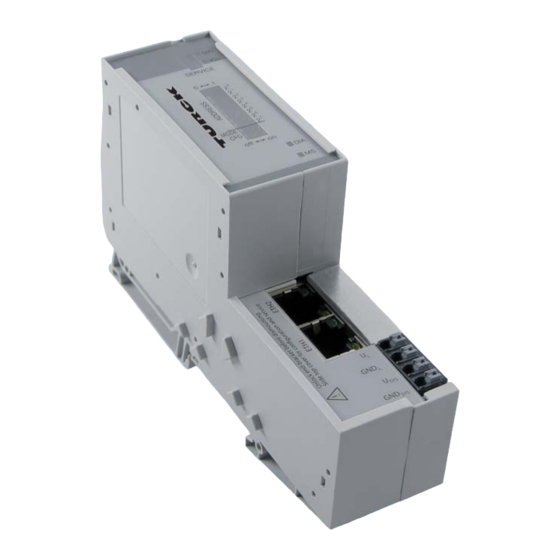
Page 38: Technical Data
DDIP-switch for operation mode EDIP-switch for configuration storage FLED for the MODE EtherNet connection GEtherNet-switch with EtherNet- LEDs Htension clamps for field supply Itension clamps for system supply GND L U SYS GND SYS D301174 1211 - BL20-ECO EtherNet/IP... -
Page 39: Block Diagram
Technical data 4.3.1 Block diagram The BL20 gateway has the following structure: Figure 4-2: Service Block diagram Module bus Switch 24 V Eth1 Eth2 Gateway 4.3.2 General technical data of a station Attention The auxiliary power supply must comply with the stipulations of SELV (Safety Extra Low Voltage) according to IEC 364-4-41. - Page 40 11 ms, in each case in ± direction per space coordinate Resistance to repetitive shock according to IEC 1 000 shocks, half-sinus 25 g peak value/6 ms, in 68-2-29 each case in ± direction per space coordinate D301174 1211 - BL20-ECO EtherNet/IP...
-
Page 41: Approvals And Tests
DIN IEC 68-2-30, temperature +55 °C / 131 °F, duration 2 cycles every 12 h; device in use Operational life MTBF 120 000 h Pollution severity according to IEC 664 (EN 61 131-2) Protection class according to IEC 529 IP20 D301174 1211 - BL20-ECO EtherNet/IP... -
Page 42: Technical Data For The Push-In Tension Clamp Terminals
This device can cause radio disturbances in residential areas and in small industrial areas (residential, business and trading). In this case, the operator can be required to take appropriate measures to suppress the disturbance at his own cost. D301174 1211 - BL20-ECO EtherNet/IP... -
Page 43: Connection Options At The Gateway
GND L U SYS GND SYS 4.4.1 Voltage supply The BL20-E-GW-EN provides an integrated power supply unit an push-in tension clamps for: field supply (U , GND system supply (U , GND 4.4.2 Field bus connection via Ethernet-switch The BL20-ECO-gateways for Ethernet provide an integrated RJ45-Ethernet-switch. - Page 44 In order to connect the gateway’s service-interface to the PC, a commercial cable with mini USB connector (e.g. commonly used for digital cameras) is necessary. Figure 4-5: Mini-USB- female connec- tor at the gate- SERVICE MODE 4-10 D301174 1211 - BL20-ECO EtherNet/IP...
-
Page 45: Address Setting
Function of the DIP-switches The DIP-switches for address setting, operation mode setting and for the storage of the station configuration are located under the gateway’s upper label. Figure 4-6: DIP-switches at the gateway SERVICE MODE 4-11 D301174 1211 - BL20-ECO EtherNet/IP... -
Page 46: Manual Address Allocation Via Dip-Switches 2
. The addresses 0 and 255 are used for Broadcast-messages in the subnet. The switch MODE has to be set to "OFF" Note All other network settings are stored in the module’s non-volatile EEPROM and can not be changed. 4-12 D301174 1211 - BL20-ECO EtherNet/IP... - Page 47 The gateway’s field bus address results from the addition of the valences (2 to 2 ) of the active DIP- switches (position = 1). Note Pull the label upwards out of the housing in order to reach the DIP-switches. 4-13 D301174 1211 - BL20-ECO EtherNet/IP...
-
Page 48: Led-Behavior
After changing the position of the DIP-switches, a voltage reset must be carried out to store the new address. LED-behavior During the module’s start-up, the "MS" LED shortly becomes constant red. After the successful start-up, the LED becomes solid green and the station is then ready for communication. 4-14 D301174 1211 - BL20-ECO EtherNet/IP... -
Page 49: Address Setting Via Dhcp-Mode
In "manual allocation", a client's IP address is assigned by the network administrator, and DHCP is used simply to convey the assigned address to the client. 4-15 D301174 1211 - BL20-ECO EtherNet/IP... -
Page 50: Address Setting Via Bootp-Mode
During it’s start-up, the module waits for the address setting via the BootP-server. This is indicated by the red flashing "MS" LED. The LED begins to flash green, as soon as the address setting via the server is completed. The station is ready for communication. 4-16 D301174 1211 - BL20-ECO EtherNet/IP... -
Page 51: Address Setting Via Pgm-Mode
During it’s start-up, the module waits for the address setting via the BootP-server. This is indicated by the red flashing "MS" LED. The LED begins to flash green, as soon as the address setting via the server is completed. The station is ready for communication. 4-17 D301174 1211 - BL20-ECO EtherNet/IP... -
Page 52: Address Setting Via Pgm-Dhcp-Mode
During it’s start-up, the module waits for the address setting via the BootP-server. This is indicated by the red flashing "MS" LED. The LED begins to flash green, as soon as the address setting via the server is completed. The station is ready for communication. 4-18 D301174 1211 - BL20-ECO EtherNet/IP... -
Page 53: Address-Setting Via I/O-Assistant 3 (Fdt/Dtm)
Naturally, the access to the single station via the service interface at the gateway is possible as well. The IP address, as well as the subnet mask of the TURCK Ethernet modules, can be changed according to the application by using the Busaddress Management function of the BL Service Ethernet interface in the I/O-ASSISTANT. - Page 54 Technical features Figure 4-13: Busaddress management Figure 4-14: Search for Network- nodes ASearch function in the busaddress management 4-20 D301174 1211 - BL20-ECO EtherNet/IP...
- Page 55 Address setting The IP address as well as the subnet mask of the TURCK Ethernet gateways can be changed according to the application by using the integrated Busaddress Management function in the IO-ASSISTANT 3 (FDT/DTM). Note The access of the IO-ASSISTANT to the gateway is only possible if the gateway is operated in...
-
Page 56: Storing The Station Configuration
Technical features Storing the station configuration 4.6.1 DIP-switch CFG The DIP-switch "CFG" at the gateway serves to take-over the Current Configuration of the BL20-station as Required Configuration to the gateway’s non-volatile memory. Figure 4-16: DIP-switch for storing the current station... -
Page 57: Status Indicators/Diagnostic Messages Gateway
Via the respective configuration software (IO-ASSISTANT) or Modbus-Client 4.7.1 Diagnostic messages via LEDs Every BL20 gateway displays the following statuses via LEDs: 2 LEDs for module bus communication (module bus LEDs): GW and IOs 2 LEDs for the Ethernet communication (fieldbus-LEDs): LINK/ACT and MS. - Page 58 – Replace the gateway. the gateway – short circuit in connected module – hardware error in gateway Non-adaptable modification of the – Compare the planned BL20 station flashing, physically connected station. with the physical station. 1 Hz – Check the physical station for defective or incorrectly fitted electronics modules.
- Page 59 Status indicators/diagnostic messages gateway Table 4-6: Status Meaning Remedy LED-displays Green Displays an active CIP Class 1 I/O connection Green, Gateway is ready for operation flashing Gateway indicates error Red, DHCP/BootP search of settings flashing 4-25 D301174 1211 - BL20-ECO EtherNet/IP...
-
Page 60: Diagnostic Messages Via The Process Data
4.7.2 Diagnostic Messages via the Process Data Besides the evaluation of diagnostic data via Explicit Messages, BL20 for EtherNet/IP offers the possibility of mapping diagnostic data into the gateways’ process data. 2 different forms of diagnostic data handling are provided:... -
Page 61: Status And Control Word Of The Gateway
Status register 2 (page 5-28). 4.8.2 Control word The control word is mapped into the station‘s process data. At present, it is not used but reserved for further use (see also Mapping of process data (page 5-15). 4-27 D301174 1211 - BL20-ECO EtherNet/IP... -
Page 62: Module Specific Diagnostic Messages
Module specific diagnostic messages Detailed module specific diagnostic messages can be read out from Gateway Class VSC 100, Object Instance 2, Gateway Instance, attribute 116 (0×74) "MODULE DIAG SUMMARY" (for detailed information, see also page 5-28). 4-28 D301174 1211 - BL20-ECO EtherNet/IP... -
Page 63: Implementation Of Ethernet/Ip
The EtherNet/IP communications profile..................3 5.1.1 I/O Messages......................................3 5.1.2 Explicit Messages....................................3 5.1.3 Communications profile of the BL20 EtherNet/IP gateway....................3 – Point to point.....................................3 – Multicast ......................................3 – COS I/O Connection ..................................3 – Cyclic I/O Connection ..................................4 – UCMM........................................4 – Connected Explicit messaging..............................4 Classes and instances of the EtherNet/IP-gateway ................ - Page 64 Digital versatile module class (VSC117).............................84 – Object instance....................................84 5.3.18 Analog versatile module class (VSC118) ...........................88 – Object instance....................................88 5.3.19 SWIRE module class (VSC121) ...............................91 – Object instance....................................91 5.3.20 RFID-S module class (VSC124)...............................96 – Object Instance .....................................96 D301174 1211 - BL20-ECO EtherNet/IP...
-
Page 65: The Ethernet/Ip Communications Profile
A reserved byte follows the service code, which is followed by the General Status code. 5.1.3 Communications profile of the BL20 EtherNet/IP gateway The EtherNet/IP gateway behaves as an EtherNet/IP Server in the network; the scanner of the higher- level controller operates as a EtherNet/IP Client. -
Page 66: Cyclic I/O Connection
The Connection ID is a number that is associated with a communication relationship. Receiving nodes decode this key to know whether they must accept the data or not. D301174 1211 - BL20-ECO EtherNet/IP... -
Page 67: Classes And Instances Of The Ethernet/Ip-Gateway
Classes and instances of the EtherNet/IP-gateway Classes and instances of the EtherNet/IP-gateway 5.2.1 EtherNet/IP standard classes The BL20 gateway supports the following EtherNet/IP Standard Classes in accordance with the CIP specification. Table 5-1: Class Object-name Description EtherNet/IP code standard classes 01 (0×01) -
Page 68: Identity Object (0×01)
Implementation of EtherNet/IP 5.2.2 Identity Object (0×01) The following description of the Identity Object is taken from the CIP specification, Vol. 1, Rev. 2.1, by ODVA & ControlNet International Ltd. and adapted to BL20. Class attributes Table 5-2: Attr. Attribute name... - Page 69 Returns a predefined listing of this objects attributes. 05 (0x05) Reset Starts the Reset service for the device. 14 (0x0E) Get_Attribute_Single Returns the contents of a specified attribute. 16 (0x10) Set_Attribute_Single Modifies a single attribute. D301174 1211 - BL20-ECO EtherNet/IP...
-
Page 70: Message Router Object (0×02)
The following description of the Message Router Object is taken from the CIP specification, Vol. 1, Rev. 2.1 by ODVA & ControlNet International Ltd. and adapted to BL20. Class attributes Table 5-6: Attr. -
Page 71: Message Router Request/Response Formats
The path is referencing an object class, instance or structure unknown element that is not known or is not contained in the processing node. Path processing shall stop when a path destination unknown error is encountered. D301174 1211 - BL20-ECO EtherNet/IP... - Page 72 The attribute data of this object was not saved prior to the data requested service. Store operation The attribute data of this object was not saved due to a failure failure during the attempt. 5-10 D301174 1211 - BL20-ECO EtherNet/IP...
- Page 73 Invalid Member ID The Member ID specified in the request does not exist in the specified Class/Instance/Attribute Member not settable A request to modify a non-modifiable member was received 5-11 D301174 1211 - BL20-ECO EtherNet/IP...
- Page 74 This range of error codes is to be used to indicate Object Class Class and service specific errors. Use of this range should only be performed when errors none of the Error Codes presented in this table accurately reflect the error that was encountered. 5-12 D301174 1211 - BL20-ECO EtherNet/IP...
-
Page 75: Assembly Object (0×04)
Assembly Objects bind attributes of multiple objects to allow data to or from each object to be sent or received over a single connection. The following description of the Assembly Object is taken from the CIP specification, Vol. 1, Rev. 2.1 by ODVA & ControlNet International Ltd. and adapted to BL20. Class attributes Table 5-12: Attr. -
Page 76: Instance 101
103 output assembly instance: 104 The size of each assembly instance can be retrieved through the assembly object, instance 0x67, attribute: 0x04 and can vary between 2 and 496 bytes. 5-14 D301174 1211 - BL20-ECO EtherNet/IP... -
Page 77: Mapping Of Process Data
Mapping of process data The process image of the BL20 gateway is depicted in WORD format (16 bit). The process data of successive modules of the same type, with process data of less than 1 word, are grouped together until 16 bits of process data is reached. -
Page 78: Connection Manager Object (0×06)
This object is used for connection and connectionless communications, including establishing connections across multiple subnets. The following description of the Connection Manager Object is taken from the CIP specification, Vol. 1, Rev. 2.1 by ODVA & ControlNet International Ltd. and adapted to BL20. Common services Table 5-16:... - Page 79 2 (0×02) ATTRIBUTE PORT UINT NUMBER 3 (0×03) ATTRIBUTE PORT UINT OBJECT EPATH 0x12, 0x02 Logical 0x00, 0x00 path Common services Table 5-19: Service code Class Instance Service name Common 01 (0x01) Get_Attribute_All services 14 (0x0E) Get_Attribute_Single 5-17 D301174 1211 - BL20-ECO EtherNet/IP...
-
Page 80: Tcp/Ip Interface Object (0×F5)
Implementation of EtherNet/IP 5.2.7 TCP/IP Interface Object (0×F5) The following description of the TCP/IP Interface Object is taken from the CIP specification, Vol. 2, Rev. 1.1 and adapted to BL20. Class attributes Table 5-20: Attr. Attribute name Get/ Type Value Class attributes 1 (0×01) - Page 81 Classes and instances of the EtherNet/IP-gateway Common services Table 5-22: Service code Class Instance Service name Common 01 (0x01) Get_Attribute_All services 02 (0x02) Set_Attribute_All 14 (0x0E) Get_Attribute_Single 16 (0×10) Set_Attribute_Single 5-19 D301174 1211 - BL20-ECO EtherNet/IP...
- Page 82 0 = The device shall use the interface configuration values previously stored (for example, in non-volatile memory or via hardware switches, etc). 1 to 3 = reserved DNS Enable Always 0. 5-31 Reserved Set to 0. 5-20 D301174 1211 - BL20-ECO EtherNet/IP...
- Page 83 FQDN option in the DHCP request. If the Host Name attribute has not been configured, then the device shall not include the FQDN option in the DHCP request. 5-21 D301174 1211 - BL20-ECO EtherNet/IP...
- Page 84 DHCP enabled valid stored config. valid Waiting configuration Set_Attributes BOOTP/DHCP request received response received Applying Status = configuration 0×00000000 Configuration applied TCP/IP network Change interface interface configured configuration Status = 0×00000001 5-22 D301174 1211 - BL20-ECO EtherNet/IP...
-
Page 85: Ethernet Link Object (0×F6)
Classes and instances of the EtherNet/IP-gateway 5.2.8 Ethernet Link Object (0×F6) The following description of the Ethernet Link Object is taken from the CIP specification, Vol. 2, Rev. 1.1 by ODVA & ControlNet International Ltd. and adapted to BL20. Class attributes Table 5-26: Attr. - Page 86 0 = interface detects no local hardware fault 1 = a local hardware fault is detected Common services Table 5-29: Service Class Instance Service name Common code services 01 (0x01) Get_Attribute_All 14 (0x0E) Get_Attribute_Single 76 (0×4C) Enetlink_Get_and_Clear 5-24 D301174 1211 - BL20-ECO EtherNet/IP...
-
Page 87: Vsc-Vendor Specific Classes
VSC-Vendor Specific Classes VSC-Vendor Specific Classes In addition to supporting the above named CIP Standard Classes, the BL20 gateway for EtherNet/IP supports the below vendor specific classes. The VSC describing the possible DeviceNet™-master function (VSC 122 and VSC 123) of an EtherNet/IP gateway can be found in a separate manual (D301118). -
Page 88: Class Instance Of The Vsc
Description VSC-Vendor Code Specific Classes dec. (hex.) RS485/422 module class (VSC115) (page Describes the modules of the type BL20- 5-69) 1RS485/422 SSI module class (VSC116) (page 5-76) Describes the modules of the type BL20- 1SSI Digital versatile module class (VSC117) -
Page 89: Gateway Class (Vsc 100)
VSC-Vendor Specific Classes 5.3.1 Gateway Class (VSC 100) The Gateway Class contains all the parameters that concern the BL20 system and the gateway. Note Please refer to paragraph "Class instance of the VSC", page 9-6, for the description of the class instance for the VSC. - Page 90 Offers slot-related information. Bit 7 = 1 module missing Bit 6 = 1 wrong module plugged DWORD Diag: Contains the module diagnostic information. Module diagnostic bits that are not used are indicated by a "0". 5-28 D301174 1211 - BL20-ECO EtherNet/IP...
-
Page 91: Object Instance 2
Allows to enable/disable the GW status register (0×8A) Register which is part of the input data. GW Control Get/ UINT Allows to enable/disable the GW control register (0×8B) Register which is part of the output data. 5-29 D301174 1211 - BL20-ECO EtherNet/IP... -
Page 92: Terminal Slot Class (Vsc 101)
It is not responding to data transmitted or received via I/O Connection Messages. PROCESSING (1): A BL20 module, recognized by the fieldbus is occupying a slot. Data transfer is taking place with the other fieldbus devices via I/O Connection Messages. - Page 93 (71h) BYTE module. Referenced USINT The VSC that represents this BL20 module. If this (72h) module is contained in the internal gateway library, then it is listed in a specific VSC that describes the typical attributes of the module. Referenced VSC...
-
Page 94: Process Data Class (Vsc102)
(65h) USINT Instance. Standard packed ARRAY OF Output process data, 16-bit aligned, compressed. (66h) process output WORD data Process data byte USINT The number of bytes that are exchanged with this (67h) count Instance. 5-32 D301174 1211 - BL20-ECO EtherNet/IP... -
Page 95: Object Instance 3, Diagnostic Instance
Changes become valid after a start-up! Object instance 4, COS/CYCLIC instance Table 5-38: Attr. Attribute name Get/ Type Description Object instance 4, COS/CYCLIC dec. instance (hex.) COS data ENUM Currently not supported (68h) mapping USINT 5-33 D301174 1211 - BL20-ECO EtherNet/IP... -
Page 96: Power Supply Module Class (Vsc103)
– 0x1F: analog volt./curr. mod. – 0x22: counter/incr. encoder 32bit – 0x28: SSI interface – 0x31: starter, mechanical – 0x32: starter, electronical – 0x41: RS232 mod. – 0x42: RS485/RS422 mod. – 0x51: CVI mod. – etc. 5-34 D301174 1211 - BL20-ECO EtherNet/IP... - Page 97 Attr. Attribute name Get/ Type Description Object instance dec. (hex.) Module command ARRAY The control interface of the BL20 module. (6Ch) interface ARRAY OF: BYTE: Control byte sequence Module response ARRAY Response interface of the BL20 module. (6Dh interface ARRAY OF:...
-
Page 98: Digital Input Module Class (Vsc104)
Describes the module type: (6Bh) USINT see attribute 107 (6Bh) on page 5-34 Module command ARRAY The control interface of the BL20 module. (6Ch) interface ARRAY OF: BYTE: Control byte sequence Module response ARRAY Response interface of the BL20 module. - Page 99 Params DWORD Contains the parameters of the module. (73h) DWORD: Bit for bit assignment according to module specification. Module registered ENUM Contains the index numbers specified in all the (74h) index USINT module lists. 5-37 D301174 1211 - BL20-ECO EtherNet/IP...
-
Page 100: Digital Output Module Class (Vsc105)
Describes the module type: see attribute 107 (6Bh) USINT (6Bh) on page 5-34 Module command ARRAY The control interface of the BL20 module. (6Ch) interface ARRAY OF: BYTE: Control byte sequence Module response ARRAY Response interface of the BL20 module. - Page 101 Params DWORD Contains the parameters of the module. (73h) DWORD: Bit for bit assignment according to module specification. Module registered ENUM Contains the index numbers specified in all the (74h) index USINT module lists. 5-39 D301174 1211 - BL20-ECO EtherNet/IP...
-
Page 102: Analog Input Voltage Module Class (Vsc106)
Describes the module type: see attribute 107 (6Bh) USINT (6Bh) on page 5-34 Module command ARRAY The control interface of the BL20 module. (6Ch) interface ARRAY OF: BYTE: Control byte sequence Module response ARRAY Response interface of the BL20 module. - Page 103 BYTE mode: Bit0: Voltage mode: 0 =0..10V 1 =-10V..+10V Bit 1: Value representation 0 =Integer (15Bit + sign) 1 =12Bit (left-justified) Bit 2: Diagnostic: 0 = enable 1 = disable Bit 3 to 7: reserved 5-41 D301174 1211 - BL20-ECO EtherNet/IP...
-
Page 104: Analog Output Voltage Module Class (Vsc107)
Describes the module type: see attribute 107 (6Bh) USINT (6Bh) on page 5-34 Module command ARRAY The control interface of the BL20 module. (6Ch) interface ARRAY OF: BYTE: Control byte sequence Module response ARRAY Response interface of the BL20 module. - Page 105 1 to 8 of the analog output modules. (88h - Only those channels are supported that are 8Fh) defined in attribute 111, "Number of supported channels". Attribute 136 contains the data for channel 1, attribute 143 for channel 8. 5-43 D301174 1211 - BL20-ECO EtherNet/IP...
-
Page 106: Analog Input Current Module Class (Vsc108)
127 for channel 8. BYTE diag: Bit 0: 0 = ok 1 = measurement value range error Bit 1: 0 = ok 1 = open circuit (only measurement range to 20 mA) Bit 2 to 7: reserved 5-44 D301174 1211 - BL20-ECO EtherNet/IP... - Page 107 1 = 4 to 20 mA Bit 1: Value representation: 0 = Integer (15 Bit + sign) 1 = 12 Bit (left-justified) Bit 2: Diagnostic: 0 = enable 1 = disable Bit 3 to 7: reserved 5-45 D301174 1211 - BL20-ECO EtherNet/IP...
-
Page 108: Analog Output Current Module Class (Vsc109)
Bit 0: Current mode: 0 = 0 to 20 mA 1 = 4 to 20 mA Bit 1: Value representation: 0 = Integer (15 Bit + sign) 1 = 12 Bit (left-justified) Bit 2 to 7: reserved 5-46 D301174 1211 - BL20-ECO EtherNet/IP... - Page 109 1 to 8 of the analog output modules. (88h - Only those channels are supported that are 8Fh) defined in attribute 111, "Number of supported channels". Attribute 136 contains the data for channel 1, attribute 143 for channel 8. 5-47 D301174 1211 - BL20-ECO EtherNet/IP...
-
Page 110: Analog Input Pt100/Ni Module Class (Vsc110)
Describes the module type: see attribute 107 (6Bh) USINT (6Bh) on page 5-34 Module command ARRAY The control interface of the BL20 module. (6Ch) interface ARRAY OF: BYTE: Control byte sequence Module response ARRAY Response interface of the BL20 module. - Page 111 127 for channel 8. BYTE diag: Bit 0: 0 = ok 1 = measurement value range error Bit 1: 0 = ok 1 = open circuit Bit 2: 0 = ok 1 = short-circuit 5-49 D301174 1211 - BL20-ECO EtherNet/IP...
- Page 112 Bit 2: Diagnose: 0 = release 1 = block Bit 3:Channel: 0 = activate channel 1 = deactivate channel Bit 4: Measurement mode: 0 = 2-wire 1 = 3-wire Bit 5 to 7: reserved 5-50 D301174 1211 - BL20-ECO EtherNet/IP...
- Page 113 8: Pt1000, -200...850 °C 9: Pt1000, -200...150 °C 10: Ni1000, -60...250 °C 11: Ni1000, -60...150 °C 12: resistance: 0...100 Ω 13: resistance: 0...200 Ω 14: resistance: 0...400 Ω 15: resistance: 0...1000 Ω 16 to 255: reserved 5-51 D301174 1211 - BL20-ECO EtherNet/IP...
-
Page 114: Analog Input Thermo Module Class (Vsc111)
Describes the module type: see attribute 107 (6Bh) USINT (6Bh) on page 5-34 Module command ARRAY The control interface of the BL20 module. (6Ch) interface ARRAY OF: BYTE: Control byte sequence Module response ARRAY Response interface of the BL20 module. - Page 115 0 = Integer (15 Bit + sign) 1 = 12 Bit (left-justified) Bit 2: Diagnose: 0 = release 1 = block Bit 3: Channel: 0 = activate channel 1 = deactivate channel Bit 4 to 7: reserved 5-53 D301174 1211 - BL20-ECO EtherNet/IP...
- Page 116 5: Type R -50..1760 °C 6: Type S -50..1540 °C 7: Type T -270..400 °C 8: ± 50 mV 9: ± 100 mV 10: ± 500 mV 11: ± 1000 mV 12 to 255: reserved 5-54 D301174 1211 - BL20-ECO EtherNet/IP...
-
Page 117: Counter Module Class (Vsc112)
Describes the module type: see attribute 107 (6Bh) USINT (6Bh) on page 5-34 Module command ARRAY The control interface of the BL20 module. (6Ch) interface ARRAY OF: BYTE: Control byte sequence Module response ARRAY Response interface of the BL20 module. - Page 118 Bit 3: 0 = ok 1 = lower limit wrong Bit 4: 0 = ok 1 = it is not permitted to invert the level of the digital input when using the latch retrigger function 5-56 D301174 1211 - BL20-ECO EtherNet/IP...
- Page 119 Bit 13: 0 = ok 1 = power limit wrong Bit 14: 0 = ok 1 = measurement operating mode wrong Bit 15: 0 = measurement Mode NOT active 1 = measurement Mode active 5-57 D301174 1211 - BL20-ECO EtherNet/IP...
- Page 120 – 0: CNT: single-action mode (CNT/ – 1: CNT: periodical MSRM) and are – 2 to 255: reserved not supported in the other operating mode. Please refer to Attribute No. 113 BASIC MODE. 5-58 D301174 1211 - BL20-ECO EtherNet/IP...
- Page 121 Defines if the diagnostic data of the DO1 are (7Eh) transmitted to the gateway. Diagnostic DO1: – FALSE: on Diagnostic data of the DO1 are being transmitted – TRUE: off Diagnostic data of the DO1 are not being transmitted 5-59 D301174 1211 - BL20-ECO EtherNet/IP...
- Page 122 – 2 to 255: reserved Sensor/input filter ENUM Defines the value of the input filter DI. (84h) (DI) USINT Sensor/input filter (DI): 0: 2.5 μs / 200 kHz 1: 25 μs / 20 kHz 2 to 255: reserved 5-60 D301174 1211 - BL20-ECO EtherNet/IP...
- Page 123 CPU/master STOP): – 0: turn off DO1 – 1: proceed with operating mode – 2: DO1 switch to Fault Value – 3: DO1 hold last value – 4 to 255:reserved 5-61 D301174 1211 - BL20-ECO EtherNet/IP...
-
Page 124: Rs232 Module Class (Vsc114)
Describes the module type: see attribute 107 (6Bh) USINT (6Bh) on page 5-34 Module command ARRAY The control interface of the BL20 module. (6Ch) interface ARRAY OF: BYTE: Control byte sequence Module response ARRAY Response interface of the BL20 module. - Page 125 1 = "parameter error": The set parameter values are not supported. – Bit 4: 0 = ok 1 = "hardware failure": The module has to be replaced, e.g. EEPROM or UART may be defect. 5-63 D301174 1211 - BL20-ECO EtherNet/IP...
- Page 126 RX count has been transmitted together with the last data segment of the process input data. RX count acknowledge is an acknowledge for the successful transmission of the data segment with RX count. 5-64 D301174 1211 - BL20-ECO EtherNet/IP...
- Page 127 TX data ARRAY OF Defines the transmit-data (0...7) (7Ch) BYTE TX data and ARRAY OF Defines the data to be transmitted via RS232 (7Dh) release BYTE (0...7) + transmission is released/ charged immediately reserved (7Eh) 5-65 D301174 1211 - BL20-ECO EtherNet/IP...
- Page 128 7 bytes of user data are available. 1 = "2byte ctrl/status header": The diagnostic data are part of the process input data, 6 bytes of user data are available. 5-66 D301174 1211 - BL20-ECO EtherNet/IP...
- Page 129 2 = "even" The number of the bits set to 1 is even (incl. data and parity bit). Stop ENUM Number of the stop bits. (86h) USINT 0 = "1 bit" 1 = "2 bits" 5-67 D301174 1211 - BL20-ECO EtherNet/IP...
- Page 130 XOFF USINT XOFF character (88h) character This sign is used to stop the data transfer to the data terminal equipment (DTE) with the activation of the software handshake. (0 - 255) default: 19/ 13h 5-68 D301174 1211 - BL20-ECO EtherNet/IP...
-
Page 131: Rs485/422 Module Class (Vsc115)
Describes the module type: see attribute 107 (6Bh) USINT (6Bh) on page 5-34 Module command ARRAY The control interface of the BL20 module. (6Ch) interface ARRAY OF: BYTE: Control byte sequence Module response ARRAY Response interface of the BL20 module. - Page 132 1 = "parameter error": The set parameter values are not supported. – Bit 4: 0 = ok 1 = "hardware failure": The module has to be replaced, e.g. EEPROM or UART may be defect. 5-70 D301174 1211 - BL20-ECO EtherNet/IP...
- Page 133 RX count has been transmitted together with the last data segment of the process input data. RX count acknowledge is an acknowledge for the successful transmission of the data segment with RX count. 5-71 D301174 1211 - BL20-ECO EtherNet/IP...
- Page 134 TX data ARRAY OF Defines the transmit-data (0...7) (7Ch) BYTE TX data and ARRAY OF Defines the data to be transmitted via RS485/422 (7Dh) release BYTE (0...7) + transmission is released/ charged immediately reserved (7Eh) 5-72 D301174 1211 - BL20-ECO EtherNet/IP...
- Page 135 7 bytes of user data are available. 1 = "2byte ctrl/status header": The diagnostic data are part of the process input data, 6 bytes of user data are available. 5-73 D301174 1211 - BL20-ECO EtherNet/IP...
- Page 136 2 = "even" The number of the bits set to 1 is even (incl. data and parity bit). Stop ENUM Number of the stop bits. (86h) USINT 0 = "1 bit" 1 = "2 bits" 5-74 D301174 1211 - BL20-ECO EtherNet/IP...
- Page 137 (DTE) with the activation of the software handshake. (0 - 255) default: 19/ 13h RS××× ENUM 0 = "RS422": (89h) mode USINT Parameterization as 422 1 = "RS485": Parameterization as 485 5-75 D301174 1211 - BL20-ECO EtherNet/IP...
-
Page 138: Ssi Module Class (Vsc116)
Describes the module type: see attribute 107 (6Bh) USINT (6Bh) on page 5-34 Module command ARRAY The control interface of the BL20 module. (6Ch) interface ARRAY OF: BYTE: Control byte sequence Module response ARRAY Response interface of the BL20 module. - Page 139 Bit 7: – 0 = The SSI encoder is read cyclically. – 1 = "SSI communication suspended" Communication with the SSI encoder is stopped as STOP = 1 (process output) or ERR_PARA = 1. 5-77 D301174 1211 - BL20-ECO EtherNet/IP...
- Page 140 – 0 = A comparison of the register contents has produced the following result: (REG_SSI_POS) ≠ (REG_CMP2) – 1 = "CMP2 register value matches POS" A comparison of the register contents has produced the following result: (REG_ SSI_POS) = (REG_CMP29 5-78 D301174 1211 - BL20-ECO EtherNet/IP...
- Page 141 – 1 = "control register write acknowledged" A modification of the register contents by a process output was initiated, i.e. WRITE OPERATION = 1. A write job would not be accepted with the next telegram of process output data. 5-79 D301174 1211 - BL20-ECO EtherNet/IP...
- Page 142 – 1 = "compare/flag CMP1 active" Comparison active, i.e. the data bits 8 to 10 of the "Diagnostics and status" attribute always have a value based on the result of the comparison with the actual SSI encoder value. 5-80 D301174 1211 - BL20-ECO EtherNet/IP...
- Page 143 The structure contains both parts: (7Ah) execute UINT – Address of the register to be written. DWORD – Value to be written. The write operation is executed without checking whether a write job is already present. 5-81 D301174 1211 - BL20-ECO EtherNet/IP...
- Page 144 0 = ZERO test of data cable. 1 = "disable SSI error detection" After the last valid bit, a ZERO test of the data cable is not carried out. Bit 6 to 15: reserved 5-82 D301174 1211 - BL20-ECO EtherNet/IP...
- Page 145 INVALID BITS LSB. The invalid bits on the MSB side are zeroed by masking the position value. I NVALID BITS MSB + INVALID BITS LSB must always be less than FRAME LENGTH. Default: 0 = 0hex 5-83 D301174 1211 - BL20-ECO EtherNet/IP...
-
Page 146: Digital Versatile Module Class (Vsc117)
Describes the module type: see attribute 107 (6Bh) USINT (6Bh) on page 5-34 Module command ARRAY The control interface of the BL20 module. (6Ch) interface ARRAY OF: BYTE: Control byte sequence Module response ARRAY Response interface of the BL20 module. - Page 147 Cable error_1 DWORD This attribute contains diagnosis information (7Bh) about a wire break (channel 1 to 32). Cable error_2 DWORD This attribute contains diagnosis information (7Ch) about a wire break (channel 33 to 64). 5-85 D301174 1211 - BL20-ECO EtherNet/IP...
- Page 148 Enables the high side output driver of channels (8Ah) output driver_1 (channel 1 to 32). Enable high side DWORD Enables the high side output driver of channels (8Bh) output driver_2 (channel 33 to 64). 5-86 D301174 1211 - BL20-ECO EtherNet/IP...
- Page 149 Activates the fault value for the channel (channel (91h) 33 to 64). Block Diagnostics DWORD Channel specific diagnostic information is (92h) blocked (channel 1 to 32). Block DWORD Channel specific diagnostic information is (93h) Diagnostics blocked (channel 33 to 64). 5-87 D301174 1211 - BL20-ECO EtherNet/IP...
-
Page 150: Analog Versatile Module Class (Vsc118)
Describes the module type: see attribute 107 (6Bh) USINT (6Bh) on page 5-34 Module command ARRAY The control interface of the BL20 module. (6Ch) interface ARRAY OF: BYTE: Control byte sequence Module response ARRAY Response interface of the BL20 module. - Page 151 4 to 20 Open circuit error WORD Indicates an open circuit in the signal line for the (91h) operating mode Short circuit error WORD (92h) reserved (93h) 5-89 D301174 1211 - BL20-ECO EtherNet/IP...
- Page 152 Value ENUM Sets the value representation for the channels: (B5h) representation 0 = default channel 1 1 = 16 bit integer 2 = 12 bit left justified + diagnostics. (C4h) Value representation channel 16 5-90 D301174 1211 - BL20-ECO EtherNet/IP...
-
Page 153: Swire Module Class (Vsc121)
VSC-Vendor Specific Classes 5.3.19 SWIRE module class (VSC121) This class contains all the parameters and information for the BL20-E-SWIRE module. Note The SWIRE module class (VSC121) is only implemented in gateways with Maj. Rev. ≥ 1.6.0. Attention In this class, chosen parameter options can only be deactivated by activating another option of this parameter. - Page 154 Slave 1 belongs to bit 0, slave 2 to bit 1 etc. 0: The bus is in data exchange mode 1: The configuration was not accepted, the bus does not switch to data exchange mode. (LED SW flashing) 5-92 D301174 1211 - BL20-ECO EtherNet/IP...
- Page 155 0: Configuration check based on device ID. Only SWIRE slaves with a device ID completely matching the set configuration are accepted on the bus 1: All slaves are mapped in 4Bit INPUT / 4Bit OUTPUT without checking the device ID. 5-93 D301174 1211 - BL20-ECO EtherNet/IP...
- Page 156 Bit 7: reserved Lifeguarding time USINT (7Ch) Default: 64 Disconnect: FF Setting of lifeguarding time, timeout time up to automatic reset of the slaves in the event of communication failure. (n × 10ms) (Default 1s) 5-94 D301174 1211 - BL20-ECO EtherNet/IP...
- Page 157 Bit4 reserved (7Eh), (7Fh) Param. SWIRE BYTE Bit 0 to bit 3 = type ident slave 1 Variant ID (7Eh) - = No slave Param. SWIRE = SWIRE-DIL-MTD (8Fh) type ident slave 16 5-95 D301174 1211 - BL20-ECO EtherNet/IP...
-
Page 158: Rfid-S Module Class (Vsc124)
Implementation of EtherNet/IP 5.3.20 RFID-S module class (VSC124) This class contains all information and parameters for the modules BL20-2RFID-S. Attention In this class, chosen parameter options can only be deactivated by activating another option of this parameter. Note Please refer to paragraph section "Class instance of the... - Page 159 Bypass time in ms (73h) channel 1 Bypass time WORD Bypass time in ms (74h) channel 2 Note For further information concerning the RFID communication interfaces see the special RFID documentation which can be downloaded from www.turck.com. 5-97 D301174 1211 - BL20-ECO EtherNet/IP...
- Page 160 Implementation of EtherNet/IP 5-98 D301174 1211 - BL20-ECO EtherNet/IP...
-
Page 161: Application Example: Bl20 Gateway With An Allen Bradley Plc
Application example: BL20 gateway with an Allen Bradley PLC General.............................. 2 6.1.1 Prerequisites for this example .................................2 – Example station ....................................2 Network configuration ........................3 Changing the IP address of a PC/ network interface card ..............4 6.3.1 Changing the IP address in Windows 2000/ Windows XP ....................4 6.3.2... -
Page 162: General
EtherNet/IP to an Allen Bradley PLC. 6.1.1 Prerequisites for this example In order to configure BL20 devices and to build up communications with the Allen Bradley ControlLogix PLC over EtherNet/IP, the following software tools and hardware devices are necessary. Software:... -
Page 163: Network Configuration
The BL20 gateways are delivered with the IP address 192.168.1.1. Note In order to build up the communication between the BL20 gateway and a PLC/ PC or a network interface card, both devices have to be hosts in the same network. -
Page 164: Changing The Ip Address Of A Pc/ Network Interface Card
Application example: BL20 gateway with an Allen Bradley PLC Changing the IP address of a PC/ network interface card 6.3.1 Changing the IP address in Windows 2000/ Windows XP The IP address is changed in the "Control Panel" in "Network and Dial-up Connections": 1 Open the folder "Local Area Connection"... -
Page 165: Changing The Ip Address In Windows Nt
2 Activate TCP/IP connection in the tab "Protocols" and click the "Properties" button. Figure 6-3: Network config- uration WIN NT 3 Activate "Specify IP address " and set the address as follows. Figure 6-4: Specify IP address D301174 1211 - BL20-ECO EtherNet/IP... -
Page 166: Changing The Ip Address Via Pactware™ (I/O-Assistant V3)
By means of the DTMs "Busaddress-Management" in the software I/O-ASSISTANT V3 (access via: "Additonal functions → Busaddress-Management") the entire Ethernet-network can be searched for TURCK-Ethernet-nodes. Their IP-address as well as their subnet -mask can be adapted according to the application (see also „Address-setting via I/O-ASSISTANT 3 (FDT/DTM)“, page 4-19). - Page 167 Windows fire- wall In the "Exceptions"-tab, add the the software PACTware™ to "Programs and Services". Pressing the button "Add Program..." opens the dialog "Add a Program". Select the PACTware™ from the list of installed programs. D301174 1211 - BL20-ECO EtherNet/IP...
-
Page 168: Address Setting Via Dhcp-Mode
Application example: BL20 gateway with an Allen Bradley PLC If necessary, use the button "Browse..." to choose the file "PACTware.exe" from the installation directory of the software. Figure 6-8: "Exceptions"- Despite an active firewall, the software PACTware™ is now able to browse the network for hosts and the address changing via the software is possible for the connected nodes. - Page 169 Note The DIP-switches on the gateway must be set to "400" in order to enable the DHCP-Mode. After having been connected to the network, the BL20 sends DHCP requests to the server using its MAC-ID. Figure 6-10:...
- Page 170 Application example: BL20 gateway with an Allen Bradley PLC The BootP/DHCP-Server sends the IP Address via BootP/DHCP to the BL20 gateway and, after a few seconds, the gateway answers with its new IP address when having stored it. Figure 6-12:...
-
Page 171: Setting-Up Communications With The Software Tool "Rslinx
In RSLinx, the "Autobrowse" function can be used to scan the network. All hosts in the network, which is defined by the settings of your network card, will be found. Figure 6-14: Scanning the EtherNet/IP network via RSWho 6-11 D301174 1211 - BL20-ECO EtherNet/IP... -
Page 172: Configuration Of The Network In "Rslogix 5000
Application example: BL20 gateway with an Allen Bradley PLC Configuration of the network in "RSLogiX 5000" The EtherNet/IP hosts (PLC, EtherNet/IP interface, I/O modules) have to be configured using the software "RSLogix 5000" (in this example version 15) from Rockwell Automation. -
Page 173: Configuration Of A Bl20 Station
If "Next" is selected, the "Module Properties" window displays information that will be available when the module is online. The configuration of the interface is completed. Press "Finish" to close the dialog box. 6.5.2 Configuration of a BL20 station 6-13 D301174 1211 - BL20-ECO EtherNet/IP... - Page 174 Application example: BL20 gateway with an Allen Bradley PLC Add the BL20 to the I/O configuration by using a right-click on the EtherNet/IP bridge module 1756- ENBT/A and select "New Module". Figure 6-20: Adding the BL20 station to the I/ O configuration Open "Communications"...
- Page 175 Instance 0×67, Attr. 0×04 and Assembly Class (0×04), Instance 0×68, Attr. 0×04. In the "Connection" tab set the "Requested Packet Interval" (RPI) to 10 ms, which normally should be the default setting. For BL20, the successfully tested RPI range is 5 and higher. Figure 6-23:...
-
Page 176: Downloading The I/O Configuration
Application example: BL20 gateway with an Allen Bradley PLC 6.5.3 Downloading the I/O configuration If the configuration of the network is completed, it can be downloaded to the controller by using for example the "Communication → Download" command. Figure 6-24:... - Page 177 If the correct communication path is set, it is possible to download the configuration. Once the I/O configuration is downloaded and the controller is in "Run" or "Remote Run" mode, the I/ O-data mapping of the BL20 station is shown in the "Controller Tags": Figure 6-29:...
-
Page 178: Examples For I/O Data Mapping
Application example: BL20 gateway with an Allen Bradley PLC Examples for I/O data mapping Each module is now accessible via the controller tags for viewing input data and/or forcing outputs. The data mapping depends on the data width of each module connected to the gateway. - Page 179 BL20:O.Data [3]; ch. 1 BL20-4DI-24VDC-P – Input data BL20:I.Data [8]; Bits 0 to 3 for ch. 0 to 3. BL20-1SSI – Input data BL20:I.Data [9 - 12] – Output data BL20:O.Data [4 - 7] 6-19 D301174 1211 - BL20-ECO EtherNet/IP...
-
Page 180: Mapping Report Via I/O-Assistant
Application example: BL20 gateway with an Allen Bradley PLC 6.6.1 Mapping report via I/O-ASSISTANT An EtherNet/IP I/O mapping report can be generated for each individual station by means of the software tool I/O-ASSISTANT. Figure 6-30: I/O mapping report in soft-... -
Page 181: Example For Process Data Access
Setting outputs at BL20-2DO-0.5A-P Example: To set the outputs "0" and "1" at module no. 2 in the example station (BL20-2DO-24VDC-0.5A-P), bit 0 bit 1 in output data word 1 (BL20:O.Data [1]) have to be set (see above Table 6-3: Data mapping for the example station). - Page 182 Application example: BL20 gateway with an Allen Bradley PLC 6-22 D301174 1211 - BL20-ECO EtherNet/IP...
-
Page 183: Guidelines For Station Planning
Extending an existing station ......................10 Firmware download ........................11 7.7.1 Firmware download: gateways with firmware version < V 1.2.0.4.................. 11 – DIP-switch position ..................................11 Firmware download: gateways with firmware version ≥ V 1.2.0.4.................. 12 7.7.2 D301174 1211 - BL20-ECO EtherNet/IP... -
Page 184: Module Arrangement
Module arrangement 7.1.1 Random module arrangement The arrangement of the I/O modules within a BL20 station can basically be chosen at will. Nevertheless, it can be useful with some applications to group certain modules together. Note A mixed usage of gateways of the BL20 ECO and the BL20 standard product line and I/O modules of both product lines (base modules with tension clamp terminals) is possible without any problems. -
Page 185: Maximum System Extension
Maximum system extension Maximum system extension The maximum number of modules within BL20 station with the gateway BL20-E-GW-EN-IP depends on the following factors: The station extension may not exceed the maximum number of 32 modules. The maximum permissible number of 192 communication bytes which are transmitted via the... - Page 186 25 mA BL20-16DO-24VDC-0.5A-P 120 mA BL20-32DO-24VDC-0.5A-P 30 mA BL20-1AO-I(0/4...20MA) 39 mA BL20-2AO-I(0/4...20MA) 40 mA BL20-2AO-U(-10/0...+10VDC) 43 mA BL20-E-4AO-U/I 50 mA BL20-2DO-R-NC 28 mA BL20-2DO-R-NO 28 mA BL20-2DO-R-CO 28 mA BL20-1CNT-24VDC 40 mA BL20-1RS232 140 mA D301174 1211 - BL20-ECO EtherNet/IP...
- Page 187 Module Number of Nominal current Communicatio communication bytes consumption at the n bytes and module bus nominal current consumptions of the BL20 modules BL20-1RS485/422 60 mA BL20-1SSI 50 mA BL20-E-1SWIRE 60 mA BL20-E-2RFID-S 30 mA D301174 1211 - BL20-ECO EtherNet/IP...
-
Page 188: Power Supply
4-9) 7.3.2 Module bus refreshing The number of BL20 modules, which can be supplied via the internal module bus by the gateway or a Bus Refreshing module depends on the modules’ nominal current consumptions at the module bus (see Table 7-1: Communication bytes and nominal current consumptions of the BL20... -
Page 189: C-Rail (Cross Connection)
PE connection of each power distribution module must be connected to the mounting rail via an additional PE terminal, which is available as an accessory. The C-rail is not interrupted by the modules of the BL20-ECO-products. It is connected through the modules’ connection level. But, an access to the C-rail is not possible. - Page 190 C-rails can be used for a common voltage supply when relay modules are planned. To accomplish this, the load voltage is connected to a Power Feeding module with the BL20-P4x-SBBC base module with tension clamp or screw connection. All the following relay modules are then supplied with power via the C-rail.
-
Page 191: Direct Wiring Of Relay Modules
Power supply Cross-connecting relay module roots is achieved by the use of jumpers. The corresponding wiring diagram including the jumpers can be found the manuals for BL20 I/O modules (German D300716, English D300717). 7.3.5 Direct wiring of relay modules As well as the options mentioned above, relay modules can be wired directly. In this case, base modules without C-rail connections should be chosen to guarantee the potential isolation to the adjoining modules. -
Page 192: Protecting The Service Interface On The Gateway
BL20 enables the pulling and plugging of electronics modules without having to disconnect the field wiring. The BL20 station remains in operation if an electronics module is pulled. The voltage and current supplies as well as the protective earth connections are not interrupted. -
Page 193: Firmware Download
Firmware can only be downloaded via the service interface on the gateway using the software tool I/O-ASSISTANT 3 (FDT/DTM). It can not be downloaded via Ethernet. DIP-switch position Firmware download to the BL20-E-GW-EN-IP via serviceinterface, requires a special DIP-switch position: Table 7-2: Address... - Page 194 Firmware download: gateways with firmware version V 1.2.0.4 Actual gateways with a firmware version ≥ V 1.2.0.4 allow a firmware download by means of the software I/O-ASSISTANT 3 (FDT/DTM) also via the EtherNet-interface on the gateway. 7-12 D301174 1211 - BL20-ECO EtherNet/IP...
- Page 195 8.3.2 Grounding of inactive metal components..........................5 8.3.3 PE connection......................................5 8.3.4 Earth-free operation....................................5 8.3.5 Mounting rails .......................................6 Shielding of cables ..........................7 Potential compensation........................8 8.5.1 Switching inductive loads.................................8 8.5.2 Protection against Electrostatic Discharge (ESD) ........................8 D301174 1211 - BL20-ECO EtherNet/IP...
-
Page 196: General Notes
The cable duct joints must be electrically connected and the cable ducts must be earthed. Danger Observe all valid guidelines concerning internal and external lightning protection and grounding specifications when routing cables outside of buildings. D301174 1211 - BL20-ECO EtherNet/IP... -
Page 197: Lightning Protection
(10BaseT) with shielding (STP) or without shielding (UTP). Note TURCK offers a variety of cable types for fieldbus lines as premoulded or bulk cables with different connectors. The ordering information for the available cable types can be found in the BL20 catalog. -
Page 198: Potential Relationships
Potential relationships 8.2.1 General The potential relationship of a Ethernet system realized with BL20 modules is characterized by the following: The system supply of gateway and I/O-modules as well as the field supply are realized via one power feed at the gateway. -
Page 199: Electromagnetic Compatibility (Emc)
8.3.1 Ensuring Electromagnetic Compatibility The EMC of BL20 modules is guaranteed when the following basic rules are adhered to: Correct and large surface grounding of inactive metal components. Correct shielding of cables and devices. Proper cable routing – correct wiring. -
Page 200: Mounting Rails
Remove the isolating layer from all painted, anodized or isolated metal components at the connection point. Protect the connection point against corrosion (for example with grease; caution: use only suitable grease). D301174 1211 - BL20-ECO EtherNet/IP... -
Page 201: Shielding Of Cables
Note A further possibility is a double-shielded cable (galvanically separated), whereby the innermost shield is connected on one side and the outermost shield is connected on both sides. D301174 1211 - BL20-ECO EtherNet/IP... -
Page 202: Potential Compensation
8.5.2 Protection against Electrostatic Discharge (ESD) Attention Electronic modules and base modules are at risk from electrostatic discharge when disassembled. Avoid touching the bus connections with bare fingers as this can lead to ESD damage. D301174 1211 - BL20-ECO EtherNet/IP... -
Page 203: Bl20-Approvals For Zone 2/ Division
BL20-Approvals for Zone 2/ Division 2 Note The Zone 2 - approval certificates for BL20 can be found in a separate manual for approvals D301255 on www.turck.de. D301174 1211 - BL20-ECO EtherNet/IP... - Page 204 BL20-Approvals for Zone 2/ Division 2 D301174 1211 - BL20-ECO EtherNet/IP...
-
Page 205: 10 Appendix
– Process output data ..................................17 10.1.3 SSI-Modul ......................................19 – Process input data ..................................19 – Process output data (PDout)..............................22 10.2 Nominal current consumption and power loss ................24 10.3 Power loss of the modules ......................28 10-1 D301174 1211 - BL20-ECO EtherNet/IP... -
Page 206: Data Image Of The Technology Modules
10.1.1 Counter module Process input data - counter mode Process input data is data from the connected field device that is transmitted via the BL20-1CNT-24VDC module to the PLC. This is transferred in an 8-byte format as follows: 4 bytes are used to represent the counter value. - Page 207 This bit must be reset by the RES_STS control bit. STS_OFLW Status upper count limit Set if the counter goes above the upper count limit. This bit must be reset by the RES_STS control bit. 10-3 D301174 1211 - BL20-ECO EtherNet/IP...
- Page 208 This bit must be reset by the RES_STS control bit. STS_SYN Status synchronization After synchronization is successfully completed the STS_SYN status bit is set. This bit must be reset by the RES_STS control bit. 10-4 D301174 1211 - BL20-ECO EtherNet/IP...
-
Page 209: Process Input Data - Measurement Mode
Data image of the technology modules Process input data - measurement mode 4 bytes contain the measurement value 1 byte contains diagnosis information 2 bytes contain status messages Figure 10-2: PZDE counter, measurement mode 10-5 D301174 1211 - BL20-ECO EtherNet/IP... - Page 210 1: The lower measuring limit was undershot. The bit must be reset with RES_STS: 0 → 1. STS_OFLW 1: The upper measuring limit was exceeded. The bit must be reset with RES_STS: 0 → 1. 10-6 D301174 1211 - BL20-ECO EtherNet/IP...
-
Page 211: Process Output Data - Counter Mode
0 → 1. Process output data - counter mode The process output data is the data that is output from the PLC via the gateway to the BL20-1CNT- 24VDC module. The BL20 module allows some parameters to be modified during operation. - Page 212 "Reference value 1" or "Refer- ence value 2" Structure of the data bytes with “Function and behavior of DO1/DO2 Figure 10-4: Structure of the data bytes with “Function and behavior of DO1/ 10-8 D301174 1211 - BL20-ECO EtherNet/IP...
- Page 213 This control bit must then be reset again. Any new error messages are not set while the EXTF_ACK control bit is set! CTRL_ DO2 0: The virtual output DO2 is blocked. 1: The virtual output DO2 is released. 10-9 D301174 1211 - BL20-ECO EtherNet/IP...
- Page 214 “0“ → “1“: The value in bytes 0 to 3 is accepted as the new load value. PREPARE LOAD_VAL Parameter definition of Load counter direct “0“ → “1“: The value in bytes 0 to 3 is accepted directly as the new count value. 10-10 D301174 1211 - BL20-ECO EtherNet/IP...
-
Page 215: Process Output Data - Measurement Mode
Four bytes represent the parameter values for Lower limit or Upper limit, Function of DO1 or Integration time. Structure of the data bytes with „Function of DO1“ set Figure 10-5: Structure of the data bytes with „Function of DO1“ 10-11 D301174 1211 - BL20-ECO EtherNet/IP... - Page 216 Figure 10-6: Structure of the data bytes with „Lower limit“ or „Upper limit“ set Structure of the data bytes with „Integration time set“ Figure 10-7: Structure of the data bytes with „Integration time set“ 10-12 D301174 1211 - BL20-ECO EtherNet/IP...
- Page 217 0 A 1: The value in bytes 0 to 3 is accepted directly as the new lower measuring limit. LOAD_LOLIMIT: 0 to 199 999 999 x10 0 to 24 999 999 x 10 0 to 99 999 999 ms 10-13 D301174 1211 - BL20-ECO EtherNet/IP...
- Page 218 STS_UFLW = 1 (process input). – 10: Output DO1 indicates a value below the lower measuring limit. STS_UFLW = 1 (process input) – 11:Output DO1 indicates a value above the upper measuring limit. STS_OFLW = 1 (process input) 10-14 D301174 1211 - BL20-ECO EtherNet/IP...
-
Page 219: 10.1.2 Rs×××-Module
10.1.2 RS×××-module Process input data The incoming data are stored in the receive-buffer of the BL20-1RS××× module, segmented and transferred to the PLC via the module bus and the gateway. The transmission is realized in a 8-byte format, structured as follows: 1 status byte, used to guarantee error free data-transmission. - Page 220 This value is transferred together with every data segment. The RX_CNT values are sequential: 00->01->10->11->00... (decimal: 0->1->2->3->0...) Errors in this sequence show the loss of data segments. RX_BYTE_CNT Number of the valid bytes in this data segment. 10-16 D301174 1211 - BL20-ECO EtherNet/IP...
-
Page 221: Process Output Data
Data image of the technology modules Process output data Process output data are data which are sent from the PLC via the gateway and the BL20-1RS××× module to a connected field device. The data received from the PLC are loaded into the transmit- buffer in the BL20-1RS××× module. - Page 222 Errors in this sequence show the loss of data segments. TX_BYTE_CNT 0 - 7 Number of the valid user data in this data segment. In PROFIBUS- DP, the data segments contain a maximum number of 6 bytes of user data. 10-18 D301174 1211 - BL20-ECO EtherNet/IP...
-
Page 223: 10.1.3 Ssi-Modul
The field input data is transferred from the connected field device to the BL20-1SSI module. The process input data is the data that is transferred to the PLC from the BL20-1SSI via a gateway. This is transferred in an 8 byte format as follows: 4 bytes are used for representing the data that was read from the register with the address stated at REG_RD_ADR. - Page 224 The SSI encoder values are decremented or the values are constant. The SSI encoder values are incremented. STS_DN (LED DN) The SSI encoder values are incremented or the values are constant. The SSI encoder values are decremented. 10-20 D301174 1211 - BL20-ECO EtherNet/IP...
- Page 225 Operation of the module is not possible with the present parameter set. STS_UFLW A comparison of the register contents has produced the following result: (REG_SSI_POS) ≥ (REG_LOWER_LIMIT) A comparison of the register contents has produced the following result: (REG_SSI_POS) < (REG_LOWER_LIMIT) 10-21 D301174 1211 - BL20-ECO EtherNet/IP...
- Page 226 The field output data is transferred from the BL20-1SSI module to the connected field device. The process output data is the data that is output from the PLC to the BL20-1SSI module via a gateway. This is transferred in an 8 byte format as follows: 4 bytes are used for representing the data that is to be written to the register with the address specified at REG_WR_DATA.
- Page 227 Comparison active, i.e. the data bits REL_CMP1, STS_CMP1 and FLAG_CMP1 have a value based on the result of the comparison with the SSI encoder value. STOP Request to read the SSI encoder cyclically Request to interrupt communication with the encoder 10-23 D301174 1211 - BL20-ECO EtherNet/IP...
-
Page 228: Nominal Current Consumption And Power Loss
≤ 12mA BL20-2AI-I(0/4..20MA) ≤ 50 mA BL20-1AI-U(-10/0..+10VDC) ≤ 12 mA BL20-2AI-U(-10/0..+10VDC) BL20-2AI-PT/NI-2/3 < 30 mA BL20-2AI-THERMO-PI < 30 mA BL20-2DO-24VDC-0.5A-P 20 mA (when load current = 0) BL20-2DO-24VDC-0.5A-N 20 mA (when load current = 0) 10-24 D301174 1211 - BL20-ECO EtherNet/IP... - Page 229 ≤ 50 mA BL20-2AO-U(-10/0..+10VDC) BL20-2DO-R-NC < 20 mA BL20-2DO-R-NO < 20 mA BL20-2DO-R-CO < 20 mA BL20-1CNT-24VDC < 50 mA (when load current = 0) BL20-2RFID-A < 100 mA (when load current = 0) 10-25 D301174 1211 - BL20-ECO EtherNet/IP...
- Page 230 ≤ 41 mA BL20-1AI-U(-10/0...+10VDC) ≤ 35 mA BL20-2AI-U(-10/0...+10VDC) ≤ 45 mA BL20-2AI-PT/NI-2/3 ≤ 45 mA BL20-2AI-THERMO-PI ≤ 32 mA BL20-2DO-24VDC-0.5A-P ≤ 32 mA BL20-2DO-24VDC-0.5A-N ≤ 33 mA BL20-2DO-24VDC-2A-P ≤ 30 mA BL20-4DO-24VDC-0.5A-P ≤ 45 mA BL20-16DO-24VDC-0.5A-P 10-26 D301174 1211 - BL20-ECO EtherNet/IP...
- Page 231 ≤ 39 mA BL20-1AO-I(0/4...20MA) ≤ 40 mA BL20-2AO-I(0/4...20MA) ≤ 43 mA BL20-2AO-U(-10/0...+10VDC) ≤ 28 mA BL20-2DO-R-NC ≤ 28 mA BL20-2DO-R-NO ≤ 28 mA BL20-2DO-R-CO ≤ 40 mA BL20-1CNT-24VDC BL20-2RFID-A 30 mA BL20-E-1SWIRE 60 mA 10-27 D301174 1211 - BL20-ECO EtherNet/IP...
-
Page 232: Power Loss Of The Modules
BL20-2AI-THERMO-PI BL20-2DO-24VDC-0.5A-P BL20-2DO-24VDC-0.5A-N BL20-2DO-24VDC-2A-P BL20-4DO-24VDC-0.5A-P < 1 W BL20-16DO-24VDC-0.5A-P < 4 W BL20-2DO-120/230VAC-0.5A < 1 W BL20-1AO-I(0/4..20MA) < 1 W BL20-2AO-I(0/4..20MA) < 1 W BL20-2AO-U(-10/0..+10VDC) < 1 W BL20-2DO-R-NC BL20-2DO-R-NO BL20-2DO-R-CO BL20-1CNT-24VDC 1.3 W 10-28 D301174 1211 - BL20-ECO EtherNet/IP... -
Page 233: 11 Glossary
Time required for a master to serve all slaves or stations in a bus system, i. e. reading inputs and writing outputs. Bus line Smallest unit connected to a bus, consisting of a PLC, a coupling element for modules on the bus and a module. 11-1 D301174 1211 - BL20-ECO EtherNet/IP... - Page 234 All objects that produce, convert, transmit, distribute or utilize electrical power (e. g. conductors, cable, machines, control devices). Electromagnetic compatibility – the ability of an electrical part to operate in a specific environment without fault and without exerting a negative influence on its environment. 11-2 D301174 1211 - BL20-ECO EtherNet/IP...
- Page 235 Input/output. Impedance Total effective resistance that a component or circuit has for an alternating current at a specific frequency. 11-3 D301174 1211 - BL20-ECO EtherNet/IP...
- Page 236 Most Significant bit Ping Implementation of an echo-protocol, used for testing whether a particular host is operating properly and is reachable on the network from the testing host. 11-4 D301174 1211 - BL20-ECO EtherNet/IP...
- Page 237 Type of information transmission, by which data is transmitted bit by bit via a cable. Setting parameters Setting parameters of individual stations on the bus and their modules in the configuration software of the master. Shield Conductive screen of cables, enclosures and cabinets. 11-5 D301174 1211 - BL20-ECO EtherNet/IP...
- Page 238 Connection of a conductive component with the grounding connection via a grounding installation. Topology Geometrical structure of a network or the circuitry arrangement. Abbreviation for User Datagram Protocol. UDP is an transport protocol for the connectionless data between Ethernet hosts. Unidirectional Working in one direction. 11-6 D301174 1211 - BL20-ECO EtherNet/IP...
- Page 239 ................. 3-4 ........... 8-4 –manufacturer identifier potential-compensation cable ..........3-4 ........8-8 –netmask power distribution ................ 3-5 ............2-4 –network classes power loss ............3-5 ..............10-24 –subnet ID power supply ..............3-5 ............4-9 12-1 D301174 1211 - BL20-ECO EtherNet/IP...
- Page 240 ......3-3 TCP/IP host ..............3-5 Terminal slot class ............5-28 UCMM ................5-4 VSC-Vendor Specific Classes ........5-25 WIN 2000 ................ 6-4 WIN NT ................6-5 WIN XP ................6-4 Zone 2 ................9-1 12-2 D301174 1211 - BL20-ECO EtherNet/IP...
- Page 241 Hans Turck GmbH & Co. KG 45472 Mülheim an der Ruhr Germany Witzlebenstraße 7 Tel. +49 (0) 208 4952-0 Fax +49 (0) 208 4952-264 E-Mail more@turck.com Internet www.turck.com...
Need help?
Do you have a question about the BL20 and is the answer not in the manual?
Questions and answers