Advertisement
CellComRT Digital Cellular Communicator
Description
The CellComRT Digital Cellular Communicator provides a fully supervised alarm communication path over the GSM/
GPRS network. The CellComRT is installed remote from the panel enclosure in a supplied plastic housing and can be
powered directly from the XR100 or XR500 Series panel LX header or can be powered from an optional power supply.
What is Included
The CellComRT includes the following:
• One Remote Cellular Communicator
• One 380-400 SecureCom Wireless SIM Card
• Plastic Housing
• One 383 Rubber Duck Antenna
• One CELLCOMBAT Lithium Polymer Rechargeable Battery
Compatibility
The CellComRT is compatible with the XR100, XR100N, XR500,
XR500N and XR500E Command Processors using software Version
203 or higher. The CellComRT operates on the panel LX header
and can be used with an 1100 Series Wireless Receiver.
Installation Safety
Ground Yourself Before Handling the Panel! To discharge
static, touch any grounded metal, such as the enclosure,
before touching the panel.
Remove All Power From the Panel! Remove all AC and Battery power from the panel before installing or connecting
any modules, cards, or wires to the panel.
Bus Connection
The CellComRT interfaces with the XR100/XR500 Series using the panel's on-board LX-Bus header (J22). The
CellComRT can be mounted up to 100 feet from the panel enclosure using 22 AWG wire or 250 feet using 18 AWG
wire.
Harness Connection
Use the following steps to connect the CellComRT to the panel:
1. Install a jumper across the header pins next to the letter "X" on the XR100/XR500 panel's J23 header.
2. Connect the 4-wire harness from the J22 header on the CellComRT to the XR100/XR500 panel's LX-Bus header (J22).
3. After power-up of the CellComRT, briefly reset the XR100/XR500 panel using the J16 jumper to activate
operation.
Installing the CellComRT
Connecting Backup Rechargeable Battery
Observe polarity and connect the rechargeable battery lead connector to the 2-pin CellCom J4
battery header.
Tamper Switches
The CellComRT is equipped with two tamper switches. One is located inside the housing. The
second tamper is a wall tamper switch. Before mounting the CellComRT unit, follow these steps
to install the tamper springs:
1. Place the included tamper springs on the tamper switches. The long tamper spring installs
inside the housing and the short tamper spring installs in the opening in the back of the
CellComRT housing.
2. With spring in place, mount the CellComRT on a flat surface that engages the tamper
spring and closes the tamper. See Figure 1 for mounting hole locations.
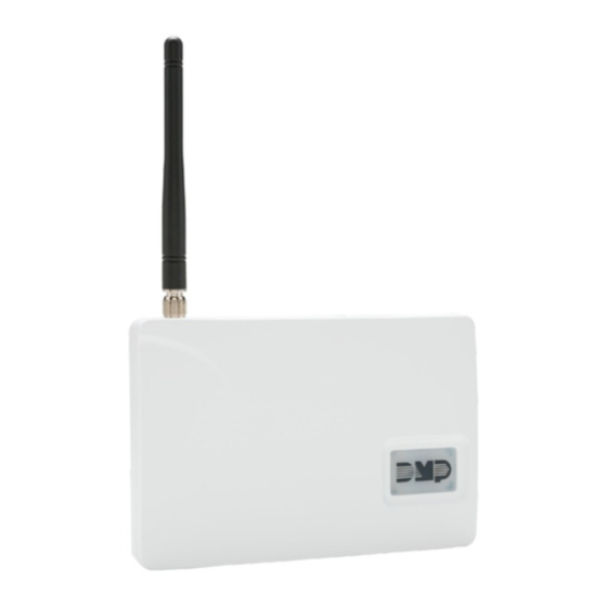
Connecting the Antenna to the CellComRT
Attach the Rubber Duck Antenna to the Antenna SMA Connector (J19) located on the top right
side of the CellComRT. See Figure 2.
Inst alla tIon GuIde
J22
Transmit LED
Battery
J4
CellComRT
Mounting Holes
Figure 1: CellComRT PCB
CellCom
Transmit LED
J22
J16 Reset
Battery
J4
Charge LED
SIM Card
Antenna
Holder
S2
Tamper
Switch
Shoulder Washer
Mounting Screw
Rubber Duck
Antenna
J19
Antenna
J5
Figure 2: CellComRT
SIM Card
S2
Antenna Installation
Holder
Tamper
Switch
J25
J19
Advertisement
Table of Contents

Subscribe to Our Youtube Channel
Related Manuals for DMP Electronics CellComRT


Summary of Contents for DMP Electronics CellComRT
- Page 1 The CellComRT Digital Cellular Communicator provides a fully supervised alarm communication path over the GSM/ GPRS network. The CellComRT is installed remote from the panel enclosure in a supplied plastic housing and can be powered directly from the XR100 or XR500 Series panel LX header or can be powered from an optional power supply.
-
Page 2: Led Indicator
To LX Header (J22) on Figure 4. XR100/XR500 panel 4. Plug the power supply into a 110 Volt AC outlet not controlled by a switch. Figure 4: Optional Plug-in Transformer Installation Programming/Activation Cellular Service is required before using the CellComRT for signal transmission. Using Remote Link panel communication programming, select CELL as one of the Communication paths. The CellComRT comes with a SIM card ready for activation with SecureCom Wireless, LLC. More information is available at www.securecomwireless. com or refer to the Remote Link Guide (LT-0565). Or, use a SIM card provided by the GPRS carrier of your choice. LED Indicator The CellCom Green Transmit LED light flashes when transmission is being made between the CellComRT and the panel. -
Page 3: Rechargeable Battery
2. Snap the battery assembly in place. 3. Observe polarity and connect the battery lead connector to the CellCom J4 battery header. Battery Assembly Standoff CellComRT Antenna Antenna SIM Card CellComRT Holder SIM Card Transmit LED Holder Transmit LED Tamper Tamper Switch Switch Battery Battery Figure 5: Battery Assembly Standoffs Figure 6: CellComRT Assembly Digital Monitoring Products CellCom Installation Guide... - Page 4 CellCom System Messages The following messages are communicated to the DMP SCS-1R receiver to indicate CellCom status: 130 WARNING: Cell Communicator Bus Failed COMMUNICATION SECURITY FEATURE The communication on the bus between the panel and the cellular communicator has failed while no areas of the system were armed. This message may originate from both the panel and the cellular communicator as both monitor the bus. The restoral message is S132.
-
Page 5: Fcc Information
- Reorient or relocate the receiving antenna. - Increase the separation between the equipment and receiver. - Connect the equipment into an outlet on a circuit different from that to which the receiver is connected. - Consult the dealer or an experienced radio/TV technician for help. Listed Compliance Specifications Commercial Burglary For listed installations, the CellComRT may be installed in the following configurations: • Installed and directly powered from the control panel. • Installed and powered from a UL 603 listed power supply. The additional on board standby Lithium-Ion battery, CELLCOMBAT, is considered auxiliary operation and has not been evaluated by UL. The optional Model 376 Plug-in DC Power Supply is considered auxiliary operation and has not been evaluated by UL. Digital Monitoring Products CellCom Installation Guide... -
Page 6: Specifications
ANSI/UL 1610 Central Station Burglar Alarm Units 383 Rubber Duck Antenna Export Control 386 Wall Mount Antenna Bracket The CellComRT uses AES encryption and any export beyond CELLCOMBAT Replacement Rechargeable the United States must be in accordance with Export Battery assembly Administration Regulations. 8 0 0 - 6 4 1 - 4 2 8 2 I n t r u s I o n • f I r e • A c c e s s • n e t w o r k s w w w .
Need help?
Do you have a question about the CellComRT and is the answer not in the manual?
Questions and answers