Advertisement
Quick Links
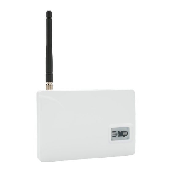
CellCom
TM
COMMUNICATOR
Compliance Listing Guide
BEFORE YOU BEGIN
This guide provides compliance information for the CellCom Series Universal Alarm Communicator. The CellCom‑LTE‑V
Series Universal Alarm Communicator provides a fully supervised alarm communication path for any burglary,
commercial fire, or residential fire control panel. DMP recommends that you read through the contents of this guide
before starting the installation process. It describes the functions along with available installation options. Information
contained in this guide allows you to learn the operation, functionality, and programming features of the communicator
to meet specific applications. This guide covers all the requirements for installing the CellComSLCF and CellComF‑LTE‑V
Universal Alarm Communicators for Commercial Fire installations. This document applies to the following models:
•
CellComSLC
•
CellComSLCZ
•
CellComSLCF
•
CellCom‑LTE‑V
•
CellComZ‑LTE‑V LTE Cellular Communicator with Z‑Wave
•
CellComF‑LTE‑V LTE Cellular Communicator for Commercial Fire
PROGRAMMING REQUIREMENTS
System Programming Option Requirements
Notice to users, installers, authorities that have jurisdiction, and other involved parties: This product incorporates
field‑programmable software. In order for the product to comply with the requirements of a certificated installation,
certain programming features or options must be limited to specific values or not used at all as indicated below.
PROGRAM FEATURE OR OPTION
System Reports, RESTORAL
Communication, CHECKIN MINUTES
Output Options, COMM FAIL OUT
APPLICATIONS
CID Dialer Connection
Directly connect the tip and ring from the control panel to the communicator. See Figure 1. This connection captures
Contact ID messages from any fire panel that are based on the SIA communication standard DC‑05‑1999.09‑DCS.
Messages are then formatted into a Serial 3 message and sent to a DMP Model SCS‑1R Receiver or SCS‑VR Receiver.
Note: CID Dialer Connection cannot be used when using Zone 4 Bell Connection. Do not connect telephone
company wires to the communicator. Remove any connected telephone company wires from the control panel.
Control Panel
The panel or separate power
supply must be 12 Volt Regulated
and Power Limited.
12VDC Aux. Output
Ground
Bell +
Bell -
Telephone
Jack
Connector
SERIES UNIVERSAL ALARM
CDMA Cellular Communicator
CDMA Cellular Communicator with Z‑Wave
CDMA Cellular Communicator for Commercial Fire
LTE Cellular Communicator
STANDARD
ANSI/UL 864
ANSI/UL 864
ANSI/UL 864
Use 18-22 AWG for
Power Supply connection
+
-
Figure 1: CellCom Series Wiring Diagram for Tip and Ring Connection
PERMITTED?
POSSIBLE SETTINGS
Y
NO, YES, DISARM
Y
3‑250
Y
0, 1, 2
MODEL
CellComSLC
J8
B
R
J9
S3
+12
G
SETTINGS PERMITTED
YES, DISARM
3‑58
1, 2
S1
S2
Z1
Z2
Z3
G
Z4+
Z4-
O1
O2
T
R
RESET
S1
LOAD
S2
Advertisement

Subscribe to Our Youtube Channel
Related Manuals for DMP Electronics CellCom series


Summary of Contents for DMP Electronics CellCom series
-
Page 1: Before You Begin
Compliance Listing Guide BEFORE YOU BEGIN This guide provides compliance information for the CellCom Series Universal Alarm Communicator. The CellCom‑LTE‑V Series Universal Alarm Communicator provides a fully supervised alarm communication path for any burglary, commercial fire, or residential fire control panel. DMP recommends that you read through the contents of this guide before starting the installation process. - Page 2 Control Panel (FACP) 12/24VDC Aux Output Ground Use EOL specified by FACP FACP Zone Input Connect to terminal with lowest voltage FACP Zone Input Figure 3: CellComSLCF and CellComF-LTE-V Wiring Diagram for FACP CellCom SERIES COMPLIANCE LISTING GUIDE DIGITAL MONITORING PRODUCTS...
- Page 3 Program and install the equipment to comply with NFPA basic fire requirements. Refer to the Universal Fire Alarm Specifications and ANSI/UL 864 Specifications in this document. Z-Wave Note: Z‑Wave functionality has not been evaluated by UL. DIGITAL MONITORING PRODUCTS | CellCom SERIES COMPLIANCE LISTING GUIDE...
-
Page 4: Fcc Notice
This booklet is available from the U.S. Government Printing Office, Washington D.C. 20402 Stock No. 004‑000‑00345‑4 Information furnished by DMP is believed to be accurate and reliable. This information is subject to change without notice. CellCom SERIES UNIVERSAL ALARM Certifications COMMUNICATOR Cellular •...
Need help?
Do you have a question about the CellCom series and is the answer not in the manual?
Questions and answers