Advertisement
Quick Links
265LTE-V CELLULAR
COMMUNICATOR
Installation Guide
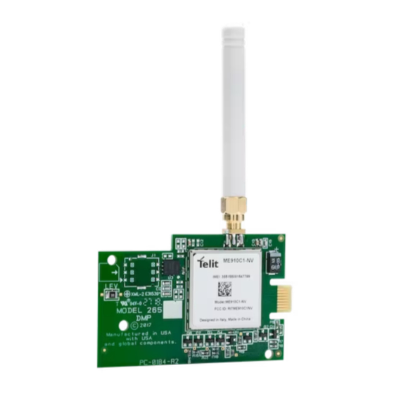
Figure 1: 265LTE-V PCB
DESCRIPTION
The 265LTE-V Cellular
Communicator provides
a fully-supervised alarm
communication path over the
LTE network.
The 265LTE-V is installed on
the XTLplus
and powered
TM
by the panel so no additional
enclosure, power supply, or
battery back-up is needed.
Compatibility
All DMP XTLplus Series
panels.
What is Included
•
265LTE-V Cellular
Communicator
•
External Antenna
1
INSTALL THE 265LTE-V
Caution: Touch grounded metal to discharge
static before handling the XTLplus.
1.
Place the antenna onto the 265LTE-V SMA
connector and then twist the antenna until it
is securely tightened.
2.
Slide the 265LTE-V into the XTLplus eight-
pin CELL MODULE connector, keeping the
265LTE-V parallel to the XTLplus.
3.
Align the standoff hole in the 265LTE-V with
the standoff on the XTLplus, and then snap it
into place. See Figure 2.
External
Antenna
SMA
Connector
Standoff
Hole
Figure 2: Installing the 265LTE-V
2
ACTIVATE THE 265LTE-V
Cellular service is required before using the
265LTE-V for signal transmission. The 265LTE-V
comes ready for activation with SecureCom
Wireless. Use Remote Link
site (dealeradmin.securecomwireless.com),
the Tech APP
(1-866-266-2826) to activate the 265LTE-V.
Remote Link Activation
1.
Navigate to Remote Link and select a panel.
2.
Select Program in the top menu and select
Communications from the drop-down
menu.
3.
Select Cellular Network as the
Communication Type and click Activate.
4.
Select SIM as the SIM Type.
5.
Enter the SIM number found on the
265LTE-V label and click Activate.
6.
Select a Rate Plan for the 265LTE-V and
click Activate.
Eight-Pin CELL MODULE
Connector
LOAD
RESET
PROG
+ DC -
R
B
on the XTLplus
, the Dealer Admin
TM
, or call DMP Customer Service
TM
TM
TM
Advertisement

Subscribe to Our Youtube Channel
Related Manuals for DMP Electronics 265LTE-V


Summary of Contents for DMP Electronics 265LTE-V
-
Page 1: Installation Guide
Slide the 265LTE-V into the XTLplus eight- pin CELL MODULE connector, keeping the 265LTE-V parallel to the XTLplus. Align the standoff hole in the 265LTE-V with the standoff on the XTLplus, and then snap it into place. See Figure 2. - Page 2 The panel provides a diagnostic function to test the communication integrity and cellular signal strength of the 265LTE-V to the nearest tower for the cellular carrier. To use the diagnostic function, reset the panel, enter 2313 (DIAG), and press CMD.
-
Page 3: Fcc Information
établies par le Code de sécurité 6 de Santé Canada. Le système doit être installé à une distance minimale de 7.87 pouces (20 cm) séparant l’antenne d’une personne présente en conformité avec les limites permises d’exposition du grand public. 265LTE-V Installation Guide Digital Monitoring Products, Inc. -
Page 4: Specifications
265LTE-V CELLULAR Compatibility COMMUNICATOR XTL+Z (Firmware Version 172 or higher) XTL+W (Firmware Version 172 or higher) XTL+WZ (Firmware Version 172 or higher) Specifications Certifications Primary Power 12VDC Cellular FCC Part 15: RI7CE910C1NV Current Draw Industry Canada: 5131A-ME910C1NV Intertek (ETL) Listed...
Need help?
Do you have a question about the 265LTE-V and is the answer not in the manual?
Questions and answers