Table of Contents
Advertisement
Available languages
Available languages
Quick Links
LOVATO ELECTRIC S.P.A.
24020 GORLE (BERGAMO) ITALIA
VIA DON E. MAZZA, 12
TEL. 035 4282111
FAX (Nazionale): 035 4282200
FAX (International): +39 035 4282400
L
E
E-mail info@
ovato
lectric.com
L
E
Web
www.
ovato
lectric.com
The complete operating manual is
downloadable from website
www.lovatoelectric.com
Il manuale operativo completo è
scaricabile dal sito www.lovatoelectric.com
GB
DMG200 - DMG210
D
Available in German at www.LovatoElectric.com/I269D.pdf
PL
Available in Polish at www.LovatoElectric.com/I269PL.pdf
WARNING!
– Carefully read the manual before the installation or use.
– This equipment is to be installed by qualified personnel, complying to current standards, to avoid damages or safety hazards.
– Before any maintenance operation on the device, remove all the voltages from measuring and supply inputs and short-circuit the CT input terminals.
– The manufacturer cannot be held responsible for electrical safety in case of improper use of the equipment.
– Products illustrated herein are subject to alteration and changes without prior notice. Technical data and descriptions in the documentation are accurate, to
the best of our knowledge, but no liabilities for errors, omissions or contingencies arising there from are accepted.
– A circuit breaker must be included in the electrical installation of the building. It must be installed close by the equipment and within easy reach of the operator.
It must be marked as the disconnecting device of the equipment: IEC /EN 61010-1 § 6.11.2.
– Fit the instrument in an enclosure or cabinet with minimum IP40 degree protection.
– Clean the device with a soft dry cloth; do not use abrasives products, liquid detergents or solvents.
INDEX
Introduction . . . . . . . . . . . . . . . . . . . . . . . . . . . . . . . . . . . . . . . . . . . . . . . . . . . . . . . . . . . . . . . . . . . . . . . . . . . . . . . . . . . . . . . . . . . . . . . . . . . . . . . . . . . . . . . . .
Description . . . . . . . . . . . . . . . . . . . . . . . . . . . . . . . . . . . . . . . . . . . . . . . . . . . . . . . . . . . . . . . . . . . . . . . . . . . . . . . . . . . . . . . . . . . . . . . . . . . . . . . . . . . . . . . . . .
Keyboard functions . . . . . . . . . . . . . . . . . . . . . . . . . . . . . . . . . . . . . . . . . . . . . . . . . . . . . . . . . . . . . . . . . . . . . . . . . . . . . . . . . . . . . . . . . . . . . . . . . . . . . . . . . . .
Display of readings . . . . . . . . . . . . . . . . . . . . . . . . . . . . . . . . . . . . . . . . . . . . . . . . . . . . . . . . . . . . . . . . . . . . . . . . . . . . . . . . . . . . . . . . . . . . . . . . . . . . . . . . . . .
Table of display pages . . . . . . . . . . . . . . . . . . . . . . . . . . . . . . . . . . . . . . . . . . . . . . . . . . . . . . . . . . . . . . . . . . . . . . . . . . . . . . . . . . . . . . . . . . . . . . . . . . . . . . . . .
Main menu . . . . . . . . . . . . . . . . . . . . . . . . . . . . . . . . . . . . . . . . . . . . . . . . . . . . . . . . . . . . . . . . . . . . . . . . . . . . . . . . . . . . . . . . . . . . . . . . . . . . . . . . . . . . . . . . . .
Password access . . . . . . . . . . . . . . . . . . . . . . . . . . . . . . . . . . . . . . . . . . . . . . . . . . . . . . . . . . . . . . . . . . . . . . . . . . . . . . . . . . . . . . . . . . . . . . . . . . . . . . . . . . . . .
Parameter setting (setup). . . . . . . . . . . . . . . . . . . . . . . . . . . . . . . . . . . . . . . . . . . . . . . . . . . . . . . . . . . . . . . . . . . . . . . . . . . . . . . . . . . . . . . . . . . . . . . . . . . . . . .
Parameter table . . . . . . . . . . . . . . . . . . . . . . . . . . . . . . . . . . . . . . . . . . . . . . . . . . . . . . . . . . . . . . . . . . . . . . . . . . . . . . . . . . . . . . . . . . . . . . . . . . . . . . . . . . . . . .
Energy meters page . . . . . . . . . . . . . . . . . . . . . . . . . . . . . . . . . . . . . . . . . . . . . . . . . . . . . . . . . . . . . . . . . . . . . . . . . . . . . . . . . . . . . . . . . . . . . . . . . . . . . . . . . . .
Hour counters page . . . . . . . . . . . . . . . . . . . . . . . . . . . . . . . . . . . . . . . . . . . . . . . . . . . . . . . . . . . . . . . . . . . . . . . . . . . . . . . . . . . . . . . . . . . . . . . . . . . . . . . . . . .
Trend graph page . . . . . . . . . . . . . . . . . . . . . . . . . . . . . . . . . . . . . . . . . . . . . . . . . . . . . . . . . . . . . . . . . . . . . . . . . . . . . . . . . . . . . . . . . . . . . . . . . . . . . . . . . . . . .
Commands menu . . . . . . . . . . . . . . . . . . . . . . . . . . . . . . . . . . . . . . . . . . . . . . . . . . . . . . . . . . . . . . . . . . . . . . . . . . . . . . . . . . . . . . . . . . . . . . . . . . . . . . . . . . . . .
Wiring test . . . . . . . . . . . . . . . . . . . . . . . . . . . . . . . . . . . . . . . . . . . . . . . . . . . . . . . . . . . . . . . . . . . . . . . . . . . . . . . . . . . . . . . . . . . . . . . . . . . . . . . . . . . . . . . . . .
Technical characteristics. . . . . . . . . . . . . . . . . . . . . . . . . . . . . . . . . . . . . . . . . . . . . . . . . . . . . . . . . . . . . . . . . . . . . . . . . . . . . . . . . . . . . . . . . . . . . . . . . . . . . . . .
Wiring diagrams. . . . . . . . . . . . . . . . . . . . . . . . . . . . . . . . . . . . . . . . . . . . . . . . . . . . . . . . . . . . . . . . . . . . . . . . . . . . . . . . . . . . . . . . . . . . . . . . . . . . . . . . . . . . . .
PC-DMG210 connection through RS485 interface . . . . . . . . . . . . . . . . . . . . . . . . . . . . . . . . . . . . . . . . . . . . . . . . . . . . . . . . . . . . . . . . . . . . . . . . . . . . . . . . . . .
Terminal arrangement. . . . . . . . . . . . . . . . . . . . . . . . . . . . . . . . . . . . . . . . . . . . . . . . . . . . . . . . . . . . . . . . . . . . . . . . . . . . . . . . . . . . . . . . . . . . . . . . . . . . . . . . . .
Mechanical dimensions . . . . . . . . . . . . . . . . . . . . . . . . . . . . . . . . . . . . . . . . . . . . . . . . . . . . . . . . . . . . . . . . . . . . . . . . . . . . . . . . . . . . . . . . . . . . . . . . . . . . . . . .
INTRODUCTION
The DMG200 and DMG210 multimeters have been designed to join the maximum possible ease of operation together with a wide choice of advanced functions.
Regardless of the compactness of the modular housing (only 4U), the multimeter performance is the same as high-end devices.
The graphic LCD offers user-friendly interface. The rich variety of functions makes the DMG series multimeters the ideal choice for a wide range of applications.
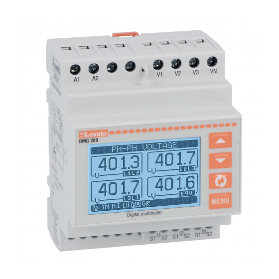
DESCRIPTION
– Modular DIN-rail housing, 4U (72mm wide)
– Graphic LCD display, 128x80 pixels, white backlighting, 4 grey levels
– Membrane keyboard with 4 keys for viewing and setting
– Easy and fast navigation
– Texts for measurements, setup and messages in 5 languages
– Reading of 160 electrical parameters
– DMG210 version with built-in RS485 interface
– True RMS measurements
– Continuous (gapless) sampling
– High accuracy.
KEYBOARD FUNCTIONS
L L and M keys - Used to scroll display pages, to select among possible choices, and to modify settings (increment-decrement).
key - Used to move through sub-pages, to confirm a choice, to switch between viewing modes.
MENU key - Used to enter or exit from viewing and setting menus.
DIGITAL MULTIMETER
Instructions manual
CZ
Available in Czech at www.LovatoElectric.com/I269CZ.pdf
RU
Available in Russian at www.LovatoElectric.com/I269RU.pdf
G
B
Page
1
1
1
2
2
3
3
3
4
5
6
6
6
6
7
8
9
9
9
1
Advertisement
Table of Contents

Related Manuals for LOVATO ELECTRIC DMG210L01


Summary of Contents for LOVATO ELECTRIC DMG210L01
- Page 1 DIGITAL MULTIMETER Instructions manual LOVATO ELECTRIC S.P.A. 24020 GORLE (BERGAMO) ITALIA VIA DON E. MAZZA, 12 TEL. 035 4282111 FAX (Nazionale): 035 4282200 FAX (International): +39 035 4282400 DMG200 - DMG210 E-mail info@ ovato lectric.com www. ovato lectric.com Available in German at www.LovatoElectric.com/I269D.pdf Available in Czech at www.LovatoElectric.com/I269CZ.pdf...
- Page 2 DISPLAY OF READINGS – The L and M keys allow to scroll the view pages of readings, one by one. The actual page being viewed is written in the title bar. – Some of the readings may not be shown, depending on the programming and the wiring of the device (for instance, if programmed-wired for a three-phase without neutral system, L-N voltage page is not shown).
-
Page 3: Password Access
MAIN MENU – The main menu is made up of a group of graphic icons (shortcuts) that allow rapid access to measurements and settings. – Starting from normal viewing press MENU key. The main menu screen is displayed. – Press L or M to select the required function. The selected icon is highlighted and the central part of the display shows the description of the function. –... -
Page 4: Parameter Table
– Select the sub-menu and press to show the parameters. – Each parameter is shown with code, description and programmed setting value. 1 - Parameter code 2 - Parameter description 3 - Present setting value 4 - Selected parameter – To modify the setting of one parameter, select it and then press –... - Page 5 M04 - INTEGRATION Default Range P04.01 Integration mode Shift Fixed / Shift P04.02 Power integration time 1-60 P04.03 Current integration time 1-60 P04.01 - Selection of average reading calculation method: Fixed = Readings are integrated for the set time. Every time the integration time elapses, the Average value is updated with the result of the last integration. Shift = The instantaneous values are integrated for a period f time equal to 1/15th of the set time.
-
Page 6: Commands Menu
HOUR COUNTERS PAGE – The Hour counters page shows the following meters simultaneously: • Total hour counter (counts the power-on time of the device) • Partial hour counter. – To clear counters it is necessary to access the commands menu. –... -
Page 7: Technical Characteristics
TECHNICAL CHARACTERISTICS Auxiliary supply Ambient conditions Nominal voltage Us 100-240V Operating temperature -20 to +60°C 110-250V Storage temperature -30 to +80°C Rated voltage range 85-264V Relative humidity <80% (IEC/EN 60068-2-78) 93.5-300V Maximum pollution degree Frequency 45-66Hz Measurement category Power consumption/dissipation DMG200: 3.5VA 1.2W Overvoltage category DMG210: 4.5VA 1.7W... -
Page 8: Wiring Diagrams
WIRING DIAGRAMS 3 phase connection with or without neutral 2 phase connection P01.07 = L1-L2-L3-N L1-L2-L3 P01.07 = L1-N-L2 100...240VAC 100...240VAC 110...250VDC 110...250VDC -- - V2 V3 S1 S2 S1 S2 S1 S2 AUX SUPPLY VOLTAGE CURRENT AUX SUPPLY VOLTAGE CURRENT Single phase connection Balanced 3 phase connection with or without neutral... - Page 9 PC-DMG210 CONNECTION THROUGH RS485 INTERFACE Max 1200m Cable 51C4 TR A RS485 Interface converter RS485 RS232/485 DMG210 n°31 DMG210 n°1 Max 1200m Max 1200m Cable 51C4 Repeat this wiring diagram up to 255 devices TR A TR A B SG TR A TR A RS485...
- Page 10 MULTIMETRO DIGITALE Manuale operativo LOVATO ELECTRIC S.P.A. 24020 GORLE (BERGAMO) ITALIA VIA DON E. MAZZA, 12 TEL. 035 4282111 FAX (Nazionale): 035 4282200 FAX (International): +39 035 4282400 DMG200 - DMG210 E-mail info@ ovato lectric.com www. ovato lectric.com Available in German at www.LovatoElectric.com/I269D.pdf Available in Czech at www.LovatoElectric.com/I269CZ.pdf...
-
Page 11: Visualizzazione Delle Misure
VISUALIZZAZIONE DELLE MISURE – I tasti L e M consentono di scorrere le pagine di visualizzazione misure una per volta. La pagina attuale è riconoscibile tramite la barra del titolo. – Alcune delle misure potrebbero non essere visualizzate in funzione della programmazione e del collegamento dell’apparecchio (ad esempio se programmato per un sistema senza neutro le misure riferite al neutro non vengono visualizzate). -
Page 12: Menu Principale
MENU PRINCIPALE – Il menu principale è costituito da un insieme di icone grafiche che permettono l’accesso rapido alle misure ed alle impostazioni. – Partendo dalla visualizzazione misure normale, premere il tasto MENU. Il display visualizza il menu rapido. – Premere L M per selezionare la funzione desiderata. L’icona selezionata viene evidenziata e la scritta nella parte centrale del display indica la descrizione della funzione. - Page 13 – Selezionare il sottomenu e premere il tasto per visualizzare i parametri. – Ciascun parametro è visualizzato con codice, descrizione e valore attuale. 1 - Codice parametro 2 - Descrizione parametro 3 - Valore attuale 4 - Parametro selezionato – Se si vuole modificare il valore di un parametro, dopo averlo selezionato premere –...
- Page 14 M04 - INTEGRAZIONE Default Range P04.01 Modo integrazione Scorr. Fisso / Scorrevole P04.02 Tempo integrazione potenze 1-60 P04.03 Tempo integrazione correnti 1-60 P04.01 - Selezione della modalità di calcolo delle misure integrate. Fisso = Le misure istantanee vengono integrate per il tempo impostato. Ad ogni scadenza del tempo, la misura integrata viene aggiornata con il risultato dell’ultima integrazione.
-
Page 15: Menu Comandi
PAGINA CONTAORE – Nella pagina contaore vengono visualizzati: • contatore totale (conta il tempo di alimentazione dell’apparecchio) • contaore parziale. – Per l’azzeramento dei contatori è necessario accedere al menu comandi. – La pagina contaore può essere disabilitata completamente se l’abilitazione generale contaore viene impostata su OFF (vedere menu Contaore). PAGINA GRAFICO TREND –... -
Page 16: Caratteristiche Tecniche
CARATTERISTICHE TECNICHE Alimentazione ausiliaria Condizioni ambientali Tensione nominale Us 100-240V Temperatura d’impiego -20 a +60°C 110-250V Temperatura di stoccaggio -30 a +80°C Limiti di funzionamento 85-264V Umidità relativa <80% (IEC/EN 60068-2-78) 93,5-300V Grado di inquinamento ambiente massimo Frequenza 45-66Hz Categoria di misura Potenza assorbita/dissipata DMG200: 3,5VA 1,2W Categoria dì... -
Page 17: Schemi Di Connessione
SCHEMI DI CONNESSIONE Connessione trifase con o senza neutro Connessione bifase P01.07 = L1-L2-L3-N L1-L2-L3 P01.07 = L1-N-L2 100...240VAC 100...240VAC 110...250VDC 110...250VDC -- - V2 V3 S1 S2 S1 S2 S1 S2 AUX SUPPLY VOLTAGE CURRENT AUX SUPPLY VOLTAGE CURRENT Connessione monofase Connessione trifase bilanciata con o senza neutro P01.07 = L1-N... - Page 18 CONNESSIONE PC-DMG210.. MEDIANTE INTERFACCIA RS485 Max 1200m Cable 51C4 TR A RS485 Interface converter RS485 RS232/485 DMG210 n°31 DMG210 n°1 Max 1200m Max 1200m Cable 51C4 Repeat this wiring diagram up to 255 devices TR A TR A B SG TR A TR A RS485...
- Page 19 MULTIMETRE NUMERIQUE Manuel d’application LOVATO ELECTRIC S.P.A. 24020 GORLE (BERGAMO) ITALIA VIA DON E. MAZZA, 12 TEL. 035 4282111 FAX (Nazionale): 035 4282200 FAX (International): +39 035 4282400 DMG200 - DMG210 E-mail info@ ovato lectric.com www. ovato lectric.com Available in German at www.LovatoElectric.com/I269D.pdf Available in Czech at www.LovatoElectric.com/I269CZ.pdf...
- Page 20 VISUALISATION DES MESURES – Les touches L et M permettent de défiler entre les pages de affichage mesures, une à une. La page visualisée est indiquée à la barre de titre. – Quelques mesures ne peuvent pas être visualisées en fonction de la programmation et de la connexion de l’appareil. Par exemple, si on programme un système sans le neutre, les mesures visées au neutre ne seront pas affichées.
-
Page 21: Réglage Des Paramètres (Setup)
MAIN MENU – The main menu is made up of a group of graphic icons (shortcuts) that allow rapid access to measurements and settings. – Starting from normal viewing press MENU key. The main menu screen is displayed. – Press L or M to select the required function. The selected icon is highlighted and the central part of the display shows the description of the function. –... - Page 22 – Sélectionnez le sous-menu et appuyez sur la touche pour afficher les paramètres. – Chaque paramètre est affiché avec le code, la description et la valeur actuelle. 1 - Code paramètre 2 - Description paramètre 3 - Valeur présente 4 - Paramètre chiosi –...
- Page 23 M04 - INTEGRATION Default Range P04.01 Mode d’intégration Défile Fixe / Défile P04.02 Temps intégration puissances 1-60 P04.03 Temps intégration courants 1-60 P04.01 - choix de la méthode de calcul en moyenne des mesures : Fixe = les mesures instantanées sont intégrées pour le temps programmé. Chaque fois que le temps d’intégration s’écoule, la valeur de mesure moyenne est mise à...
- Page 24 PAGE COMPTEURS HORAIRES – A la page compteurs horaires, les suivantes sont affichées: • Compteur total (comptage du temps quand l’appareil est sous tension) • Compteur partiel. – Il est nécessaire entrer au menu commandes pour l’opération de remise à zéro des compteurs. –...
-
Page 25: Caracteristiques Techniques
CARACTERISTIQUES TECHNIQUES Alimentation auxiliaire Environnement Tension assignée Us 100-240V Température d’emploi -20 à +60°C 110-250V Température de stockage -30 à +80°C Limites de fonctionnement 85-264V Humidité relative <80% (IEC/EN 60068-2-78) 93,5-300V Degré de pollution maxi Fréquence 45-66Hz Catégorie de mesure Consommation / dissipation puissance DMG200: 3,5VA / 1,2W Catégorie de surtension... - Page 26 SCHEMAS DE CONNEXION Connexion triphasée avec ou sans le neutre Connexion biphasée P01.07 = L1-L2-L3-N L1-L2-L3 P01.07 = L1-N-L2 100...240VAC 100...240VAC 110...250VDC 110...250VDC -- - V2 V3 S1 S2 S1 S2 S1 S2 AUX SUPPLY VOLTAGE CURRENT AUX SUPPLY VOLTAGE CURRENT Connnexion monophasée Connexion triphasée équilibrée avec ou sans le neutre...
- Page 27 CONNEXION PC-DMG210.. PAR INTERFACE RS485 Max 1200m Cable 51C4 TR A RS485 Interface converter RS485 RS232/485 DMG210 n°31 DMG210 n°1 Max 1200m Max 1200m Cable 51C4 Repeat this wiring diagram up to 255 devices TR A TR A B SG TR A TR A RS485...
- Page 28 MULTÍMETRO DIGITAL Manual de aplicación LOVATO ELECTRIC S.P.A. 24020 GORLE (BERGAMO) ITALIA VIA DON E. MAZZA, 12 TEL. 035 4282111 FAX (Nazionale): 035 4282200 FAX (International): +39 035 4282400 DMG200 - DMG210 E-mail info@ ovato lectric.com www. ovato lectric.com Available in German at www.LovatoElectric.com/I269D.pdf Available in Czech at www.LovatoElectric.com/I269CZ.pdf...
-
Page 29: Visualización De Las Medidas
VISUALIZACIÓN DE LAS MEDIDAS – Las teclas L y M permiten pasar las páginas de visualización una por una. La página actual se reconoce por la barra del título. – En base a la programación y conexión del aparato, es posible que algunos parámetros no se visualicen (por ejemplo si está programado para un sistema sin neutro, no se visualizarán los parámetros relacionados a este último). -
Page 30: Menú Principal
MENÚ PRINCIPAL – El menú principal consta de un conjunto de iconos gráficos que agilizan el acceso a las medidas y configuraciones. – Desde la visualización normal de los parámetros pulsar la tecla MENÚ. La pantalla visualiza el menú rápido. –... - Page 31 – Seleccionar el submenú y pulsar la tecla para visualizar los parámetros. – Cada parámetro se presenta con su código, descripción y valor actual. 1 - Código parámetro 2 - Descripción parámetro 3 - Valor actual 4 - Parámetro seleccionado –...
- Page 32 M04 - INTEGRACIÓN Default Range P04.01 Modo integración Var. Fijo / Variable P04.02 Tiempo integración potencias 1-60 P04.03 Tiempo integración corrientes 1-60 P04.01 - Selección del modo de cálculo de las medidas integradas. Fijo = Las mediciones instantáneas son integradas durante el tiempo programado. Cada vez que termina el tiempo, la medición integrada se actualiza con el resultado de la última integración.
-
Page 33: Página Cuentahoras
PÁGINA CUENTAHORAS – En la página cuentahoras se visualizan: • cuentahoras total (cuenta el tiempo de alimentación del aparato) • cuentahoras parcial . – Para poner a cero los contadores es necesario acceder al menú de mandos. – La página cuentahoras puede inhabilitarse por completo si la habilitación general cuentahoras está configurada en OFF (véase menú Cuentahoras). PÁGINA GRÁFICO TREND –... -
Page 34: Características Técnicas
CARACTERÍSTICAS TÉCNICAS Alimentación auxiliar Condiciones ambientales Tensión nominal Us 100-240V Temperatura de funcionamiento -20 a +60°C 110-250V Temperatura de almacenamiento -30 a +80°C Límites de funcionamiento 85-264V Humedad relativa <80% (IEC/EN 60068-2-78) 93,5-300V Grado de contaminación máximo Frecuencia 45-66Hz Categoría de medida Potencia absorbida/disipada DMG200: 3,5VA 1,2W Categoría de sobretensión... -
Page 35: Esquemas De Conexión
ESQUEMAS DE CONEXIÓN Conexión trifásica con o sin neutro Conexión bifásica P01.07 = L1-L2-L3-N L1-L2-L3 P01.07 = L1-N-L2 100...240VAC 100...240VAC 110...250VDC 110...250VDC -- - V2 V3 S1 S2 S1 S2 S1 S2 AUX SUPPLY VOLTAGE CURRENT AUX SUPPLY VOLTAGE CURRENT Conexión monofásica Conexión trifásica equilibrada con o sin neutro P01.07 = L1-N... - Page 36 CONEXIÓN PC-DMG210 MEDIANTE PUERTO RS485 Max 1200m Cable 51C4 TR A RS485 Interface converter RS485 RS232/485 DMG210 n°31 DMG210 n°1 Max 1200m Max 1200m Cable 51C4 Repeat this wiring diagram up to 255 devices TR A TR A B SG TR A TR A RS485...
Need help?
Do you have a question about the DMG210L01 and is the answer not in the manual?
Questions and answers