LOVATO ELECTRIC DMG610 Instruction Manual
Hide thumbs
Also See for DMG610:
- Instruction manual (21 pages) ,
- Installation manual (9 pages) ,
- Installation manual (7 pages)
Table of Contents
Advertisement
Available languages
Available languages
LOVATO ELECTRIC S.P.A.
24020 GORLE (BERGAMO) ITALIA
VIA DON E. MAZZA, 12
TEL. 035 4282111
FAX (Nazionale): 035 4282200
FAX (International): +39 035 4282400
L
E
E-mail info@
ovato
lectric.com
L
E
Web
www.
ovato
lectric.com
WARNING!
– Carefully read the manual before the installation or use.
– This equipment is to be installed by qualified personnel, complying to current standards, to avoid
damages or safety hazards.
– Before any maintenance operation on the device, remove all the voltages from measuring and supply inputs and short-
circuit the CT input terminals.
– The manufacturer cannot be held responsible for electrical safety in case of improper use of the equipment.
– Products illustrated herein are subject to alteration and changes without prior notice. Technical data and descriptions
in the documentation are accurate, to the best of our knowledge, but no liabilities for errors, omissions or
contingencies arising there from are accepted.
– A circuit breaker must be included in the electrical installation of the building. It must be installed close by the
equipment and within easy reach of the operator. It must be marked as the disconnecting device of the equipment:
IEC /EN 61010-1 § 6.11.2.
– Clean the device with a soft dry cloth; do not use abrasives, liquid detergents or solvents.
ATTENTION !
– Lire attentivement le manuel avant toute utilisation et installation.
– Ces appareils doivent être installés par un personnel qualifié, conformément aux normes en vigueur en
matière d'installations, afin d'éviter de causer des dommages à des personnes ou choses.
– Avant toute intervention sur l'instrument, mettre les entrées de mesure et d'alimentation hors tension et court-circuiter
les transformateurs de courant.
– Le constructeur n'assume aucune responsabilité quant à la sécurité électrique en cas d'utilisation impropre du
dispositif.
– Les produits décrits dans ce document sont susceptibles d'évoluer ou de subir des modifications à n'importe quel
moment. Les descriptions et caractéristiques techniques du catalogue ne peuvent donc avoir aucune valeur
contractuelle.
– Un interrupteur ou disjoncteur doit être inclus dans l'installation électrique du bâtiment. Celui-ci doit se trouver tout
près de l'appareil et l'opérateur doit pouvoir y accéder facilement. Il doit être marqué comme le dispositif
d'interruption de l'appareil : IEC/ EN 61010-1 § 6.11.2.
– Nettoyer l'appareil avec un chiffon doux, ne pas utiliser de produits abrasifs, détergents liquides ou solvants.
ACHTUNG!
– Dieses Handbuch vor Gebrauch und Installation aufmerksam lesen.
– Zur Vermeidung von Personen- und Sachschäden dürfen diese Geräte nur von qualifiziertem
Fachpersonal und unter Befolgung der einschlägigen Vorschriften installiert werden.
– Vor jedem Eingriff am Instrument die Spannungszufuhr zu den Messeingängen trennen und die Stromwandler
kurzschlieβen.
– Bei zweckwidrigem Gebrauch der Vorrichtung übernimmt der Hersteller keine Haftung für die elektrische Sicherheit.
– Die in dieser Broschüre beschriebenen Produkte können jederzeit weiterentwickelt und geändert werden. Die im
Katalog enthaltenen Beschreibungen und Daten sind daher unverbindlich und ohne Gewähr.
– In die elektrische Anlage des Gebäudes ist ein Ausschalter oder Trennschalter einzubauen. Dieser muss sich in
unmittelbarer Nähe des Geräts befinden und vom Bediener leicht zugänglich sein. Er muss als Trennvorrichtung für das
Gerät gekennzeichnet sein: IEC/ EN 61010-1 § 6.11.2.
– Das Gerät mit einem weichen Tuch reinigen, keine Scheuermittel, Flüssigreiniger oder Lösungsmittel verwenden.
ADVERTENCIA
– Leer atentamente el manual antes de instalar y utilizar el regulador.
– Este dispositivo debe ser instalado por personal cualificado conforme a la normativa de instalación
vigente a fin de evitar daños personales o materiales.
– Antes de realizar cualquier operación en el dispositivo, desconectar la corriente de las entradas de alimentación y
medida, y cortocircuitar los transformadores de corriente.
– El fabricante no se responsabilizará de la seguridad eléctrica en caso de que el dispositivo no se utilice de forma
adecuada.
– Los productos descritos en este documento se pueden actualizar o modificar en cualquier momento. Por consiguiente,
las descripciones y los datos técnicos aquí contenidos no tienen valor contractual.
– La instalación eléctrica del edificio debe disponer de un interruptor o disyuntor. Éste debe encontrarse cerca del
dispositivo, en un lugar al que el usuario pueda acceder con facilidad. Además, debe llevar el mismo marcado que el
interruptor del dispositivo (IEC/ EN 61010-1 § 6.11.2).
– Limpiar el dispositivo con un trapo suave; no utilizar productos abrasivos, detergentes líquidos ni disolventes.
UPOZORNĚNÍ
– Návod se pozorně pročtěte, než začnete regulátor instalovat a používat.
– Tato zařízení smí instalovat kvalifikovaní pracovníci v souladu s platnými předpisy a normami pro předcházení
úrazů osob či poškození věcí.
– Před jakýmkoli zásahem do přístroje odpojte měřicí a napájecí vstupy od napětí a zkratujte transformátory proudu.
– Výrobce nenese odpovědnost za elektrickou bezpečnost v případě nevhodného používání regulátoru.
– Výrobky popsané v tomto dokumentu mohou kdykoli projít úpravami či dalším vývojem. Popisy a údaje uvedené v katalogu
nemají proto žádnou smluvní hodnotu.
– Spínač či odpojovač je nutno zabudovat do elektrického rozvodu v budově. Musejí být nainstalované v těsné blízkosti přístroje a
snadno dostupné pracovníku obsluhy. Je nutno ho označit jako vypínací zařízení přístroje: IEC/ EN 61010-1 § 6.11.2.
– Přístroj čistěte měkkou utěrkou, nepoužívejte abrazivní produkty, tekutá čistidla či rozpouštědla.
AVERTIZARE!
– Citiţi cu atenţie manualul înainte de instalare sau utilizare.
– Acest echipament va fi instalat de personal calificat, în conformitate cu standardele actuale, pentru a evita
deteriorări sau pericolele.
– Înainte de efectuarea oricărei operaţiuni de întreţinere asupra dispozitivului, îndepărtaţi toate tensiunile de la intrările de
măsurare şi de alimentare şi scurtcircuitaţi bornele de intrare CT.
– Producătorul nu poate fi considerat responsabil pentru siguranţa electrică în caz de utilizare incorectă a echipamentului.
– Produsele ilustrate în prezentul sunt supuse modificărilor şi schimbărilor fără notificare anterioară. Datele tehnice şi descrierile
din documentaţie sunt precise, în măsura cunoştinţelor noastre, dar nu se acceptă nicio răspundere pentru erorile, omiterile sau
evenimentele neprevăzute care apar ca urmare a acestora.
– Trebuie inclus un disjunctor în instalaţia electrică a clădirii. Acesta trebuie instalat aproape de echipament şi într-o zonă uşor
accesibilă operatorului. Acesta trebuie marcat ca fiind dispozitivul de deconectare al echipamentului: IEC/EN 61010-1 § 6.11.2.
– Curăţaţi instrumentul cu un material textil moale şi uscat; nu utilizaţi substanţe abrazive, detergenţi lichizi sau solvenţi.
GB
DIGITAL MULTIMETER
Instructions manual
DMG600 – DMG610
ATTENZIONE!
– Leggere attentamente il manuale prima dell'utilizzo e l'installazione.
– Questi apparecchi devono essere installati da personale qualificato, nel rispetto delle vigenti normative
impiantistiche, allo scopo di evitare danni a persone o cose.
– Prima di qualsiasi intervento sullo strumento, togliere tensione dagli ingressi di misura e di alimentazione e
cortocircuitare i trasformatori di corrente.
– Il costruttore non si assume responsabilità in merito alla sicurezza elettrica in caso di utilizzo improprio del dispositivo.
– I prodotti descritti in questo documento sono suscettibili in qualsiasi momento di evoluzioni o di modifiche. Le
descrizioni ed i dati a catalogo non possono pertanto avere alcun valore contrattuale.
– Un interruttore o disgiuntore va compreso nell'impianto elettrico dell'edificio. Esso deve trovarsi in stretta vicinanza
dell'apparecchio ed essere facilmente raggiungibile da parte dell'operatore. Deve essere marchiato come il dispositivo
di interruzione dell'apparecchio: IEC/ EN 61010-1 § 6.11.2.
– Pulire l'apparecchio con panno morbido, non usare prodotti abrasivi, detergenti liquidi o solventi.
UWAGA!
– Przed użyciem i instalacją urządzenia należy uważnie przeczytać niniejszą instrukcję.
– W celu uniknięcia obrażeń osób lub uszkodzenia mienia tego typu urządzenia muszą być instalowane przez
wykwalifikowany personel, zgodnie z obowiązującymi przepisami.
– Przed rozpoczęciem jakichkolwiek prac na urządzeniu należy odłączyć napięcie od wejść pomiarowych i zasilania oraz zewrzeć
zaciski przekładnika prądowego.
– Producent nie przyjmuje na siebie odpowiedzialności za bezpieczeństwo elektryczne w przypadku niewłaściwego użytkowania
urządzenia.
– Produkty opisane w niniejszym dokumencie mogą być w każdej chwili udoskonalone lub zmodyfikowane. Opisy oraz dane
katalogowe nie mogą mieć w związku z tym żadnej wartości umownej.
– W instalacji elektrycznej budynku należy uwzględnić przełącznik lub wyłącznik automatyczny. Powinien on znajdować się w
bliskim sąsiedztwie urządzenia i być łatwo osiągalny przez operatora. Musi być oznaczony jako urządzenie służące do
wyłączania urządzenia: IEC/ EN 61010-1 § 6.11.2.
– Urządzenie należy czyścić miękką szmatką, nie stosować środkow ściernych, płynnych detergentow lub rozpuszczalnikow.
•
•
•
•
•
•
IEC /EN 61010 - 1 § 6.11.2
•
ПРЕДУПРЕЖДЕНИЕ!
– Прежде чем приступать к монтажу или эксплуатации устройства, внимательно ознакомьтесь с одержанием
настоящего руководства.
– Во избежание травм или материального ущерба монтаж должен существляться только квалифицированным персоналом
в соответствии с действующими нормативами.
– Перед проведением любых работ по техническому обслуживанию устройства необходимо обесточить все
измерительные и питающие входные контакты, а также замкнуть накоротко входные контакты трансформатора тока (ТТ).
– Производитель не несет ответственность за обеспечение электробезопасности в случае ненадлежащего использования
устройства.
– Изделия, описанные в настоящем документе, в любой момент могут подвергнуться изменениям или
усовершенствованиям. Поэтому каталожные данные и описания не могут рассматриваться как действительные с точки
зрения контрактов
– Электрическая сеть здания должна быть оснащена автоматическим выключателем, который должен быть расположен
вблизи оборудования в пределах доступа оператора. Автоматический выключатель должен быть промаркирован как
отключающее устройство оборудования: IEC /EN 61010-1 § 6.11.2.
– Очистку устройства производить с помощью мягкой сухой ткани, без применения абразивных материалов, жидких
моющих средств или растворителей.
DİKKAT!
– Montaj ve kullanımdan önce bu el kitabını dikkatlice okuyunuz.
– Bu aparatlar kişilere veya nesnelere zarar verme ihtimaline karşı yürürlükte olan sistem kurma normlarına göre
kalifiye personel tarafından monte edilmelidirler
– Aparata (cihaz) herhangi bir müdahalede bulunmadan önce ölçüm girişlerindeki gerilimi kesip akım transformatörlerinede kısa
devre yaptırınız.
– Üretici aparatın hatalı kullanımından kaynaklanan elektriksel güvenliğe ait sorumluluk kabul etmez.
– Bu dokümanda tarif edilen ürünler her an evrimlere veya değişimlere açıktır. Bu sebeple katalogdaki tarif ve değerler herhangi bir
bağlayıcı değeri haiz değildir.
– Binanın elektrik sisteminde bir anahtar veya şalter bulunmalıdır. Bu anahtar veya şalter operatörün kolaylıkla ulaşabileceği yakın
bir yerde olmalıdır. Aparatı (cihaz) devreden çıkartma görevi yapan bu anahtar veya şalterin markası: IEC/ EN 61010-1 § 6.11.2.
– Aparatı (cihaz) sıvı deterjan veya solvent kullanarak yumuşak bir bez ile siliniz aşındırıcı temizlik ürünleri kullanmayınız.
CT
1
Advertisement
Table of Contents

Related Manuals for LOVATO ELECTRIC DMG610


Summary of Contents for LOVATO ELECTRIC DMG610
- Page 1 DIGITAL MULTIMETER Instructions manual LOVATO ELECTRIC S.P.A. 24020 GORLE (BERGAMO) ITALIA VIA DON E. MAZZA, 12 TEL. 035 4282111 FAX (Nazionale): 035 4282200 FAX (International): +39 035 4282400 DMG600 – DMG610 E-mail info@ ovato lectric.com www. ovato lectric.com WARNING! ATTENZIONE! –...
-
Page 2: Table Of Contents
EXP… series. The front panel is equipped with an infrared optical interface that allows programming through USB or WiFi dongles. The backlighted LCD display offers a user-friendly interface. Model DMG610 is also provided with a isolated RS-485 interface with Modbus protocol to consent remote supervision. -
Page 3: Viewing Of Measurements
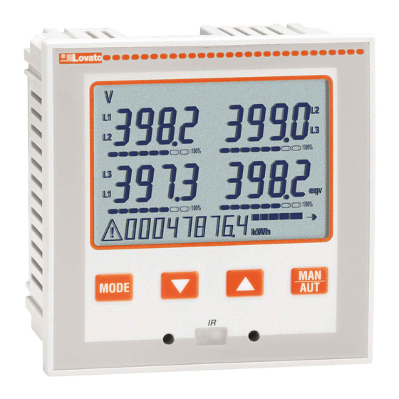
VIEWING OF MEASUREMENTS – The L and M keys allow to scroll the pages of viewed measurements one by one. The page being viewed is shown by the unit of measure in the top part of the display. – Some of the readings may not be shown, depending on the programming and the wiring of the device (for instance, if programmed-wired for a three-phase without neutral system, L-N voltage page is not shown). –... -
Page 4: Display Pages Navigation
DISPLAY PAGES NAVIGATION Phase–Phase voltages IN = Instantaneous value HI = Highest value LO = Lowest value AV = Average value Phase–Neutral voltages IN = Instantaneous value HI = Highest value LO = Lowest value AV = Average value Phase and Neutral currents IN = Instantaneous value HI = Highest value LO = Lowest value... -
Page 5: Expandability
HARMONIC ANALYSIS INDICATION – The DMG600-610 features harmonic analysis up to the 15th order for the following measurements: • phase-to-phase voltages • phase-to-neutral voltages • currents – To activate harmonic analysis, set P02.12 = THD+HAR. – With P02.12 = THD, only the THD of the above measurements is displayed. EXPANDABILITY –... -
Page 6: Main Menu
– PC: You can use the Synergy software to transfer (previously programmed) set-up parameters from the DMG600-610 to the hard drive of the PC and vice versa. – Tablet/Smartphone: Using the dedicated application Lovato Electric Sam1, available for Android and iOS operative systems together with the CX02 dongle, it is possible to program the parameters in a very easy and innovative way. -
Page 7: Parameter Table
Parameter value setting – Pressing the MENU parameter value is saved and you are returned to the previous level, that is the parameter selection. – Press MENU repeatedly to exit and save the setting parameters. The device will reboot. – Alternatively, from within the programming, holding MENU for three consecutive seconds will save the changes and exit directly. –... - Page 8 255.255.255.255 Note: this menu is divided into 2 sections, for comm channels COM1..2. For DMG610, channel COM1 is the built-in RS-485 interface, while COM2 is the evntual second communication port of an EXP module. P07.n.01 – Serial address (node number) for the communication protocol.
- Page 9 P08 - LIMIT TRESHOLDS (LIMn, n=1..8) Default Range P08.n.01 Reference measure OFF- (measures) P08.n.02 Function Max – Min – Min+Max P08.n.03 Upper threshold -9999 - +9999 P08.n.04 Multiplier /100 – x10k P08.n.05 Delay 0.0 – 600.0 P08.n.06 Lower threshold -9999 - +9999 P08.n.07 Multiplier /100 –...
-
Page 10: Alarms
LIMx – ALAx – PULx – REMx – Output linked to the status of the programmed variable. Allows to connect the status of an output to the status of a limit threshold, an alarm, etc. OR LIM – Output linked to the OR-logic of active limit thresholds (DMG610 only). -
Page 11: Cx02 Dongle Usage
CX02 DONGLE USAGE – The CX02 dongle offers WiFi Access point capability for connection to PC, Tablet or smartphones. In addition to this function it also offer the possibility to store and transfer a block of data from/to the DMG600-610. –... -
Page 12: Wiring Diagrams
WIRING DIAGRAMS 3-phase connection whit or without neutral 2-phase connection P01.07 = L1-L2-L3-N L1-L2-L3 P01.07 = L1-N-L2 TA/CT1 TA/CT1 TA/CT2 TA/CT2 TA/CT3 100...440VAC 100...440VAC 110...250VDC 110...250VDC V2 V3 V2 V3 -- - -- - AUX SUPPLY VOLTAGE CURRENT RS485 AUX SUPPLY VOLTAGE CURRENT RS485... -
Page 13: Terminals Position
PC- DMG610 CONNECTION THROUGH RS485 INTERFACE 120R TR A RS485 RS485 DMG610 n°31 DMG610 n°1 Repeat this wiring diagram up to 255 devices TR A TR A TR A B RS485 RS485 DMG610 DMG610 Set as repeater Device addresses n° 31-60 Set as repeater Device addresses n°... -
Page 14: Technical Carachteristics
TECHNICAL CHARACTERISTICS Supply Additional errors Rated voltage Us ‚ 100 - 440V Temperature 0.05%/°K per V, A, W 110 - 250V= Insulation Operating voltage range 90 - 484V Rated insulation voltage Ui 600V 93.5 - 300V= Rated impulse withstand voltage Uimp 9.5kV Frequency 45 - 66Hz... - Page 15 MULTIMETRO DIGITALE Manuale operativo LOVATO ELECTRIC S.P.A. 24020 GORLE (BERGAMO) ITALIA VIA DON E. MAZZA, 12 TEL. 035 4282111 FAX (Nazionale): 035 4282200 FAX (International): +39 035 4282400 DMG600 – DMG610 E-mail info@ ovato lectric.com www. ovato lectric.com WARNING! ATTENZIONE! –...
- Page 16 INTRODUZIONE I multimetri DMG600 e DMG610 sono stati progettati per unire la massima semplicità di utilizzo con una ampia scelta di funzioni avanzate. In esecuzione per montaggio a pannello con dimensioni standard 96x96mm, uniscono il moderno design del frontale alla praticità di montaggio e alla possibilità di espansione sul retro, dove è possibile alloggiare un modulo della serie EXP..Il frontale è dotato della interfaccia ottica a infrarossi che consente la programmazione tramite USB o WiFi.
- Page 17 VISUALIZZAZIONE DELLE MISURE – I tasti L e M consentono di scorrere le pagine di visualizzazione misure una per volta. La pagina attuale è riconoscibile tramite la visualizzazione della unità di misura nella parte alta del display. – Alcune delle misure potrebbero non essere visualizzate in funzione della programmazione e del collegamento dell’apparecchio (ad esempio se programmato per un sistema senza neutro le misure riferite al neutro non vengono visualizzate).
- Page 18 NAVIGAZIONE FRA LE PAGINE DISPLAY Tensioni concatenate IN = Valore istantaneo HI = Valore massimo LO = Valore minimo AV = Valore medio Tensioni di fase IN = Valore istantaneo HI = Valore massimo LO = Valore minimo AV = Valore medio Correnti di fase e neutro IN = Valore istantaneo HI = Valore massimo...
- Page 19 INDICAZIONE ANALISI ARMONICA – Nel DMG100-110 è disponibile l’analisi armonica fino al 15.mo ordine delle seguenti misure: • tensioni concatenate • tensioni di fase • correnti – Per attivare l’analisi armonica, impostare P02.12 = THD+HAR. – Con P02.12 = THD viene visualizzato solo il THD delle misure ESPANDIBILITÀ...
- Page 20 – PC: Mediante il software Synergy è possibile effettuare il trasferimento dei parametri di set-up (precedentemente impostati) da DMG600-610 al disco del PC e viceversa. – Tablet/Smartphone: Utilizzando l’apposita App Lovato Electric Sam1, disponibile per sistemi operativi Android ed iOS in abbinamento ai dongle WiFi CX02 è possibile effettuare la programmazione dei parametri in modo molto semplice ed innovativo.
- Page 21 Impostazione valore del parametro – Premendo MENU il valore del parametro viene memorizzato e si torna al livello precedente, cioè alla selezione parametri. – Premere più volte MENU per uscire dalla impostazione e salvare i parametri. L’apparecchio si reinizializza. – In alternativa, dall’interno della programmazione, tenendo premuto MENU per tre secondi consecutivi, si salvano le modifiche e si esce direttamente. –...
- Page 22 000.000.000.000 – 255.255.255.255 Nota: questo menu è diviso in 2 sezioni, per i canali di comunicazione COM1..2. Per DMG610, COM1 è la porta RS-485 di serie, mentre COM2 è l’eventuale porta di comunicazione aggiuntiva su modulo EXP di espansione. P07.n.01 – Indirizzo seriale (nodo) del protocollo di comunicazione.
- Page 23 P08 - SOGLIE LIMITE (LIMn, n=1..8) Default Range P08.n.01 Misura di riferimento OFF- (misure) P08.n.02 Funzione Max – Min – Min+Max P08.n.03 Soglia superiore -9999 - +9999 P08.n.04 Moltiplicatore /100 – x10k P08.n.05 Ritardo 0.0 – 600.0 P08.n.06 Soglia inferiore -9999 - +9999 P08.n.07 Moltiplicatore...
- Page 24 LIMx – ALAx – PULx – REMx – Uscita abbinata allo stato della variabile programmata. Permette di portare su di una uscita lo stato di una soglia, di un allarme, ecc. OR LIM – Uscita abbinata a OR Logico tra le soglie limite attive (solo per DMG610).
- Page 25 UTILIZZO CHIAVETTA CX02 – La chiavetta (dongle) CX02 oltre a fornire la funzionalità di collegamento WiFi con PC, Tablet o Smartphone ha anche la possibilità di poter memorizzare e trasferire un blocco di dati da e per il DMG600-610. – Inserire l’interfaccia CX02 nell’apposita sede sul fronte del DMG600-610. –...
- Page 26 WIRING DIAGRAMS Connessione trifase con o senza neutro Connessione bifase P01.07 = L1-L2-L3-N L1-L2-L3 P01.07 = L1-N-L2 TA/CT1 TA/CT1 TA/CT2 TA/CT2 TA/CT3 100...440VAC 100...440VAC 110...250VDC 110...250VDC V2 V3 V2 V3 -- - -- - AUX SUPPLY VOLTAGE CURRENT RS485 AUX SUPPLY VOLTAGE CURRENT RS485...
- Page 27 CONNESSIONE PC-DMG610.. MEDIANTE INTERFACCIA RS485 120R TR A RS485 RS485 DMG610 n°31 DMG610 n°1 Repeat this wiring diagram up to 255 devices TR A TR A TR A B RS485 RS485 DMG610 DMG610 Set as repeater Device addresses n° 31-60 Set as repeater Device addresses n°...
- Page 28 CARATTERISTICHE TECNICHE Alimentazione Errori addizionali Tensione nominale Us ‚ 100 - 440V Temperatura 0,05%/°K per V, A, W 110 - 250V= Isolamento Limiti di funzionamento 90 - 484V Tensione nominale d’isolamento Ui 600V 93,5 - 300V= Tensione nomi. di tenuta a impulso Uimp 9,5kV Frequenza 45 - 66Hz...
Need help?
Do you have a question about the DMG610 and is the answer not in the manual?
Questions and answers