Table of Contents
Advertisement
Quick Links
UWAGA!
● Należy dokładnie zapoznać się z poniższa instrukcją przed
instalacją lub używaniem urządzenia.
● By uniknąć uszkodzęń i zagrożenia życia urządzenia
te powinny być instalowane przez wykwalifikowany personel,
i w zgodzie z odpowienimi przepisami.
● Przed pracami serwisowymi, należy odłączyć wszystkie napięcia od wejść
pomiarowych i zasilania pomocniczego oraz zewrzeć zaciski przekładnika
prądowego.
● Produkty zaprezentowane w poniższym dokumencie mogą zostać zmienione
lub ulepszone bez konieczności wcześniejszego informowania o tym.
● Dane techniczne oraz opisy oddają w jak najdokładniejszy sposób posiadaną
przez nas wiedzę, jednak nie bierzemy odpowiedzialności za ewentualne błędy,
braki oraz sytuacje awaryjne.
● W układzie należy zamontować rozłącznik (wyłącznik), który musi znajdować
się niedaleko urządzenia i być łatwo dostępny dla operatora. Musi spełniać wymogi
następujących norm: IEC/ EN 61010-1 § 6.12.2.1.
● Należy czyścić urządzenie delikatną suchą szmatką, nie należy używać środków
ściernych, płynnych detergentów lub rozpuszczalników.
Spis treści
Nawigacja po stronach
Trendy graficzne
Moduły rozszerzeń
Progi limitów
Logika Boole'a
Zmienne kontrolowane zdalnie
Funkcja pamięci zdarzeń
Ustawienia parametrów (setup)
Tabela parametrów
Menu komend
Test okablowania
Dane techniczne
Instalacja
Schematy podłączeń
Rozmieszczenie zacisków
Wymiary mechaniczne
Doc: I272PLGB0710_DMG800
PL
DMG800
Miernik cyfrowy
INSTRUKCJA OBSŁUGI
Strona
2
2
2
3
4
5
5
6
6
6
6
7
7
8
8
9
9
10
10
11
12
12
13
13
13
14
15
16
21
21
23
24
25
26
26
DMG800
Digital multimeter
INSTRUCTIONS MANUAL
WARNING!
Carefully read the manual before the installation or use.
This equipment is to be installed by qualified personnel,
complying to current standards, to avoid damages or safety
hazards.
● Before any maintenance operation on the device, remove all the voltages
from measuring and supply inputs and short-circuit the CT input terminals.
● Products illustrated herein are subject to alteration and changes without prior
notice.
● Technical data and descriptions in the documentation are accurate, to the best
of our knowledge, but no liabilities for errors, omissions or contingencies arising
there from are accepted.
● A circuit breaker must be included in the electrical installation of the building.
It must be installed close by the equipment and within easy reach of the operator.
It must be marked as the disconnecting device of the equipment:
IEC /EN 61010-1 § 6.12.2.1.
●
Clean the instrument with a soft dry cloth; do not use abrasives, liquid
detergents or solvents.
Index
Introduction
Descriptio
Keyboard functions
Measurement viewing
Table of display pages
Display page navigation
Harmonic analysis page
Waveform page
Energy meters page
Hour counters page
Trend graph page
Counters page
User pages
Main menu
Password access
Settings lock
Expandability
Additional resources
Communication channels
Inputs, outputs, internal variables, counters
Boolean logic
Alarms
Tariffs
Setting of parameters (setup)
Table of parameters
Commands menu
Wiring test
Technical characteristics
Wiring diagrams
Terminal arrangement
Mechanical dimensions
09/07/2010
Page
2
2
2
3
4
5
5
6
6
6
6
7
7
8
8
9
9
10
10
11
12
12
13
13
13
14
15
16
21
21
23
24
25
26
26
str. 1 / 26
Advertisement
Table of Contents

Subscribe to Our Youtube Channel
Related Manuals for LOVATO ELECTRIC DMG800L01


Summary of Contents for LOVATO ELECTRIC DMG800L01
-
Page 1: Table Of Contents
DMG800 DMG800 Miernik cyfrowy Digital multimeter INSTRUKCJA OBSŁUGI INSTRUCTIONS MANUAL UWAGA! WARNING! ● Należy dokładnie zapoznać się z poniższa instrukcją przed Carefully read the manual before the installation or use. instalacją lub używaniem urządzenia. This equipment is to be installed by qualified personnel, ●... -
Page 2: Wprowadzenie
Wprowadzenie Introduction Miernik DMG800 został tak zaprojektowany by połączyć maksymalną The DMG800 multimeter has been designed to combine the maximum łatwość działania z szerokim wyborem zaawansowanych funkcji. Poza possible easiness of operation together with a wide choice of advanced obudową do montażu tablicowego 96x96mm, DMG800 posiada functions. -
Page 3: Wizualizacja Odczytów
Wizualizacja odczytów Viewing of measurements Przyciski ▲i ▼pozwalają na przemieszczanie się pomiędzy stronami The ▲and ▼keys allow to scroll the pages of viewed measurements wizualizacji odczytów, jedna po drugiej. Zawartość aktualnie one by one. The page being viewed is written in the title bar. wyświetlanej podstrony opisana jest na pasku, u góry strony. -
Page 4: Tabela Wyświetlanych Stron
Tabela wyświetlanych stron Table of display pages Wybór przyciskami ▲i ▼ Wybór przyciskiem Selection with ▲and ▼ Selection with STRONA PODSTRONA PAGES SUB-PAGES NAPIĘCIA MIĘDZYFAZOWE PHASE-TO-PHASE VOLTAGES V(L1-L2), V(L2-L3), V(L3-L1), V(LL)EQV V(L1-L2), V(L2-L3), V(L3-L1), V(LL)EQV NAPIĘCIA FAZOWE PHASE-TO-NEUTRAL VOLTAGES V(L1-N), V(L2-N), V(L3-N), V(L-N)EQV V(L1-N), V(L2-N), V(L3-N), V(L-N)EQV PRĄDY FAZOWE I PRZEWODU N... -
Page 5: Analiza Harmonicznych
Nawigacja po stronach Display pages navigation Napięcia międzyfazowe Phase–Phase voltages IN = Wart. chwilowa HI = Wart. maksymalna LO = Wart. minimalna AV = Wart. średnia GR = Wykres belkowy IN = Instantaneous value HI = Highest value LO = Lowest value AV = Average value GR = Graphic bars... -
Page 6: Przebiegi
Przebiegi Waveform page Na tej stronie wyświetlany jest graficzny obraz przebiegu napięcia This page graphically views the waveform of the voltage and current i prądu, odczytywanego przez DMG800. signals read by the DMG800. Możliwe jest wyświetlenie jednej fazy w danym momencie, wyboru ... -
Page 7: Liczniki
Dane o poborze zostają utracone kiedy zasilanie pomocnicze urządzenia The consumption data is lost when auxiliary power is removed from the zaniknie lub kiedy zmieniamy ustawienia. DMG device or when the settings in the setup menu are changed. ... -
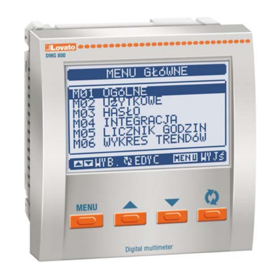
Page 8: Menu Główne
Menu główne Main menu Menu główne składa się z grupy ikon graficznych (skróty) które The main menu is made up of a group of graphic icons (shortcuts) that umożliwiają szybki dostęp do pomiarów i ustawień. allow rapid access to measurements and settings. ... -
Page 9: Blokada Ustawień
By wyjść z ekranu ustawień hasła należy wcisnąć przycisk MENU. To quit the password entry screen press MENU key. Blokada ustawień Settings Lock • Na mierniku DMG800 umieszczone zostały dwa przłączniki typu DIP, • On the DMG800 there are two DIP switches that are used to lock które używane są... -
Page 10: Dodatkowe Zasoby
UWAGA! WARNING! ● Kiedy zainstalowano moduł EXP... na mierniku, When the EXP.. module is installed on a DMG series koniecznie trzeba zainstalować osłonę ochronną zacisków multimeter, it is mandatory to install the sealable dostarczoną wraz z miernikiem. terminal block covers supplied with the multimeter ... -
Page 11: Wejścia, Wyjścia, Wewnętrzne Zmienne, Liczniki
typami komunikacji: Ethernet i RS485, jako pomost łączący inne mierniki both an Ethernet port and a RS485 port, the acts as a bridge over other DMG wyposażone tylko w RS485; umożliwia to otrzymanie bardziej DMGs equipped with RS485 only, in order to achieve a more ekonomicznej wersji konfiguracji (tylko jeden port Ethernet). - Page 12 Progi limitów (LIM) Limit thresholds (LIM) Progi limitów LIMn są wewnętrznymi zmiennymi, których status zależy The LIMn thresholds are internal variables whose status depends on od przekroczenia limitów pomiarów zdefiniowanych przez użytkownika the out-of-limits of one particular measurement set by the user (e.g. (przykład: całkowita moc czynna większa niż...
-
Page 13: Alarmy
Zmienne kontrolowane zdalnie (REM) Remote-controlled variables (REM) Miernik DMG800 posiada możliwość zarządzania 8 zmiennymi, The DMG800 can manage up to 8 remote-controlled variables kontrolowanymi zdalnie (REM1…REM8). (REM1…REM8). Status tych zmiennych może być modyfikowany przez użytkownika Those are variables which status can be modified by the user through poprzez protokoły komunikacyjne, a same zmienne mogą... -
Page 14: Data Loger Function
zmieni się status wyboru wejścia. inputs changes. Odczyty dla poszczególnych taryf, każda z 5 licznikami (energia czynna The tariffs, each with 5 meters (active energy imported/exported, pobrana/oddana, bierna pobrana/oddana, pozorna) są pokazane reactive imported/exported, apparent) are shown on a dedicated page, na dedykowanej stronie, zaraz za ekranem liczników energii following the total-partial energy screen. -
Page 15: Installation
Ustawianie parametrów (setup) Parameter setting (setup) Po pojawieniu się standardowej wizualizacji, należy wcisnąć przycisk With normal viewing, press MENU to recall the General menu, then MENU by przywołać menu główne, następnie wybrać ikonę select icon and press to open the setup menu screen. i wcisnąć... - Page 16 na której pokazny jest zakres, wartosci minimalne i maksymalne, bar that shows the setting range, the maximum and minimum values, poprzednie ustawienia i wartości fabryczne. the previous setting and the factory default. Wciskając jednocześnie przyciski ▲i ▼ustawiamy wartości domyślne. ...
- Page 17 P03.01 – Jeśli ustawiony na OFF, zarządzanie hasłem jest wyłączone a dostęp P03.01 – If set to OFF, password management is disabled and the access to do ustawień parametrów i menu komend nieograniczony. setup parameters and command menu is allowed. P03.02 –...
- Page 18 P07.n.04 Bity Stop P07.n.04 Stop bits P07.n.05 Protokoły Modbus Modbus RTU P07.n.05 Protocol Modbus Modbus RTU Modbus ASCII Modbus ASCII P07.n.06 Adres IP 000.000. 000.000.000.000 - P07.n.06 IP Address 000.000.000 000.000.000.000 - 000.000 255.255.255.255 .000 255.255.255.255 P07.n.07 Podmaska sieci 000.000. 000.000.000.000 - P07.n.07 Subnet mask 000.000.000...
- Page 19 P10.n.06 Jednostka pomiaru (tekst – 6 znaków) P10.n.06 Unit of measure (Text – 6 chars) P10.n.07 Źródło kasowania OFF-ON-INPx-LIMx-BOOx P10.n.07 Reset source OFF-ON-INPx-LIMx-BOOx P10.n.08 Numer kanału (x) 1-16 P10.n.08 Channel number (x) 1-16 Uwaga: To menu jest podzielone na 4 części, każda dla jednego licznika CNT1..4 Note: this menu is divided into 4 sections, for counters CNT1..4 P010.n.01 = Sygnał...
- Page 20 M14 – WYJŚCIA Jed. Domyśl. Zakres M14 – OUTPUTS Default Range (OUTn, n=1..8) (OUTn, n=1..8) P14.n.01 Funkcja wyjścia OFF-ON-SEQ-LIMx- P14.n.01 Output function OFF-ON-SEQ- BOOx-ALAx-PULx- LIMx-BOOx-ALAx- REMx PULx-REMx P14.n.02 Numer kanału (x) 1 – 8 P14.n.02 Channel number (x) 1 – 8 P14.n.03 Status bezczynny OFF-ON...
- Page 21 Uwaga: to menu zostało podzielone na 8 części, każda dla jednego z wyjść Note: this menu is divided into 8 sections, for analog outputs AOU1...AOU8 analogowych AOU1…AOU8 P17.n.01 = Opisuje typ czujnika analogowego podłączonego do wyjścia. W zależności P17.n.01 = Defines the type of the analog sensor connected to analog output. od wyboru, dany czujnik musi być...
- Page 22 By wykonać test, należy wejść do menu komend i wybrać odpowiednią To launch test execution, enter command menu and select the komendę. required command per commands menu instructions. Przeprowadzenie testu umożliwia sprawdzenie poniższych punktów: The test allows to verify the following points: Odczyty z trzech faz Reading of the three phases Kolejność...
- Page 23 Dane techniczne Technical characteristics Zasilanie pomocnicze Auxiliary supply Napięcie znamionowe Us (1) 100 - 440V~ Rated voltage Us (1) 100 - 440V~ 110 - 250V= 110 - 250V= Zakres napięcia pracy 90 - 484V~ Operating voltage range 90 - 484V~ 93,5 - 300V= 93,5 - 300V= Częstotliwość...
- Page 24 Instalacja Installation • Miernik DMG800 został zaprojektowany do montażu tablicowego • The DMG800 is designed for flush-mount installation according to IEC zgodnego z IEC 61554. 61554. • Wkładając urządzenie do otworu montażowego, należy upewnić się, • Insert the device into the panel hole, making sure that the gasket is że uszczelka jest właściwie umieszczona pomiędzy panelem a ramką...
- Page 25 Schematy połączeń Wiring diagrams Podłączenie 3 fazowe z przewodem neutralnym lub bez Podłączenie 2 fazowe 3-phase connection whit or without neutral 2-phase connection P01.07 = L1-L2-L3-N L1-L2-L3 P01.07 = L1-N-L2 100...440VAC 100...440VAC 110...250VDC 110...250VDC V3 VN S1 S2 V3 VN S1 S2 AUX SUPPLY AUX SUPPLY...
- Page 26 UWAGI NOTES Zalecane bezpieczniki: 1. Recommended fuses: Zasilanie pomocnicze: 1A, szybki Aux supply: 1Amp. fast Wejścia pomiarowe napięcia: 1A, szybki Voltage measure inputs: 1Amp. fast 2. Zaciski S2 są połączone wewnątrz. 2. S2 terminals are internally interconnected. Rozmieszczenie zacisków i wymiary mechaniczne Terminals position and mechanical dimensions A1/- A2/+...
Need help?
Do you have a question about the DMG800L01 and is the answer not in the manual?
Questions and answers