LOVATO ELECTRIC DMG200 Instruction Manual
Hide thumbs
Also See for DMG200:
- Instruction manual (15 pages) ,
- Instruction manual (37 pages) ,
- Instruction manual (37 pages)
Table of Contents
Advertisement
Quick Links
UWAGA!
● NaleŜy dokładnie zapoznać się z poniŜsza instrukcją przed
instalacją lub uŜywaniem urządzenia.
● By uniknąć uszkodzeń i zagroŜenia Ŝycia urządzenia
te powinny być instalowane przez wykwalifikowany personel,
i w zgodzie z odpowienimi przepisami.
● Przed pracami serwisowymi, naleŜy odłączyć wszystkie napięcia od wejść
pomiarowych i zasilania pomocniczego oraz zewrzeć zaciski przekładnika
prądowego.
● Produkty zaprezentowane w poniŜszym dokumencie mogą zostać zmienione
lub ulepszone bez konieczności wcześniejszego informowania o tym.
● Dane techniczne oraz opisy oddają w jak najdokładniejszy sposób posiadaną
przez nas wiedzę, jednak nie bierzemy odpowiedzialności za ewentualne błędy,
braki oraz sytuacje awaryjne.
● W układzie naleŜy zamontować rozłącznik (wyłącznik), który musi znajdować
się niedaleko urządzenia i być łatwo dostępny dla operatora. Musi spełniać wymogi
następujących norm: IEC/ EN 61010-1 § 6.12.2.1.
● NaleŜy umieszczać urządzenie w obudowie lub szafie o minimalnym stopniu
ochrony IP40.
● NaleŜy czyścić urządzenie delikatną suchą szmatką, nie naleŜy uŜywać środków
ściernych, płynnych detergentów lub rozpuszczalników.
Spis treści
Doc: I269IGBDFE0310_DMG200_DMG210
PL
DMG200
DMG210
Miernik cyfrowy
INSTRUKCJA OBSŁUGI
Strona
2
2
2
2
3
4
4
5
6
8
8
8
9
9
10
11
12
12
12
DMG200
DMG210
Digital multimeter
INSTRUCTIONS MANUAL
WARNING!
• Carefully read the manual before the installation or use.
• This equipment is to be installed by qualified personnel,
complying to current standards, to avoid damages or safety
hazards.
● Before any maintenance operation on the device, remove all the voltages from
measuring and supply inputs and short-circuit the CT input terminals.
● Products illustrated herein are subject to alteration and changes without prior
notice.
● Technical data and descriptions in the documentation are accurate, to the best
of our knowledge, but no liabilities for errors, omissions or contingencies arising
therefrom are accepted.
● A circuit breaker must be included in the electrical installation of the building. It
must be installed close by the equipment and within easy reach of the operator.
It must be marked as the disconnecting device of the equipment:
IEC /EN 61010-1 § 6.12.2.1.
● Fit the instrument in an enclosure or cabinet with minimum IP40 degree
protection.
● Clean the instrument with a soft dry cloth; do not use abrasives, liquid
detergents or solvents.
Index
15/04/2009
Page
2
2
2
2
3
4
4
5
6
8
8
8
9
9
10
11
12
12
12
s. 1 / 12
Advertisement
Table of Contents

Related Manuals for LOVATO ELECTRIC DMG200


Summary of Contents for LOVATO ELECTRIC DMG200
-
Page 1: Table Of Contents
DMG200 DMG200 DMG210 DMG210 Miernik cyfrowy Digital multimeter INSTRUKCJA OBSŁUGI INSTRUCTIONS MANUAL UWAGA! WARNING! ● NaleŜy dokładnie zapoznać się z poniŜsza instrukcją przed • Carefully read the manual before the installation or use. instalacją lub uŜywaniem urządzenia. • This equipment is to be installed by qualified personnel, ●... -
Page 2: Wprowadzenie
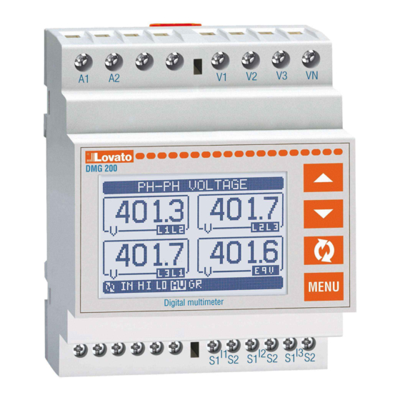
Introduction Mierniki DMG200 i DMG210 zostały tak zaprojektowane by zapewnić The DMG200 and DMG210 multimeters have been designed to join the szeroki wybór funkcji i maksymalna prostotę działania i pracy. Poza maximum possible easiness of operation together with a wide choice of kompaktową... -
Page 3: Tabela Wyświetlanych Stron
Strona tytułowa Title bar Pomiar Wskaźnik fazy Measure Phase indication Jednostka Unit of measure pomiaru Sub-page Wskaźnik indication podstrony Tabela podstron wyświetlacza Display pages table Wybór przyciskami ▲i ▼ Wybór przyciskiem Selection with ▲and ▼ Selection with STRONY PODSTRONY PAGES SUB-PAGES NAPIĘCIA MIĘDZYFAZOWE PHASE-TO-PHASE VOLTAGES... -
Page 4: Menu Główne
Prądy fazowe i N Phase–Neutral currents … (kontynuacja) IN = Wartość chwilowa HI = Wartość maks. LO = Wartość min. AV = Wartość średnia MD = Maks. zapotrzeb. (continues) IN = Instantaneous value HI = Highest value LO = Lowest value AV = Average value MD = Max demand ▲... -
Page 5: Ustawianie Parametrów (Setup)
• Przyciskiem potwierdzamy wybrana cyfrę i przemieszczamy • Key confirms the digit and moves to the next. się do następnej. • Po wprowadzeniu numerycznego kodu, przechodzimy do ikony • Enter numeric code, then move on the key icon. z kluczykiem. •... -
Page 6: Tabela Parametrów
P01.01 – CT primary winding rated current. P01.02 – Prąd znamionowy strony wtórnej. Dla DMG200 i DMG210 - stały 5A. P01.02 – CT secondary winding rated current. For DMG200 and 210 fixed to 5A. P01.03 - Napięcie znamionowe linii. Gdy ustawione na tryb AUT, miernik P01.03 –... - Page 7 P04.03 Czas integracji prądu 1-60min P04.03 Current int. Time 1-60min P04.01 – Wybór metody uśredniania przy kalkulacji odczytów. P04.01 – Selection of average reading calculation method: Stała = Pomiary uśredniane są przez ustawiony czas. Za kaŜdym razem gdy upłynie Fixed = Readings are integrated for the set time. Every time the integration time czas uśredniania, wartość...
-
Page 8: Liczniki Energii
Liczniki energii Energy meters page • Na stronie licznków energii moŜemy zobaczyć jednocześnie: • The Energy meter page shows the following meters simultaneously: energię czynną, pobraną i oddaną active energy Imported and exported energię bierną, pobraną i oddaną (indukcyjną/pojemnościową) reactive energy imported and exported (inductive / capacitive) energię... -
Page 9: Menu Komend
PoniŜej znajduje się tabela funkcji dostępnych w menu komend, The following table lists the functions available in the command menu, • • w podziale na wymagany poziom dostępu. divided by the access level required. POZIOM ACCESS KOMENDA OPIS Cod. COMMAND DESCRIPTION DOSTĘPU LEVEL... -
Page 10: Dane Techniczne
93,5 - 300V= 93,5 - 300V= Częstotliwość 45 - 66Hz Frequency 45 - 66Hz Pobór mocy / rozproszenie mocy DMG200: 3,2VA 1,1W Power consumption/dissipation DMG200: 3.2VA 1.1W DMG210: 4VA 1,4W DMG210: 4VA 1.4W Odporność na mikrowyłączenia ≥50ms Immunity time for microbreakings ≥50ms... -
Page 11: Schematy Połączeń
V3 VN S1 S2 AUX SUPPLY VOLTAGE CURRENT DMG200-DMG210-DMG300 Podłączenie 3 fazowe w układzie ARONA, bez przewodu neutralnego Podłączenie 3 fazowe w układzie ARONA, bez przewodu neutralnego ARON connection 3 phase without neutral ARON connection 3 phase without neutral P01.07 = L1-L2-L3 P01.07 = L1-L2-L3... -
Page 12: Podłączenie Pc-Dmg210 Przez Rs485
UWAGA NOTE Zalecane bezpieczniki: Recommended fuses: Zasilanie pomocnicze: 1A, szybki Aux supply: 1Amp. fast Wejścia pomiarowe napięcia: 1A, szybki Measure inputs voltage: 1Amp. fast Podłączenie PC-DMG210.. przez RS485 PC-DMG210 connection through RS485 interface TR A RS485 RS485 DMG210 n°31 DMG210 n°1 Repeat this wiring diagram up to 255 devices TR A B...
Need help?
Do you have a question about the DMG200 and is the answer not in the manual?
Questions and answers