LOVATO ELECTRIC DMG600 Instruction Manual
Hide thumbs
Also See for DMG600:
- Instruction manual (20 pages) ,
- Installation manual (9 pages) ,
- Instruction manual (20 pages)
Table of Contents
Advertisement
Quick Links
Download this manual
See also:
Installation Manual
ACHTUNG!
● Dieses Handbuch vor Gebrauch und Installation aufmerksam lesen.
● Zur Vermeidung von Personen- und Sachschäden dürfen diese Geräte
nur von qualifiziertem Fachpersonal und unter Befolgung der einschlägigen
Vorschriften installiert werden.
● Vor jedem Eingriff am Instrument die Spannungszufuhr zu den Messeingängen trennen und
die Stromwandler kurzschließen.
● Bei zweckwidrigem Gebrauch der Vorrichtung übernimmt der Hersteller keine Haftung für die
elektrische Sicherheit.
● Die in dieser Broschüre beschriebenen Produkte können jederzeit weiterentwickelt und
geändert werden. Die im Katalog enthaltenen Beschreibungen und Daten sind daher
unverbindlich und ohne Gewähr.
● In die elektrische Anlage des Gebäudes ist ein Ausschalter oder Trennschalter einzubauen.
Dieser muss sich in unmittelbarer Nähe des Geräts befinden und vom Bediener leicht zugänglich
sein. Er muss als Trennvorrichtung für das Gerät gekennzeichnet sein: IEC/ EN 61010-1
§ 6.11.2.
● Das Instrument mit einem weichen Tuch reinigen, keine Scheuermittel, Flüssigreiniger oder
Lösungsmittel verwenden.
Inhalt
Vorwort
Die Multimeter DMG600 und DMG610 wurden entwickelt, um maximale
Benutzerfreundlichkeit mit einer Vielzahl von erweiterten Funktionen zu
vereinen. Ausgelegt für die Aufbaumontage mit Standardmaßen 96x96mm
vereinen sie das moderne Design der Frontblende mit einer praktischen
Montage und der Möglichkeit der Erweiterung an der Rückseite, wo ein
Modul der Serie EXP... eingesetzt werden kann. Die Frontblende ist mit
einer optischen Schnittstelle ausgestattet, die zur Programmierung über
USB oder WiFi dient.
Das LCD-Display mit Hintergrundbeleuchtung bietet eine
leichtverständliche und intuitive Benutzeroberfläche. DMG610 verfügt
außerdem über eine isolierte Kommunikationsschnittstelle RS-485 mit
Modbus-Protokoll für die Überwachung.
Doc: I411DGB04_15.doc
DE
DMG600 - DMG610
Digitalmultimeter
BETRIEBSANLEITUNG
Seite
1
2
2
2
3
4
5
5
5
6
6
6
7
7
8
8
8
13
14
14
15
15
16
17
18
19
19
20
DMG600 - DMG610
Digital multimeter
INSTRUCTIONS MANUAL
WARNING!
Carefully read the manual before the installation or use.
This equipment is to be installed by qualified personnel, complying to
current standards, to avoid damages or safety hazards.
● Before any maintenance operation on the device, remove all the voltages from measuring
and supply inputs and short-circuit the CT input terminals.
● Products illustrated herein are subject to alteration and changes without prior notice.
● Technical data and descriptions in the documentation are accurate, to the best of our
knowledge, but no liabilities for errors, omissions or contingencies arising there from are
accepted.
● A circuit breaker must be included in the electrical installation of the building. It must be
installed close by the equipment and within easy reach of the operator.
It must be marked as the disconnecting device of the equipment:
IEC /EN 61010-1 § 6.11.2.
● Clean the instrument with a soft dry cloth; do not use abrasives, liquid detergents or solvents
Index
Installation
Introduction
The DMG600 and DMG610 multimeters have been designed to combine
the maximum possible easiness of operation together with a wide choice
of advanced functions. The flush-mount 96x96mm housing joins the
modern design of the front panel with the tool-less mounting of the device
body and the expansion capability of the rear panel, where it is possible to
mount plug-in one module of EXP... series. The front panel is equipped
with an infrared optical interface that allows programming through USB or
WiFi dongles. The backlighted LCD display offers a user-friendly interface.
Model DMG610 is also provided with a isolated RS-485 interface with
Modbus protocol to consent remote supervision.
21/04/2015
.
Page
1
2
2
2
3
4
5
5
5
6
6
6
7
7
8
8
8
13
14
14
15
15
16
17
18
19
19
20
p. 1 / 20
Advertisement
Table of Contents

Related Manuals for LOVATO ELECTRIC DMG600


Summary of Contents for LOVATO ELECTRIC DMG600
-
Page 1: Table Of Contents
Vorwort Introduction Die Multimeter DMG600 und DMG610 wurden entwickelt, um maximale The DMG600 and DMG610 multimeters have been designed to combine Benutzerfreundlichkeit mit einer Vielzahl von erweiterten Funktionen zu the maximum possible easiness of operation together with a wide choice vereinen. -
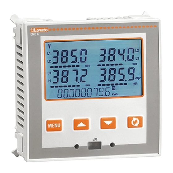
Page 2: Beschreibung
Backlit LCD screen. Ausführungen: Versions: DMG600 - Basisausführung, erweiterbar. DMG600 – base version, expandable. DMG610 - erweiterbar mit integrierter Schnittstelle RS485. DMG610 – expandable, with built-in RS485 interface. 4 Navigationstasten für Funktionen und Einstellungen. 4 navigation keys for function and settings. -
Page 3: Anzeige Der Messungen
Anzeige der Messungen Viewing of measurements Mit den Tasten ▲und ▼können die Seiten mit den Messungen The ▲and ▼keys allow to scroll the pages of viewed measurements nacheinander angezeigt werden. Die aktuelle Seite ist an der Anzeige one by one. The page being viewed is shown by the unit of measure in der Maßeinheit im oberen Displaybereich zu erkennen. -
Page 4: Tabelle Der Display-Seiten
Tabelle der Display-Seiten Table of display pages Auswahl mit ▲und ▼ Auswahl mit Selection with ▲and ▼ Selection with UNTERSEITEN SEITEN PAGES SUB-PAGES VERKETTETE SPANNUNGEN PHASE-TO-PHASE VOLTAGES V(L1-L2), V(L2-L3), V(L3-L1), V(LL)EQV V(L1-L2), V(L2-L3), V(L3-L1), V(LL)EQV PHASENSPANNUNGEN PHASE-TO-NEUTRAL VOLTAGES V(L1-N), V(L2-N), V(L3-N), V(L-N)EQV V(L1-N), V(L2-N), V(L3-N), V(L-N)EQV PHASEN- UND... -
Page 5: Navigation Durch Die Displayseiten
Indication of hour meter Wenn der Zähler aktiviert ist (siehe Menü P05), zeigt das Multimeter If the hour meter is enabled (see menu P05) the DMG600-610 displays DMG600-610 die Stundenzähler-Seite mit dem unten abgebildeten the hour meter page with the format shown in the following picture:... -
Page 6: Statusanzeige Grenzwerte (Limn)
Anzeige Oberschwingungsanalyse Harmonic analysis indication Im DMG600-610 ist die Oberschwingungsanalyse bis zur 15. Oberwelle The DMG600-610 features harmonic analysis up to the 15th order for der folgenden Messungen verfügbar: the following measurements: verkettete Spannungen phase-to-phase voltages ... -
Page 7: Ir Programmierschnittstelle
IR programming port Die Konfiguration der Parameter des DMG600-610 ist über die The parameters of the DMG600-610 can be configured through the frontseitige optische Schnittstelle, über den Programmier-Stick IR-USB front optical port, using the IR-USB code CX01 programming dongle, Code CX01 oder über den Stick IR-WiFi Code CX02 möglich. -
Page 8: Hauptmenü
Hauptmenü Main menu Zum Öffnen des Hauptmenüs: To access the main menu: Die Taste MENU drücken. Es öffnet sich das Hauptmenü (siehe Press the MENU button. The main menu is displayed (see figure) with Abbildung) mit den möglichen Optionen: the following possible choices: o SET –... - Page 9 Es wird daran erinnert, dass nur für die über Tastatur änderbaren DMG600-610. This data can be restored when necessary in the work Parameter im EEprom-Speicher des DMG600-610 eine memory.
-
Page 10: Parametertabelle
Parametertabelle Parameter table Die nachfolgende Tabelle enthält alle verfügbaren Below are listed all the programming parameters in tabular form. For each Programmierparameter. Für jeden Parameter sind der mögliche parameter are indicated the possible setting range and factory default, as Wertebereich, die Werkseinstellung und eine Erklärung der well as a brief explanation of the function of the parameter. - Page 11 P03 – PASSWORT M.E. Default Wertebereich P03 – PASSWORD Default Range P03.01 Passwortschutz OFF-ON P03.01 Enable passwords OFF-ON P03.02 Password Benutzerebene 1000 0-9999 P03.02 User level password 1000 0-9999 P03.03 Password erweiterte Ebene 2000 0-9999 P03.03 Advanced level password 2000 0-9999 P03.01 –...
- Page 12 P07.n.06 IP-Adresse 000.000.000. 000.000.000.000 - P07.n.07 Subnet mask 000.000.000. 000.000.000.000 - 255.255.255.255 255.255.255.255 P07.n.07 Subnetzmaske 000.000.000. 000.000.000.000 - P07.n.08 IP port 1001 0-32000 255.255.255.255 P07.n.09 Client/Server Server Client P07.n.08 IP-Port 1001 0-32000 Server P07.n.09 Client/Server Server Client P07.n.10 Remote IP address 000.000.000.
-
Page 13: Alarme
P11 – IMPULSE Default Wertebereich P11 – PULSES Default Range (PULn, n=1..2) (PULn, n=1..2) P11.n.01 Quellenmessung OFF, kWh+, kWh-, P11.n.01 Source measurement OFF, kWh+, kWh-, kvarh+, kvarh-, kVAh kvarh+, kvarh-, kVAh P11.n.02 Einheit der Zählung 10/100/1k/10k P11.n.02 Count unit 10/100/1k/10k P11.n.03 Impulsdauer 0.01-1.00 P11.n.03 Pulse duration... -
Page 14: Befehlsmenü
Befehlsmenü Commands menu Das Befehlsmenü dient zur Ausführung gelegentlicher Vorgänge, wie The commands menu allows executing some occasional operations like das Rücksetzen von Messungen, Zählern, Alarmen usw. reading peaks resetting, counters clearing, alarm reset, etc. Wenn das Passwort für die erweiterte Ebene eingegeben wurde, ... -
Page 15: Verwendung Des Programmier-Sticks Cx01
Press 3 times consecutively and fast the dongle button. Warten, bis die LED orange wird und blinkt. At this point the display of the DMG600-610 shows the first of the 6 possible 3 Mal schnell nacheinander die Taste des CX02 drücken. -
Page 16: Installation
Installation Installation DMG600-610 ist für die Unterputzmontage bestimmt. Bei korrektem DMG600-610 is designed for flush-mount installation. With proper mounting, it Einbau wird Schutzart IP54 an der Vorderseite garantiert. guarantees IP54 front protection. Jeden der vier Clips von der Innenseite der BLK-Anlage in eine der zwei ... -
Page 17: Anschlusspläne
Anschlusspläne Wiring diagrams Dreiphasenschaltung mit oder ohne Neutralleiter Zweiphasenschaltung 3-phase connection whit or without neutral 2-phase connection P01.07 = L1-L2-L3-N L1-L2-L3 P01.07 = L1-N-L2 Einphasenschaltung Symmetrisierte Dreiphasenschaltung mit oder ohne Neutralleiter Single-phase connection Balanced 3-phase connection whit or without neutral P01.07 = L1-N P01.07 = L1-L2-L3-N-BIL L1-L2-L3-BIL Aronschaltung 3 Phasen ohne Neutralleiter... -
Page 18: Klemmenanordnung
Versorgungsspannung 220…240VAC 10% oder 110…120VAC auf Anfrage RS-232/RS-485 opto-isolated converter drive, 38,400 Baud-rate max, automatic or manual TRANSMIT line supervision, 220…240VAC 10% supply (possible 110…120VAC on request). Klemmenanordnung Terminals position DMG600 DMG610 Doc: I411DGB04_15.doc 21/04/2015 p. 18 / 20... -
Page 19: Mechanische Abmessungen Und Bohrung Der Platte (Mm)
Mechanische Abmessungen und Bohrung der Platte (mm) Mechanical dimensions and front panel cutout (mm) Technische Merkmale Technical characteristics Stromversorgung Supply Nennspannung Us 100 - 440V~ Rated voltage Us 100 - 440V~ 110 - 250V= 110 - 250V= Betriebsgrenzen 90 - 484V~ Operating voltage range 90 - 484V~... -
Page 20: Chronik Der Revisionen Der Betriebsanleitung
Zulassungen und Konformität Certifications and compliance cULus Anhängig cULus Pending Konform mit den Normen IEC/EN 61010-1, IEC/EN 61000-6-2 Reference standards IEC/EN 61010-1, IEC/EN 61000-6-2 IEC/ EN 61000-6-4 IEC/ EN 61000-6-4 UL61010-1 und CSA C22.2-N°61010-1 UL61010-1 and CSA C22.2-N°61010-1 Von einem System mit Spannung Phase-Neutralleiter ≤300V entnommene ...
Need help?
Do you have a question about the DMG600 and is the answer not in the manual?
Questions and answers