LOVATO ELECTRIC DMG210 Instruction Manual
Hide thumbs
Also See for DMG210:
- Instruction manual (15 pages) ,
- Instruction manual (12 pages) ,
- Instruction manual (37 pages)
Table of Contents
Advertisement
Available languages
Available languages
LOVATO ELECTRIC S.P.A.
24020 GORLE (BERGAMO) ITALIA
VIA DON E. MAZZA, 12
TEL. 035 4282111
FAX (Nazionale): 035 4282200
FAX (International): +39 035 4282400
L
E
E-mail info@
ovato
lectric.com
L
E
Web
www.
ovato
lectric.com
The complete operating manual is
downloadable from website
www.lovatoelectric.com
Il manuale operativo completo è
scaricabile dal sito www.lovatoelectric.com
GB
DMG200 - DMG210
D
Available in German at www.LovatoElectric.com/I269D.pdf
PL
Available in Polish at www.LovatoElectric.com/I269PL.pdf
WARNING!
– Carefully read the manual before the installation or use.
– This equipment is to be installed by qualified personnel, complying to current standards, to avoid damages or safety hazards.
– Before any maintenance operation on the device, remove all the voltages from measuring and supply inputs and short-circuit the CT input terminals.
– The manufacturer cannot be held responsible for electrical safety in case of improper use of the equipment.
– Products illustrated herein are subject to alteration and changes without prior notice. Technical data and descriptions in the documentation are accurate, to
the best of our knowledge, but no liabilities for errors, omissions or contingencies arising there from are accepted.
– A circuit breaker must be included in the electrical installation of the building. It must be installed close by the equipment and within easy reach of the operator.
It must be marked as the disconnecting device of the equipment: IEC /EN 61010-1 § 6.11.2.
– Fit the instrument in an enclosure or cabinet with minimum IP40 degree protection.
– Clean the device with a soft dry cloth; do not use abrasives products, liquid detergents or solvents.
INDEX
Introduction . . . . . . . . . . . . . . . . . . . . . . . . . . . . . . . . . . . . . . . . . . . . . . . . . . . . . . . . . . . . . . . . . . . . . . . . . . . . . . . . . . . . . . . . . . . . . . . . . . . . . . . . . . . . . . . . .
Description . . . . . . . . . . . . . . . . . . . . . . . . . . . . . . . . . . . . . . . . . . . . . . . . . . . . . . . . . . . . . . . . . . . . . . . . . . . . . . . . . . . . . . . . . . . . . . . . . . . . . . . . . . . . . . . . . .
Keyboard functions . . . . . . . . . . . . . . . . . . . . . . . . . . . . . . . . . . . . . . . . . . . . . . . . . . . . . . . . . . . . . . . . . . . . . . . . . . . . . . . . . . . . . . . . . . . . . . . . . . . . . . . . . . .
Display of readings . . . . . . . . . . . . . . . . . . . . . . . . . . . . . . . . . . . . . . . . . . . . . . . . . . . . . . . . . . . . . . . . . . . . . . . . . . . . . . . . . . . . . . . . . . . . . . . . . . . . . . . . . . .
Table of display pages . . . . . . . . . . . . . . . . . . . . . . . . . . . . . . . . . . . . . . . . . . . . . . . . . . . . . . . . . . . . . . . . . . . . . . . . . . . . . . . . . . . . . . . . . . . . . . . . . . . . . . . . .
Main menu . . . . . . . . . . . . . . . . . . . . . . . . . . . . . . . . . . . . . . . . . . . . . . . . . . . . . . . . . . . . . . . . . . . . . . . . . . . . . . . . . . . . . . . . . . . . . . . . . . . . . . . . . . . . . . . . . .
Password access . . . . . . . . . . . . . . . . . . . . . . . . . . . . . . . . . . . . . . . . . . . . . . . . . . . . . . . . . . . . . . . . . . . . . . . . . . . . . . . . . . . . . . . . . . . . . . . . . . . . . . . . . . . . .
Parameter setting (setup). . . . . . . . . . . . . . . . . . . . . . . . . . . . . . . . . . . . . . . . . . . . . . . . . . . . . . . . . . . . . . . . . . . . . . . . . . . . . . . . . . . . . . . . . . . . . . . . . . . . . . .
Parameter table . . . . . . . . . . . . . . . . . . . . . . . . . . . . . . . . . . . . . . . . . . . . . . . . . . . . . . . . . . . . . . . . . . . . . . . . . . . . . . . . . . . . . . . . . . . . . . . . . . . . . . . . . . . . . .
Energy meters page . . . . . . . . . . . . . . . . . . . . . . . . . . . . . . . . . . . . . . . . . . . . . . . . . . . . . . . . . . . . . . . . . . . . . . . . . . . . . . . . . . . . . . . . . . . . . . . . . . . . . . . . . . .
Hour counters page . . . . . . . . . . . . . . . . . . . . . . . . . . . . . . . . . . . . . . . . . . . . . . . . . . . . . . . . . . . . . . . . . . . . . . . . . . . . . . . . . . . . . . . . . . . . . . . . . . . . . . . . . . .
Trend graph page . . . . . . . . . . . . . . . . . . . . . . . . . . . . . . . . . . . . . . . . . . . . . . . . . . . . . . . . . . . . . . . . . . . . . . . . . . . . . . . . . . . . . . . . . . . . . . . . . . . . . . . . . . . . .
Commands menu . . . . . . . . . . . . . . . . . . . . . . . . . . . . . . . . . . . . . . . . . . . . . . . . . . . . . . . . . . . . . . . . . . . . . . . . . . . . . . . . . . . . . . . . . . . . . . . . . . . . . . . . . . . . .
Wiring test . . . . . . . . . . . . . . . . . . . . . . . . . . . . . . . . . . . . . . . . . . . . . . . . . . . . . . . . . . . . . . . . . . . . . . . . . . . . . . . . . . . . . . . . . . . . . . . . . . . . . . . . . . . . . . . . . .
Technical characteristics. . . . . . . . . . . . . . . . . . . . . . . . . . . . . . . . . . . . . . . . . . . . . . . . . . . . . . . . . . . . . . . . . . . . . . . . . . . . . . . . . . . . . . . . . . . . . . . . . . . . . . . .
Wiring diagrams. . . . . . . . . . . . . . . . . . . . . . . . . . . . . . . . . . . . . . . . . . . . . . . . . . . . . . . . . . . . . . . . . . . . . . . . . . . . . . . . . . . . . . . . . . . . . . . . . . . . . . . . . . . . . .
PC-DMG210 connection through RS485 interface . . . . . . . . . . . . . . . . . . . . . . . . . . . . . . . . . . . . . . . . . . . . . . . . . . . . . . . . . . . . . . . . . . . . . . . . . . . . . . . . . . .
Terminal arrangement. . . . . . . . . . . . . . . . . . . . . . . . . . . . . . . . . . . . . . . . . . . . . . . . . . . . . . . . . . . . . . . . . . . . . . . . . . . . . . . . . . . . . . . . . . . . . . . . . . . . . . . . . .
Mechanical dimensions . . . . . . . . . . . . . . . . . . . . . . . . . . . . . . . . . . . . . . . . . . . . . . . . . . . . . . . . . . . . . . . . . . . . . . . . . . . . . . . . . . . . . . . . . . . . . . . . . . . . . . . .
INTRODUCTION
The DMG200 and DMG210 multimeters have been designed to join the maximum possible ease of operation together with a wide choice of advanced functions.
Regardless of the compactness of the modular housing (only 4U), the multimeter performance is the same as high-end devices.
The graphic LCD offers user-friendly interface. The rich variety of functions makes the DMG series multimeters the ideal choice for a wide range of applications.
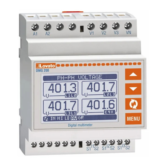
DESCRIPTION
– Modular DIN-rail housing, 4U (72mm wide)
– Graphic LCD display, 128x80 pixels, white backlighting, 4 grey levels
– Membrane keyboard with 4 keys for viewing and setting
– Easy and fast navigation
– Texts for measurements, setup and messages in 5 languages
– Reading of 160 electrical parameters
– DMG210 version with built-in RS485 interface
– True RMS measurements
– Continuous (gapless) sampling
– High accuracy.
KEYBOARD FUNCTIONS
L and M keys - Used to scroll display pages, to select among possible choices, and to modify settings (increment-decrement).
key - Used to move through sub-pages, to confirm a choice, to switch between viewing modes.
MENU key - Used to enter or exit from viewing and setting menus.
DIGITAL MULTIMETER
Instructions manual
CZ
Available in Czech at www.LovatoElectric.com/I269CZ.pdf
RU
Available in Russian at www.LovatoElectric.com/I269RU.pdf
G
B
Page
1
1
1
2
2
3
3
3
4
5
6
6
6
6
7
8
9
9
9
1
Advertisement
Table of Contents

Related Manuals for LOVATO ELECTRIC DMG210


Summary of Contents for LOVATO ELECTRIC DMG210
- Page 1 INTRODUCTION The DMG200 and DMG210 multimeters have been designed to join the maximum possible ease of operation together with a wide choice of advanced functions. Regardless of the compactness of the modular housing (only 4U), the multimeter performance is the same as high-end devices.
-
Page 2: Display Of Readings
DISPLAY OF READINGS – The L and M keys allow to scroll the view pages of readings, one by one. The actual page being viewed is written in the title bar. – Some of the readings may not be shown, depending on the programming and the wiring of the device (for instance, if programmed-wired for a three-phase without neutral system, L-N voltage page is not shown). -
Page 3: Main Menu
– The following table lists the available sub-menus: Code Sub-menu Description GENERAL Rated data of the installation UTILITY Language, backlight, display pages etc. PASSWORD Access codes INTEGRATION Readings integration time HOUR METER Hour counter enable TREND PAGE Trend graph reading and scale COMMUNICATION Communication port parameters (DMG210) -
Page 4: Parameter Table
L1-N P01.01 - CT primary winding rated current. P01.02 - CT secondary winding rated current. DMG200 and DMG210 are fixed at 5A only. P01.03 - Line rated voltage. Leaving at Aut, the multimeter automatically adapts bar-graph full scale. P01.04 - Set to ON if VT are used. If set to OFF, the following two parameters will be ignored. -
Page 5: Energy Meters
Modbus RTU Modbus RTU Modbus ASCII Note: This menu is enabled only for DMG210. P07.01 - Serial address (node number) for the communication protocol. P07.02 - Serial communication speed. P07.03 - Data format. Can be set to 7 bits for ASCII protocol only. -
Page 6: Commands Menu
HOUR COUNTERS PAGE – The Hour counters page shows the following meters simultaneously: • Total hour counter (counts the power-on time of the device) • Partial hour counter. – To clear counters it is necessary to access the commands menu. –... -
Page 7: Technical Characteristics
Conductor cross section (min-max) 0.2-4.0mm (24-12AWG) Current inputs Tightening torque 0.8Nm (7lbin) Rated current Ie Current Input and RS485 (DMG210 only) connections Measuring range 0.010-6A Type of terminal Screw (fixed) Type of input Shunt supplied by an external current transformer... -
Page 8: Wiring Diagrams
WIRING DIAGRAMS 3 phase connection with or without neutral 2 phase connection P01.07 = L1-L2-L3-N L1-L2-L3 P01.07 = L1-N-L2 100...240VAC 100...240VAC 110...250VDC 110...250VDC -- - V2 V3 S1 S2 S1 S2 S1 S2 VOLTAGE CURRENT VOLTAGE CURRENT AUX SUPPLY AUX SUPPLY Single phase connection Balanced 3 phase connection with or without neutral P01.07 = L1-N... -
Page 9: Pc-Dmg210 Connection Through Rs485 Interface
PC-DMG210 CONNECTION THROUGH RS485 INTERFACE Max 1200m Cable 51C4 TR A RS485 Interface converter RS485 RS232/485 DMG210 n°31 DMG210 n°1 Max 1200m Max 1200m Cable 51C4 Repeat this wiring diagram up to 255 devices TR A TR A B SG... -
Page 10: Via Don E. Mazza
INTRODUZIONE I multimetri DMG200 e DMG210 sono stati progettati per unire la massima semplicità di utilizzo con una ampia scelta di funzioni avanzate. Nonostante l’estrema compattezza del contenitore modulare (solo 4U), le prestazioni del multimetro sono le stesse di un apparecchio di alto livello. Il display grafico LCD consente una interfaccia utente intuitiva. -
Page 11: Visualizzazione Delle Misure
VISUALIZZAZIONE DELLE MISURE – I tasti L e M consentono di scorrere le pagine di visualizzazione misure una per volta. La pagina attuale è riconoscibile tramite la barra del titolo. – Alcune delle misure potrebbero non essere visualizzate in funzione della programmazione e del collegamento dell’apparecchio (ad esempio se programmato per un sistema senza neutro le misure riferite al neutro non vengono visualizzate). -
Page 12: Menu Principale
– Nella seguente tabella sono elencati i sottomenu disponibili Cod. Sottomenu Descrizione GENERALE Dati caratteristici dell’impianto UTILITA’ Lingua, luminosità, pagine display ecc. PASSWORD Abilitazione protezione accesso INTEGRAZIONE Tempi di integrazione misure CONTAORE Abilitazione contaore GRAFICO TREND Definizione misura e scala grafico trend COMUNICAZIONE Parametri porta comunicazione (DMG210) - Page 13 P01.01 - Corrente nominale del primario dei TA. P01.02 - Corrente normale del secondario dei TA. Per DMG200 e DMG210 fissa a 5 A. P01.03 - Tensione nominale dell’impianto. Lasciando su Aut il multimetro adegua automaticamente la scala delle barre grafiche.
- Page 14 Modbus RTU Modbus RTU Modbus ASCII Nota: Menu abilitato solo per DMG210. P07.01 - Indirizzo seriale (nodo) del protocollo di comunicazione. P07.02 - Velocità di trasmissione della porta di comunicazione. P07.03 - Formato dati. Impostazioni a 7 bit possibili solo per protocollo ASCII.
-
Page 15: Menu Comandi
PAGINA CONTAORE – Nella pagina contaore vengono visualizzati: • contatore totale (conta il tempo di alimentazione dell’apparecchio) • contaore parziale. – Per l’azzeramento dei contatori è necessario accedere al menu comandi. – La pagina contaore può essere disabilitata completamente se l’abilitazione generale contaore viene impostata su OFF (vedere menu Contaore). PAGINA GRAFICO TREND –... -
Page 16: Caratteristiche Tecniche
0,2-4,0mm (24-12AWG) Ingressi amperometrici Coppia di serraggio morsetti 0,8Nm (7lbin) Corrente nominale Ie Connessioni circuito misura correnti e RS485 (solo DMG210) Campo di misura 0,010-6A Tipo di morsetti A vite (fissi) Tipo di ingresso Shunt alimentati mediante trasformatore di corrente... -
Page 17: Schemi Di Connessione
SCHEMI DI CONNESSIONE Connessione trifase con o senza neutro Connessione bifase P01.07 = L1-L2-L3-N L1-L2-L3 P01.07 = L1-N-L2 100...240VAC 100...240VAC 110...250VDC 110...250VDC -- - V2 V3 S1 S2 S1 S2 S1 S2 VOLTAGE CURRENT VOLTAGE CURRENT AUX SUPPLY AUX SUPPLY Connessione monofase Connessione trifase bilanciata con o senza neutro P01.07 = L1-N... - Page 18 CONNESSIONE PC-DMG210.. MEDIANTE INTERFACCIA RS485 Max 1200m Cable 51C4 TR A RS485 Interface converter RS485 RS232/485 DMG210 n°31 DMG210 n°1 Max 1200m Max 1200m Cable 51C4 Repeat this wiring diagram up to 255 devices TR A TR A B SG...
- Page 19 INTRODUCTION Les multimètres DMG200 et DMG210 sont conçus pour unir la facilité maximale d’utilisation avec un vaste choix de fonctions évoluées. Indépendamment de l’extrême compacté de la boitier modulaire (solo 4U), les performances du multimètre sont les mêmes d’un appareil de haut niveau. L’afficheur à LCD graphique offre une interface facile à...
- Page 20 VISUALISATION DES MESURES – Les touches L et M permettent de défiler entre les pages de affichage mesures, une à une. La page visualisée est indiquée à la barre de titre. – Quelques mesures ne peuvent pas être visualisées en fonction de la programmation et de la connexion de l’appareil. Par exemple, si on programme un système sans le neutre, les mesures visées au neutre ne seront pas affichées.
-
Page 21: Réglage Des Paramètres (Setup)
Sous-Menu Description PRINCIPAL Données caractéristiques de l’installation UTILITE Langue, luminosité, pages afficheur, etc. MOT DE PASSE Activation protection accès INTEGRATION Délai d’intégration affichage mesures COMPTEUR HORAIRE Activation compteur horaire TRENDANCE Définition mesure et échelle graphique COMMUNICATION Paramètres port communication (DMG210) - Page 22 P01.01 - Courant assigné du primaire des TC. P01.02 - Courant assigné du secondaire des TC. Il est fine à 5A pour DMG200 et DMG210. P01.03 - Tension assignée de l’installation. En laissant programmer Aut, le multimètre régle automatiquement l’échelle des graphiques à barres.
- Page 23 Modbus RTU Modbus RTU Modbus ASCII Nota: Menu activé uniquement pour DMG210. P07.01 - adresse série (nœud) du protocol de communication. P07.02 - vitesse de transmission du port de communication. P07.03 - format de transmission. Réglage à 7 bits uniquement avec protocol ASCII.
- Page 24 PAGE COMPTEURS HORAIRES – A la page compteurs horaires, les suivantes sont affichées: • Compteur total (comptage du temps quand l’appareil est sous tension) • Compteur partiel. – Il est nécessaire entrer au menu commandes pour l’opération de remise à zéro des compteurs. –...
-
Page 25: Caracteristiques Techniques
0,2-4,0mm (24-12AWG) Entrées de courant Couple de serrage 0,8Nm (7lbin) Courant assignée Ie Connexion circuit de courant et port RS485 (uniquement DMG210) Gamme de mesure 0,010-6A Type de borne A vis (fixe) Type d’entrée Shunts alimentés par transformateur d’intensité externe... - Page 26 SCHEMAS DE CONNEXION Connexion triphasée avec ou sans le neutre Connexion biphasée P01.07 = L1-L2-L3-N L1-L2-L3 P01.07 = L1-N-L2 100...240VAC 100...240VAC 110...250VDC 110...250VDC -- - V2 V3 S1 S2 S1 S2 S1 S2 VOLTAGE CURRENT VOLTAGE CURRENT AUX SUPPLY AUX SUPPLY Connnexion monophasée Connexion triphasée équilibrée avec ou sans le neutre P01.07 = L1-N...
- Page 27 CONNEXION PC-DMG210.. PAR INTERFACE RS485 Max 1200m Cable 51C4 TR A RS485 Interface converter RS485 RS232/485 DMG210 n°31 DMG210 n°1 Max 1200m Max 1200m Cable 51C4 Repeat this wiring diagram up to 255 devices TR A TR A B SG...
- Page 28 INTRODUCCIÓN Los multímetros DMG200 y DMG210 han sido diseñados para combinar la máxima simplicidad de uso con una amplia selección de funciones avanzadas. No obstante la forma compacta de la caja modular (sólo 4U), las prestaciones del multímetro son las mismas que las de un aparato de alta gama. La pantalla gráfica LCD hace que la interfaz usuario sea intuitiva.
-
Page 29: Visualización De Las Medidas
VISUALIZACIÓN DE LAS MEDIDAS – Las teclas L y M permiten pasar las páginas de visualización una por una. La página actual se reconoce por la barra del título. – En base a la programación y conexión del aparato, es posible que algunos parámetros no se visualicen (por ejemplo si está programado para un sistema sin neutro, no se visualizarán los parámetros relacionados a este último). -
Page 30: Menú Principal
– En la siguiente tabla pueden verse los submenús disponibles. Cod. Submenú Descripción GENERAL Datos concernientes la instalación UTILIDADES Idioma, Brillo, Páginas Vídeo, etc. CONTRASEÑA Habilitación protección acceso IINTEGRACIÓN Tiempos de integración medidas CUENTAHORAS Habilitación cuentahoras GRÁFICO TREND Definición parámetro y escala gráfico trend COMUNICACIÓN Parámetros puerto comunicación (DMG210) - Page 31 P01.01 - Corriente nominal del circuito primario de los TC P01.02 - Corriente nominal del circuito secundario de los TC. Para DMG200 y DMG210 es fija, de 5 A. P01.03 - Tensión nominal de la instalación. Dejándolo en Aut, el multímetro adapta automáticamente la escala de las barras gráficas.
- Page 32 Modbus RTU Modbus RTU Modbus ASCII Nota: Menú habilitado sólo para DMG210. P07.01 - Dirección serial (nudo) del protocolo de comunicación. P07.02 - Velocidad de transmisión del puerto de comunicación. P07.03 - Formato datos. Configuraciones a 7 bits posibles sólo para el protocolo ASCII.
-
Page 33: Página Cuentahoras
PÁGINA CUENTAHORAS – En la página cuentahoras se visualizan: • cuentahoras total (cuenta el tiempo de alimentación del aparato) • cuentahoras parcial . – Para poner a cero los contadores es necesario acceder al menú de mandos. – La página cuentahoras puede inhabilitarse por completo si la habilitación general cuentahoras está configurada en OFF (véase menú Cuentahoras). PÁGINA GRÁFICO TREND –... -
Page 34: Características Técnicas
0,2-4,0mm (24-12AWG) Entradas de corriente Par de apriete terminales 0,8Nm (7lbin) Corriente nominal Ie Conexiones circuito medición corrientes y RS485 (sólo DMG210) Campo de medición 0,010-6A Tipo de terminales Tornillo (fijos) Tipo de entrada Shunts alimentados con transformador de corriente Número de terminales... -
Page 35: Esquemas De Conexión
ESQUEMAS DE CONEXIÓN Conexión trifásica con o sin neutro Conexión bifásica P01.07 = L1-L2-L3-N L1-L2-L3 P01.07 = L1-N-L2 100...240VAC 100...240VAC 110...250VDC 110...250VDC -- - V2 V3 S1 S2 S1 S2 S1 S2 VOLTAGE CURRENT VOLTAGE CURRENT AUX SUPPLY AUX SUPPLY Conexión monofásica Conexión trifásica equilibrada con o sin neutro P01.07 = L1-N... - Page 36 CONEXIÓN PC-DMG210 MEDIANTE PUERTO RS485 Max 1200m Cable 51C4 TR A RS485 Interface converter RS485 RS232/485 DMG210 n°31 DMG210 n°1 Max 1200m Max 1200m Cable 51C4 Repeat this wiring diagram up to 255 devices TR A TR A B SG...
Need help?
Do you have a question about the DMG210 and is the answer not in the manual?
Questions and answers