
Related Manuals for Advantech ASMB-976 Series


Summary of Contents for Advantech ASMB-976 Series
- Page 1 User Manual ASMB-976 Series ® Dual LGA 4189 Intel 3rd Gen ® Xeon Scalable Processor Server Board with 16 DDR4, 4 PCIe x16, 10 SATA3, 9 USB 3.2 gen1, Dual 10GbE, IPMI...
- Page 2 No part of this manual may be reproduced, copied, translated, or transmitted in any form or by any means without the prior written permission of Advantech Co., Ltd. The information provided in this manual is intended to be accurate and reliable.
- Page 3 Advantech has come to be known. Your satisfaction is our primary concern. Here is a guide to Advantech’s cus- tomer services.
- Page 4 Initial Inspection Before installing the motherboard, please make sure that the following materials have been shipped: 1 x ASMB-976 server board 1 x ASMB-976 startup manual 2 x Serial ATA HDD data cables 1 x I/O port bracket ...
-
Page 5: Table Of Contents
Contents Chapter Overview..........1 Introduction ....................2 Features ....................2 Specifications .................... 3 Table 1.1: Specifications ............. 3 Board Layout, Jumpers and Connectors........... 5 Figure 1.1 Board Layout .............. 5 Figure 1.2 Rear I/O of full SKU ............ 5 Table 1.2: Onboard LAN LED Color Definition ......6 Table 1.3: Onboard LAN LED Color Definition ...... - Page 6 2.24 Intel Virtual RAID (VROC1)..............29 2.25 NVMe RAID LED Control (PEHP1)............30 Chapter BIOS..........31 Introduction ..................... 32 BIOS Setup ..................... 33 3.2.1 Main Menu .................. 33 3.2.2 Advanced BIOS Features Setup..........34 3.2.3 Platform Configuration ..............54 3.2.4 Socket Configuration ..............
- Page 7 SYSFAN0~SYSFAN6) ................110 Table B.5: Fan Power Connector..........110 Power LED (JFP3) ................110 Table B.6: Power LED ............. 110 External Speaker Connector (JFP2) ............. 110 Table B.7: External Speaker Connector ........110 Reset Connector (JFP1) ............... 111 Table B.8: Reset Connector............. 111 HDD LED Connector (JFP1) ..............
- Page 8 ASMB-976 User Manual viii...
-
Page 9: Chapter 1 Overview
Chapter Overview... -
Page 10: Introduction
Introduction The ASMB-976 serverboard is the most advanced Intel Xeon Processor Scalable Family series board for server-grade IPC applications that require high-performance computing power & multi-expansion slots. This serverboard supports Intel Xeon Pro- cessor Scalable Family series processor and DDR4 ECC-REG 2400/2666/2933/ 3200 MHz memory up to 2048 GB. -
Page 11: Specifications
Specifications Table 1.1: Specifications Processor Dual Intel LGA4189 Xeon processor sockets Supports Intel 3rd Gen Xeon Scalable family, up to 40 cores Supports the TDP of processor up to 270W (Please consider extended air thermal solution while using CPU > 205W TDP) System Memory Supports DDR4 memory bus ... - Page 12 Table 1.1: Specifications Power Connector 4 x 8-pin SSI EPS 12V power connector for CPU & Memory power CPU Power (12V) PCIe slot power 2 x 8-pin power connector for PCIe slot 12V input Expansion Slots 4 x PCIe x16 slot (Gen4 x16 link) ...
-
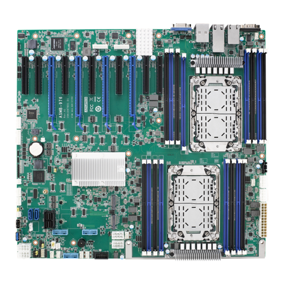
Page 13: Board Layout, Jumpers And Connectors
Board Layout, Jumpers and Connectors Connectors on the ASMB-976 are linked to external devices such as hard disk drives. In addition, ASMB-976 has a number of jumpers that are used to configure the system for specific applications. The tables below list the functions of each jumper and connector. Later sections in this chapter give instructions for setting jumpers. - Page 14 Table 1.2: Onboard LAN LED Color Definition 10/100/1000 Mbps LAN Mbps LAN Link/Activity LED Scheme LAN1 & LAN2 (1G) Left LED Right LED Link Green 10 Mbps Active Blinking green Link Amber Green 100 Mbps Active Amber Blinking green Link Green Green 1000 Mbps...
- Page 15 Table 1.4: Jumpers Label Function Default JCMOS1 CMOS Clear JME1 ME update JWDT1 Watch Dog Reset PSON1 AT(1-2) / ATX(2-3) JCASE1 Chassis case open alarm JTHR_SEL On board(1-2)/external thermistor(2-3) Keep CMOS data/ Clear CMOS data/ disable ME update/ Enable ME update/ Table 1.5: Connectors Label Function...
- Page 16 Table 1.5: Connectors EX_THR1 Connector for external thermistor GPIO1 GPIO function for customize usage HDAUD1 Audio header JFP1/JFP2/JFP3 Front panel pin header KBMS1 For additional keyboard/mouse LAN1_2, LAN3_4 RJ-45 LAN connector LANLED1 LAN LED extension connector LPC1 LPC port for debug & TPM module SSATA4, SSATA5 SATA port 4/5 for M.2 2242 SATA SSD PMBUS1...
-
Page 17: Block Diagram
Table 1.6: Onboard LED Description LED Definition Off: On (Green): 5V_LED1 Power on LED Power off System is On On (Green): Off: 5VSB_LED1 Standby LED System is ON, in sleep mode, No input AC Power or in soft-off mode BMC heartbeat LED Blinking (Green): LED3 (ASMB-976T2 SKU... -
Page 18: Memory Installation Procedures
Memory Installation Procedures Memory performance is affected by different DIMM configurations. To reach optimal memory interleaving, be sure to install identical DIMM types with the same size, speed, and number of ranks on those memory slots corresponding to the correct pro- cessor. - Page 19 Table 1.8: DIMM Configuration with Dual CPU DIM- DIMM DIM- DIM- DIMM DIMM DIM- DIMM DIM- DIM- DIM- DIM- DIM- DIMM DIM- DIM- Channel Quantity memory installed Note! 1, 3, 5, 7, 9, 11 DIMMs are not recommended DIMM population when dual CPU were installed.
-
Page 20: Processor Installation
Processor Installation The ASMB-976 is designed for Intel Xeon processor scalable family. Remove dust cover. Install CPU on CPU clip and align pin 1 mark. ASMB-976 User Manual... - Page 21 Install the CPU clip assembly on the heatsink as a processor + heatsink module. Put the processor heatsink module into the motherboard bolster plate by using a T-30 screw driver (follow heatsink label direction 1-2-3-4). ASMB-976 User Manual...
- Page 22 ASMB-976 User Manual...
-
Page 23: Chapter 2 Connections
Chapter Connections... -
Page 24: Introduction
Introduction You can access most of the connectors from the top of the board as it is being installed in the chassis. If you have a number of cards installed, you may need to par- tially remove a card to make all the connections. USB Ports and LAN Port (USB1~USB10, LAN1~LAN5) The USB ports comply with USB 2.0 &... -
Page 25: Vga Connector (Vga1)
VGA Connector (VGA1) The ASMB-976 includes a VGA interface that can drive conventional CRT and LCD displays. Serial Ports (COM1~2) The ASMB-976 offers one serial port on the rear plate and one 2.54mm pitch 9-pin header onboard. ASMB-976 User Manual... -
Page 26: Ps2 Keyboard And Mouse Connectors (Kbms1)
PS2 Keyboard and Mouse Connectors (KBMS1) The 6-pin KBMS1 connector is for additional keyboard & mouse device usage. CPU Fan Connector (CPUFAN0~1) If a fan is used, this connector supports cooling fans that draw up to 1.5A (18W). ASMB-976 User Manual... -
Page 27: System Fan Connector (Sysfan0~6)
System Fan Connector (SYSFAN0~6) Front Panel Connector (JFP1) There are several external switches and LEDs to monitor and control the ASMB-976. ASMB-976 User Manual... -
Page 28: Power Led (Jfp3)
2.8.1 Power LED (JFP3) JFP3 pin 1 and pin 3 are for the power LED. Refer to Appendix B for detailed infor- mation on the pin assignments. If an ATX power supply is used, the system’s power LED status will be as indicated as follows. Table 2.1: ATX Power Supply LED Status ACPI Power Mode LED (ATX power) -
Page 29: Case Open (Jcase1)
Case Open (JCASE1) A chassis Intrusion header is located at JCASE1 on the motherboard. Attach the appropriate cable from the chassis to be informed of a chassis intrusion when the chassis is opened. The default function is disabled and Pin 1-2 is bridged by a jumper cap. -
Page 30: Front Panel Lan Indicator Connector (Lanled1)
2.11 Front Panel LAN Indicator Connector (LANLED1) 2.12 SATA and sSATA (SATA0~7, sSATA0~1) ASMB-976 features ten serial ATA III interfaces (up to 600 MB/s) which eases cabling to hard drives with thin and long cables. ASMB-976 User Manual... -
Page 31: Connector (Ssata3 And Pcie Gen3 And Pcie Gen4)
2.13 M.2 Connector (sSATA3 and PCIe gen3 and PCIe gen4) The M.2 2280 connectors support SATA and PCIe devices. ASMB-976 User Manual... -
Page 32: Pcie Expansion Slots
2.14 PCIe Expansion Slots The ASMB-976 provides nine expansion slots that can support four double-deck cards, one PCIe x 8 card and one PCIe x4 card. Slot Length Link PCI-E Generation PCIe link provide from SLOT1 PCIE x8 PCIE x8 CPU0 SLOT2 PCIE x8... -
Page 33: Auxiliary Power Connector (Atxpwr1/Atx12V1/Atx12V/Atx12V3/ Atx12V4)
2.15 Auxiliary Power Connector (ATXPWR1/ ATX12V1/ATX12V/ATX12V3/ATX12V4) Note! Please use a power supply which is of SSI type; minimum output should be at least 700W with 5Vsb @2.5A. ATXPWR1 & ATX12V1 & ATX12V3 should be all connected with power supply, otherwise ASMB-976 will not boot up normally. 2.16 HD Audio Interface Connector (HDAUD1) ASMB-976 User Manual... -
Page 34: Lpc Connector (Lpc1)
2.17 LPC Connector (LPC1) ASMB-976 has one LPC connector that can be used to install Advantech's TPM Module (P/N: PCA-TPM-00A1E, PCA-TPM-00B1E) for security management. 2.18 CMOS Clear and ME Update Connector (JCMOS1, JME1) Setting jumper from pin 1-2 to pin 2-3, then back to pin 1-2 to reset CMOS data and enable ME update. -
Page 35: Pmbus Connector (Pmbus1)
2.19 PMBUS Connector (PMBUS1) 2.20 Front Panel SMBUS Connector (SMBUS1) ASMB-976 User Manual... -
Page 36: Bmc Ic Socket (Cn2)
ASMB-976T2 sku. 2.22 VOLT1 Connector (VOLT1) VOLT1 connects to the alarm board on the Advantech chassis. These alarm boards give warnings if a power supply or fan fails, if the chassis overheats, or if the back- plane malfunctions. -
Page 37: Gpio Connector (Gpio1)
2.23 GPIO Connector (GPIO1) 2.24 Intel Virtual RAID (VROC1) Intel VROC license key of VMD allows NVMe SSDs to connect via PCIe and directly manages the CPU for better RAID performance. Enable NVMe SSD RAID, hot-plug and LED management features via VROC connector. ASMB-976 User Manual... -
Page 38: Nvme Raid Led Control (Pehp1)
2.25 NVMe RAID LED Control (PEHP1) Connect to storage chassis to enable NVMe RAID LED control feature. ASMB-976 User Manual... -
Page 39: Ami Bios
Chapter AMI BIOS... -
Page 40: Introduction
Introduction With the AMI BIOS Setup program, you can modify BIOS settings and control the special features of your computer. The Setup program uses a number of menus for making changes and turning the special features on or off. This chapter describes the basic navigation of the ASMB-976 setup screens. -
Page 41: Bios Setup
BIOS Setup 3.2.1 Main Menu Press <Del> during bootup to enter AMI BIOS CMOS Setup Utility; the Main Menu will appear on the screen. Use arrow keys to select among the items and press <Enter> to accept or enter the sub-menu. The Main BIOS setup screen has two main frames. -
Page 42: Advanced Bios Features Setup
3.2.2 Advanced BIOS Features Setup Select the Advanced tab from the ASMB-976 setup screen to enter the Advanced BIOS setup screen. You can select any of the items in the left frame of the screen, such as CPU configuration, to go to the sub menu for that item. You can display an Advanced BIOS Setup option by highlighting it using the <Arrow>... - Page 43 3.2.2.1 Trusted Computing Security Device Support Enables or disables BIOS support for security device. Purchase Advantech LPC TPM module to use TPM function. (P/N: PCA-TPM- 00A1E/PCA-TPM-00B1E.) ASMB-976 User Manual...
- Page 44 3.2.2.2 ACPI Settings Lock Legacy Resources Enable or disable lock legacy resources feature. 3.2.2.3 IT8528 EC Super IO Configuration ASMB-976 User Manual...
- Page 45 Serial Port 1 Configuration – Serial Port Enable or disable serial port 1. – Change Settings To select an optimal setting for serial port 1. ASMB-976 User Manual...
- Page 46 Serial Port 2 Configuration – Serial Port Enable or disable serial Port 2. – Change Settings To select an optimal setting for serial port 2. ASMB-976 User Manual...
- Page 47 3.2.2.4 IT8528 HW Monitor Watchdog Timer Enable or disable the watchdog timer function. CPU ACPI Shutdown Temperature Enable or disable the ACPI shutdown temperature threshold. When the system reaches the shutdown temperature, it will be automatically shut down by ACPI OS to protect the system from overheat damage.
- Page 48 3.2.2.5 Serial Port Console Redirection ASMB-976 User Manual...
- Page 49 Console Redirection Settings – Terminal Type Select a terminal type to be used for console redirection. Options available: VT100/VT100+/ANSI/VT-UTF8. – Bits Per Second Select the baud rate for console redirection. Options available: 9600/19200/57600/115200. – Data Bits – Parity A parity bit can be sent with the data bits to detect some transmission errors. Even: parity bit is 0 if the number of 1's in the data bits is even.
- Page 50 – Recorder Mode When this mode enabled, only text will be send. This is to capture Terminal data. Options available: Enabled/Disabled. – Resolution 100x31 Enables or disables extended terminal resolution. – Putty Keypad Select function key and keypad on putty. Legacy Console Redirection Settings ...
- Page 51 3.2.2.6 PCI Subsystem Settings Above 4G Decoding Enable or disable 64-bit capability. Devices to be decoded in above 4G address space (only if the system supports 64-bit PCI decoding). Note! Some graphic or GPU cards need to enable 4G Decoding. ASMB-976 User Manual...
- Page 52 3.2.2.7 USB Configuration Legacy USB Support This is for supporting USB device under a legacy OS such as DOS. When choosing “Auto”, the system will automatically detect if any USB device is plugged into the computer and enable USB legacy mode when a USB device is plugged, or disable USB legacy mode when no USB device is attached.
- Page 53 Device Reset Time-out Selects the USB device reset time-out value. [10,20,30,40 sec] Device Power-up Delay This item appears only when Device power-up delay item is set to [manual]. ASMB-976 User Manual...
- Page 54 Mass Storage Devices Default is “Auto” to enumerate mass storage devices according to media format. ASMB-976 User Manual...
- Page 55 3.2.2.8 Network Stack Configuration Enable or disable UEFI network stack function. ASMB-976 User Manual...
- Page 56 3.2.2.9 CSM Configuration CSM Support Enables or Disables UEFI CSM (Compatibility Support Module) to support a leg- acy PC boot process. Default is Disabled. ASMB-976 User Manual...
- Page 57 GateA20 Active This item is useful when RT code is executed above 1MB. When it's set as “Upon Request”, GA20 can be disabled using BIOS services. When it's set as “Always”, it does not allow disabling of GA20. ASMB-976 User Manual...
- Page 58 Option ROM Messages To “Force BIOS or keep current” to set the display mode for Option ROM. Boot Option Filter Change UEFI/legacy ROM priority for boot option. ASMB-976 User Manual...
- Page 59 Network Control the execution of UEFI and legacy PXE OpROM. Storage Control the execution of UEFI and legacy storage OpROM. ASMB-976 User Manual...
- Page 60 Video Control the execution of UEFI and Legacy Video OpROM. Other PCI Devices Determines OpROM execution policy for devices other than Network., Storage, or Video. ASMB-976 User Manual...
- Page 61 3.2.2.10 iSCSI Configuration Host iSCSI Configuration The worldwide unique name of iSCSI Initiator. Only IQN format is accepted. Range is from 4 to 223. ASMB-976 User Manual...
-
Page 62: Platform Configuration
3.2.3 Platform Configuration ASMB-976 User Manual... - Page 63 3.2.3.1 PCH Configuration PCH Devices This item is to set up IO Controller Hub devices. Restore AC Power Loss Specify what state to go to when power is re-applied after a power failure (G3 state). ASMB-976 User Manual...
- Page 64 – VGA Priority Determines priority between onboard and 1st off-board video device found. Onboard VGA Controller Enable/Disable Onboard VGA Controller (ASPEED AST2500). Detected Display Device from Select to display from which PCIe Slot. ASMB-976 User Manual...
- Page 65 RTC Wake System from S5 Enable or disable system wake on alarm event. PCI Express Configuration ASMB-976 User Manual...
- Page 66 PCIE SLOTS PCIE SLOTS Root Port Settings. PCIe M.2 Slot M.2 PCIE SLOT Root Port Settings. ASMB-976 User Manual...
- Page 67 PCH SATA Configuration – SATA Controller Enable or disable SATA devices. – Configure SATA as Set as AHCI or RAID when SATA controllers are enabled. – Support ALPM ASMB-976 User Manual...
- Page 68 Enable or disable Aggressive Link Power Management (ALPM) protocol for Advanced Host Controller Interface-compliant (AHCI) Serial ATA (SATA) devices. – SATA Port 0~7 Enable or disable SATA port 0~7. – Hot Plug Port 0~7 Designates SATA port 0~7 as hot pluggable. –...
- Page 69 Networking – LAN1 Controller Enable or disable Intel I210 Controller support. – LAN1 PXE OpROM Enable or disable Boot option for Intel I210 controller. – LAN2 Controller Enable or disable Intel I210 Controller support. – LAN2 PXE OpROM Enable or disable Boot option for Intel I210 controller. –...
-
Page 70: Socket Configuration
3.2.3.2 Server ME Configuration This page shows the Server ME configuration information. 3.2.4 Socket Configuration ASMB-976 User Manual... - Page 71 3.2.4.1 Processor Configuration Per-Socket Configuration Use this to select how many processor cores you want to activate when you are using a dual or quad core processor. Hyper-threading [All] Enable or disable Intel Hyper Threading technology. Execute Disable Bit ...
- Page 72 DCU Streamer Prefetcher Enable prefetch of next L1 data line based upon multiple loads in same cache line. DCU IP Prefetcher Enable prefetch of next L1 line based upon sequential load history. DCU Mode Change the data cache unit mode. AES-NI ...
- Page 73 Link Speed Mode Select the QPI link speed as either the Fast mode or Slow mode. ASMB-976 User Manual...
- Page 74 Link Frequency Select Allows for selecting the QPI Link frequency. ASMB-976 User Manual...
- Page 75 Link L0p Enable Enable or disable QPI Link0p. Link L1 Enable Enable or disable QPI Link1. ASMB-976 User Manual...
- Page 76 3.2.4.3 Memory Configuration NUMA Enable or disable non uniform memory access (NUMA). Memory Technology Display memory topology with DIMM population information. ASMB-976 User Manual...
- Page 77 3.2.4.4 IIO Configuration Socket0 PCIe Configuration PCIe port bifurcation control and select target link speed as Gen1, Gen2, Gen3, Gen4. ASMB-976 User Manual...
- Page 78 ASMB-976 User Manual...
- Page 79 ASMB-976 User Manual...
- Page 80 ASMB-976 User Manual...
- Page 81 Socket1 PCIe Configuration PCIe port bifurcation control and select target link speed as Gen1, Gen2, Gen3, Gen4. ASMB-976 User Manual...
- Page 82 ASMB-976 User Manual...
- Page 83 ASMB-976 User Manual...
- Page 84 ASMB-976 User Manual...
- Page 85 Intel VT for Directed I/O (VT-d) Enable or disable Intel Virtualization Technology for Directed I/O. ASMB-976 User Manual...
- Page 86 Intel VMD Technology Enable or disable Intel Volume Management Device Technology. PCIe Hot Plug Enable or disable PCIe hot plug for Intel VROC, while using Intel VROC, please enable this item. PCI-E ASPM Support (Global) Set the ASPM level to Disable, Per-Port or L1 state only. ASMB-976 User Manual...
- Page 87 3.2.4.5 Advanced Power Management Configuration ASMB-976 User Manual...
- Page 88 CPU P State Control ASMB-976 User Manual...
- Page 89 CPU C State Control Package C State Control ASMB-976 User Manual...
-
Page 90: Server Management
3.2.5 Server Management BMC Support Enable or disable interfaces to communicate with BMC. Wait for BMC If enabled, motherboard will wait 30 ~ 60 seconds until BMC module boots up completely. After that, the normal BIOS post screen will be displayed. If disabled, motherboard will not wait for BMC module's response. - Page 91 3.2.5.1 System Event Log SEL Components Enable/Disable all features of system event logging during boot. Erase SEL Choose options for erasing SEL. When SEL is Full Choose options for reactions to a full SEL. Log EFI Status Codes ...
- Page 92 ASMB-976 User Manual...
- Page 93 3.2.5.2 BMC Self Test Log Erase Log Erase log options. When Log is Full Select the action to be taken when log is full. ASMB-976 User Manual...
- Page 94 3.2.5.3 BMC Network Configuration Configuration Address Source Select to configure LAN channel parameters statically or dynamically (by BMC). Unspecified option will not modify any BMC network parameters during BIOS phase. ASMB-976 User Manual...
- Page 95 3.2.5.4 BMC User Settings ASMB-976 User Manual...
-
Page 96: Security
3.2.6 Security ASMB-976 User Manual... - Page 97 Note! With AC power & Battery. Short CMOS1 Jumper: Date/Time & Password: Keep Setting: reset to default AC power and CMOS battery are removed. Short CMOS1 Jumper: Date/Time: reset to default Password: Keep Setting: reset to default ASMB-976 User Manual...
- Page 98 Secure Boot – Secure Boot Secure Boot feature is active if Secure Boot is Enabled. Platform Key (PK) is enrolled and the System is in User mode. The mode change requires plat- form reset. – Secure Boot Mode Secure Boot mode options. ASMB-976 User Manual...
- Page 99 – Restore Factory Keys Force System to User Mode. – Key Management Enables expert users to modify Secure Boot Policy variables without full authentication. ASMB-976 User Manual...
-
Page 100: Boot
3.2.7 Boot Setup Prompt Timeout Number of seconds to wait for setup activation key. Bootup NumLock State Select the keyboard NumLock state as “On” or “Off”. Quiet Boot Enable or disable quiet boot option. Boot Option Priorities ... -
Page 101: Save & Exit
3.2.8 Save & Exit Save Changes and Exit Exit system setup after saving the changes. Discard Changes and Exit Exit system setup without saving any changes. Save Changes and Reset Reset the system after saving changes. Discard Changes and Reset ... - Page 102 ASMB-976 User Manual...
-
Page 103: Chipset Software Installation Utility
Chapter Chipset Software Installation Utility... -
Page 104: Before Beginning
To facilitate the installation of the enhanced display drivers and utility software, read the instructions in this chapter carefully. The drivers for the ASMB-976 are available online for download from the Advantech support website. Before beginning, it is important to note that most display drivers need to have the relevant software application already installed on the system prior to installing the enhanced display drivers. -
Page 105: Graphic Setup
Chapter Graphic Setup... -
Page 106: Introduction
OS that you need. Note! If ASMB-976 Series carries an additional graphics card for VGA output, please set this additional graphic card as "major output" under the "Display properties" of OS. -
Page 107: Lan Configuration & Usb
Chapter LAN Configuration & USB 3.0... -
Page 108: Lan Configuration
LAN Configuration 6.1.1 Introduction The ASMB-976T2 Series has two Gigabit Ethernet LAN connections via dedicated PCI Express x1 lanes: GbE LAN1 - Intel I210; GbE LAN2 - I210; two 10G Base-T LAN connectors LAN3 and LAN4 - Intel X550 PHY. They eliminate bottlenecks of net- work data flow and incorporate Gigabit Ethernet at 10 Gbps. -
Page 109: Usb 3.2 Gen1
USB 3.2 gen1 6.2.1 Introduction ASMB-976 offers nine USB 3.2 gen1 ports, two in rear side and seven via onboard header. The USB 3.2 gen1 could provide the bandwidth up to 500MB/s to shorter the time for data transmission. 6.2.2 Windows Series Driver Setup Select folder “04_USB”... - Page 110 ASMB-976 User Manual...
-
Page 111: Programming The Watchdog Timer103
Appendix Programming the Watchdog Timer... -
Page 112: Watchdog Timer Overview
Watchdog Timer Overview The ASMB-925 Series watchdog timer can be used to monitor system software oper- ation and take corrective action if the software fails to function within the programmed period. This section describes the operation of the watchdog timer and how to pro- gram it.The watchdog timer is built in to the EC controller IT8528E. - Page 113 Wait IBF clear 0x29A, BIT1, = 0 Write 0x04 to 0x299 port (Warm) Reset event Wait IBF clear 0x29A, BIT1, = 0 Write 0x28 to 0x29A Start watchdog Wait 1 ~ 9 Wait IBF clear 0x29A, BIT1, = 0 Write 0x29 to 0x29A Stop watchdog Wait IBF clear 0x29A, BIT1, = 0...
- Page 114 ASMB-976 User Manual...
-
Page 115: Appendix B I/O Pin Assignments
Appendix I/O Pin Assignments... -
Page 116: Usb3.2 Gen1 Header(Usb3_34, Usb3_56, Usb3_78)
USB3.2 gen1 Header(USB3_34, USB3_56, USB3_78) Table B.1: USB Header Signal Signal +5 V STDA_SSRX- STDA_SSRX+ STDA_SSRX- STDA_SSRX+ N/C (OC pin reserved) STDA_SSRX+ STDA_SSRX- STDA_SSRX+ STDA_SSRX- +5 V VGA Connector (VGA1) Table B.2: VGA Connector Signal Signal GREEN BLUE H-SYNC V-SYNC ASMB-976 User Manual... -
Page 117: Interface (Com2)
RS-232 Interface (COM2) Table B.3: RS-232 Interface Signal External Keyboard Connector (KBMS1) KBMS1 Table B.4: External Keyboard Connector Signal KB CLK KB DATA MS DATA MS CLK ASMB-976 User Manual... -
Page 118: Cpu And System Fan Power Connector
CPU and System Fan Power Connector (CPUFAN0~1, SYSFAN0~SYSFAN6) Table B.5: Fan Power Connector Signal +12 V TACH Power LED (JFP3) Table B.6: Power LED Function LED power (3.3 V) Ground External Speaker Connector (JFP2) 1 4 7 10 Table B.7: External Speaker Connector Function SPK+ SPK-... - Page 119 Reset Connector (JFP1) 9 12 Table B.8: Reset Connector Signal RESET HDD LED Connector (JFP1) Table B.9: HDD LED Connector Signal HDD_LED+ HDD_LED- B.10 ATX Soft Power Switch (JFP1) Table B.10: ATX Soft Power Switch Signal PWR-BTN ASMB-976 User Manual...
- Page 120 B.11 Front Panel SMBus Connector (SMBUS1) Table B.11: Front Panel SMBus Connector (SMBUS1) Signal SMB_CLK_RESUME SMB_DATA_RESUME B.12 USB/LAN Ports (IPMI_LAN5_USB3_12) Table B.12: USB Port Signal Signal VCC_DUAL Data0+ Data0- Table B.13: Giga LAN 10/100/1000 Base-T RJ-45 Port Signal Signal MID0+ MID2+ MID0- MID2-...
- Page 121 B.13 Audio Connector (HDAUD1) Table B.14: Front Panel Audio Connector Signal Signal +5V_AUDIO ACZ_SYNC ACZ_BITCLK ACZ_SDOUT ACZ_SDIN0 ACZ_SDIN1 ACZ_RST +12V_AUDIO B.14 Alarm Board Connector (VOLT1) Table B.15: Alarm Board Connector Signal Signal 5VSB +3.3V -12V +12V B.15 Case Open Connector (JCASE1) Table B.16: Case Open Connector Signal CASEOP...
- Page 122 B.16 Front Panel LAN LED Connector (LANLED1) Table B.17: LAN LED Connector Signal Signal LAN1_LED_ACT# LAN2_LED_ACT# +V3.3_AUX +V3.3_AUX LAN3_LED_ACT# LAN4_LED_ACT# +V3.3_AUX +V3.3_AUX B.17 SATA SGPIO (SGPIO1/SGPIO2) Table B.18: SATA SGPIO Connector Signal SGPIO_SATA_CLOCK SGPIO_SATA_LOAD SGPIO_SATA_DATA0 SGPIO_SATA_DATA1 ASMB-976 User Manual...
- Page 123 B.18 LPC Connector (LPC1) Table B.19: LPC Connector (LPC1) Signal Signal CLK_24M_LPCCN LPC_AD1 PLTRST_LPC LPC_AD0 LPC_FRAME# +3.3 V LPC_AD3 LPC_AD2 SMB_SCL_LPC SERIRQ_PCH SMB_SDA_LPC +5V_AUX B.19 Clear CMOS and Update ME Connector (JCMOS1, JME1) Table B.20: Clear CMOS and Update ME Connector (JCMOS1, JME1) Signal Signal JCMOS1...
- Page 124 B.20 PMBUS Connector (PMBUS1) Table B.21: PMBUS Connector (PMBUS1) Signal SMB_SCL_PM SMB_SDA_PM SMB_ALERT_PM# +V3.3_AUX B.21 GPIO Connector (GPIO1) Table B.22: GPIO Connector (GPIO1) Signal Signal EC_GPIO0 EC_GPIO4 EC_GPIO1 EC_GPIO5 EC_GPIO2 EC_GPIO6 EC_GPIO3 EC_GPIO7 +VCC_GPIO ASMB-976 User Manual...
- Page 125 ASMB-976 User Manual...
- Page 126 No part of this publication may be reproduced in any form or by any means, such as electronically, by photocopying, recording, or otherwise, without prior written permission from the publisher. All brand and product names are trademarks or registered trademarks of their respective companies. © Advantech Co., Ltd. 2022...
Need help?
Do you have a question about the ASMB-976 Series and is the answer not in the manual?
Questions and answers