Summit ALBV15 User Manual
Beverage merchandisers
Hide thumbs
Also See for ALBV15:
- Instruction manual (17 pages) ,
- User manual (32 pages) ,
- User manual (32 pages)
Table of Contents
Advertisement
BEVERAGE MERCHANDISERS
ALBV15
AL57G
SCR1400W
SCR1400WLH
SCR1401
SCR1401LH
SDBV2445
SDG1526
LABV2430
ADBV2441
BEFORE USE, PLEASE READ AND FOLLOW ALL SAFETY RULES AND OPERATING INSTRUCTIONS.
Write Serial Nos. (on lower left corner of
inside cabinet) here:
Models:
SCR1536BG
SCR2464
SCR610BL
SCR611GLOS
ASDG1521
LABV15442
LBV1546
SDBV1555
SDG2415
LBV2434
User Manual
An ISO 9001:2015 registered company
SCR610BLSD
SCR1156
ADBV1551
ASDG2411
Felix Storch, Inc.
770 Garrison Ave
Bronx, New York 10474
www.summitappliance.com
Advertisement
Table of Contents

Related Manuals for Summit ALBV15


Summary of Contents for Summit ALBV15
- Page 1 BEVERAGE MERCHANDISERS Models: ALBV15 AL57G SCR1536BG SCR2464 SCR610BLSD SCR1400W SCR1400WLH SCR610BL SCR611GLOS SCR1156 SCR1401 SCR1401LH ASDG1521 LABV15442 ADBV1551 SDBV2445 SDG1526 LBV1546 SDBV1555 ASDG2411 LABV2430 ADBV2441 SDG2415 LBV2434 User Manual BEFORE USE, PLEASE READ AND FOLLOW ALL SAFETY RULES AND OPERATING INSTRUCTIONS.
-
Page 2: Table Of Contents
TABLE OF CONTENTS Appliance Safety Important Safeguards Location of Parts Installation Instructions 10-15 Before Using your Appliance Installation of your Appliance 10-11 Electrical Connection Reversing the Door Swing of your Appliance 12-14 Adjusting the Kick Plate Installing the Stainless Steel Handle 14-15 Operating your Appliance 15-20... -
Page 3: Appliance Safety
APPLIANCE SAFETY Your safety and the safety of others are very important. We have provided many important safety messages in this manual and on your appliance. Always read and obey all safety messages. This is the Safety Alert Symbol. The symbol alerts you to potential hazards that can kill or injure you and others. - Page 4 - The more coolant there is in an appliance, the larger the room it should be installed in. In the event of a leakage, if the appliance is in a small room, there is the danger of combustible gases building up. For every ounce of coolant at least 325 cubic feet of room, space is required.
-
Page 5: Location Of Parts
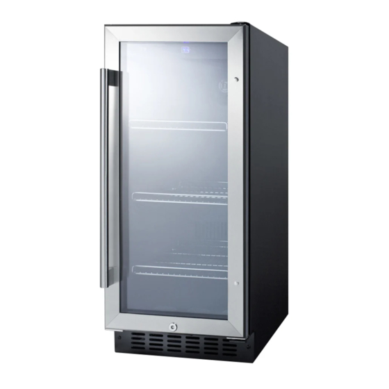
LOCATION OF PARTS Models ALBV15 / SCR1536BG Digital Control Panel Door Shelves (3) Handle Security Lock Kick-Plate Adjustable Legs Cabinet Model SCR2464 Digital Control Panel Door Shelves (3) Handle Security Lock Kick-Plate Adjustable Legs Cabinet... - Page 6 Model AL57G Models SCR1400W / SCR1400WLH* Digital Control Panel Door Shelves (6) Handle Security Lock Kick-Plate Adjustable Legs Cabinet * NOTE: Model SCR1400WLH opens from the right, so the handle is on that side.
- Page 7 Model SCR611GLOS Digital Control Panel Door Shelves (3) Handle Security Lock Kick-Plate Adjustable Legs Model SCR610BL / SCR610BLSD* Door Shelves (3) Handle Security Lock Kick-Plate Adjustable Legs Digital control panel Cabinet * NOTE: Model SCR610BLSD has a solid door.
- Page 8 Model SCR1156 Door Shelves (4) Handle Security Lock Kick-Plate Adjustable Digital control panel Legs Cabinet Models SCR1401 / SCR1401LH* Digital Control Panel Door Shelves (6) Handle Security Lock Kick-Plate Adjustable Legs Cabinet...
- Page 9 * NOTE: Model SCR1401LH opens from the right, so the handle is on that side. Models ASDG1521 / LABV15442 / ADBV1551 / SDG1526 / LBV1546 / SDBV1555 Handle Digital Control Panel Door Shelves (3) LED Light Kick-Plate Adjustable Security Legs Lock Cabinet Models ASDG2411 / LABV2430 / ADBV2441 / SDG2415 / LBV2434 / SDBV2445...
-
Page 10: Installation Instructions
INSTALLATION INSTRUCTIONS Before Using your Appliance • Remove the exterior and interior packing. CAUTION: After unpacking you MUST allow this appliance to stand upright for at least 2 hours to allow the lubricant and refrigerant to drain back into the compressor and stabilize. Failure to do so may adversely affect performance and the lifetime of this unit. - Page 11 Model No. (Inch/mm) (Inch/mm) (Inch/mm) (Inch/mm) (Inch/mm) (Inch/mm) 23⅝" / 600 ALBV15 23½" / 595 14¾" / 375 15" / 380 31½" / 800 31⅝" / 803 34⅛" / 866 SCR1536BG 34" / 864 22¾"...
-
Page 12: Electrical Connection
Electrical Connection This appliance should be properly grounded for your safety. The power cord of this appliance is equipped with a three-prong plug that fits with standard three-prong wall outlets to minimize the possibility of electrical shock. Do not under any circumstances cut or remove the third (grounding) prong from the power cord supplied. - Page 13 Models ALBV15 / SCR1536BG / SCR2464 / SCR610BL / SCR610BLSD / SCR611GLOS 1. Remove the bottom hinge (2) by unscrewing the four lock screws (1). Hold the door firmly after removing the screws. (Fig. 1) 2. Gently pull down to remove the...
-
Page 14: Adjusting The Kick Plate
Adjusting the Kick Plate Only for Models ALBV15 / AL57G / ASDG1521 / LABV15442 / ADBV1551 / SDG1526 / LBV1546 / SDBV1555 / ASDG2411 / LABV2430 / ADBV2441 / SDG2415 / LBV2434 / SDBV2445. The pre-fitted kick-plate of the appliance includes an adjustable kick-plate section that is initially seated behind the upper section. -
Page 15: Operating Your Appliance
For the SCR610BLSD model: 1. Use a screwdriver to remove the screws on the side of the door where the handle is to be installed. 2. Align the handle (2) with the screws (1) removed as above. 3. Tighten the screws using a Phillips head screwdriver until the handle is both flush and secured tightly against the door side (3). -
Page 16: Settings Mode
Light Indicator / Multi-key Function The interior light indicator is the dot at the bottom right of the display. The interior light indicator will light up in showcase mode. The interior light indicator will flash when the multi-key function is selected. To perform the multi-key function, lightly touch and hold the first key, then touch the rest key for at least 5 seconds, and then release all the keys. -
Page 17: Interior Light
Fan Mode Lightly touch and hold the UP key for 5 seconds and then touch the POWER key three times. ▪ UP and DOWN keys to select the fan mode. The factory default setting is F0 or F2. ▪ F0: Silent mode - Energy saving mode F1: Dynamic Cooling mode - half time F2: Dynamic Cooling mode - full time Touch the POWER key to confirm your selection. -
Page 18: Dynamic Cooling Mode
NOTE: Pressing the POWER key once can switch off the audible alarm when the alarm is on. Used to increase (warm) the set temperature by 1°C/1ºF. To switch on the Silent mode, press and hold the UP key for 5 seconds. Three beeps will confirm the selection. -
Page 19: Sabbath Mode
You can tell whether your unit is in Dynamic Cooling or Silent mode by the sound of the internal fan motor. When the compressor is OFF if the internal fan motor is working, the unit is in Dynamic Cooling mode, but if the internal fan motor is also OFF, the unit is working in Silent mode. Sabbath Mode •... -
Page 20: Defrosting
Defrosting • The unit defrosts automatically in normal operating conditions. • The evaporator behind the rear wall of the unit defrosts automatically. The condensate collects in the drainage channel behind the rear wall of the unit and flows through the drainage hole into the drip tray near the compressor where it evaporates. -
Page 21: Troubleshooting
TROUBLESHOOTING You can solve many common problems easily, saving you the cost of a service call. Try the suggestions below to see if you can solve the problem before calling the servicer. PROBLEM POSSIBLE CAUSE REMEDY Appliance is not connected to a power Connect the appliance. - Page 22 “E7”. “E3” or “E4” indicates that the defrost sensor in the evaporator has failed. “E5” indicates a defrost heater failure. “E6” indicates a solenoid valve failure. “E7” indicates a door switch failure. Has the appliance door been open for If yes, close the door. longer than 60 seconds? If not, then the temperature has risen higher or fallen lower than the set temperature.
- Page 23 NOTES...
-
Page 24: Limited Warranty
LIMITED WARRANTY ONE-YEAR LIMITED WARRANTY Within the 48 contiguous United States, for one year from the date of purchase, when this appliance is operated and maintained according to instructions attached to or furnished with the product, the warrantor will pay for factory specified parts and repair labor to correct defects in materials or workmanship.
Need help?
Do you have a question about the ALBV15 and is the answer not in the manual?
Questions and answers