Summit ASDG1521 User Manual

Summit ASDG1521 User Manual

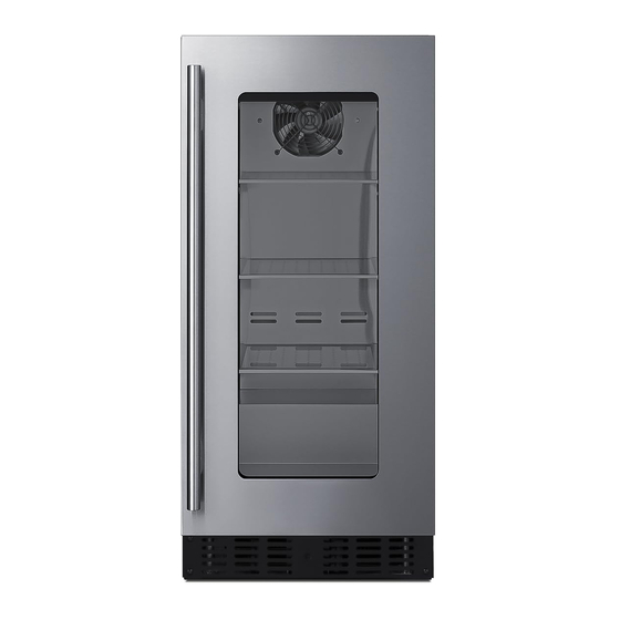
Wine and beverage cooler
Hide thumbs Also See for ASDG1521:

Advertisement

Quick Links

WINE and BEVERAGE COOLER
Beverage Coolers:
ASDG1521
DBGR1563ASD
CL181WBV
DBGR1834
Wine Coolers:
ASDW1522
DBWC1542ASD
CL18WC
DBWC1846
Wine/Beverage Coolers:
ALFD24WBV
DBFD2495ADA
BEFORE USE, PLEASE READ AND FOLLOW ALL SAFETY RULES AND OPERATING INSTRUCTIONS.
Write Serial Nos. (on lower left corner of
inside cabinet) here:
ASDG2411
DBGR2464ASD
CL24BV1
DBGR2435
ASDW2412
DBWC2443ASD
CL244WC2
DBWC2447
CLFD243WBV
DBFD2496
User Manual
MODELS:
SDHG1533
DBGR1565SD
ALBV15
DBGR1562ASD
DBGR2461ADA
SDHW1532
DBWC1544SD
ALWC15
DBWC1541ADA
An ISO 9001:2015 registered company
Bronx, New York 10474
www.summitappliance.com
SDHG2443
CL156BV
DBGR2466SD
DBGR1569
AL57GPNR
SDHW2442
CL155WC1
DBWC2445SD
DBWC1549
Felix Storch, Inc.
770 Garrison Ave

Advertisement

Table of Contents
loading
Need help?

Need help?

Do you have a question about the ASDG1521 and is the answer not in the manual?

Questions and answers

Subscribe to Our Youtube Channel

Summary of Contents for Summit ASDG1521

  • Page 1 WINE and BEVERAGE COOLER MODELS: Beverage Coolers: ASDG1521 ASDG2411 SDHG1533 SDHG2443 CL156BV DBGR1563ASD DBGR2464ASD DBGR1565SD DBGR2466SD DBGR1569 CL181WBV ALBV15 AL57GPNR CL24BV1 DBGR1834 DBGR1562ASD DBGR2461ADA DBGR2435 Wine Coolers: ASDW1522 ASDW2412 SDHW1532 SDHW2442 CL155WC1 DBWC1542ASD DBWC2443ASD DBWC1544SD DBWC2445SD DBWC1549 CL18WC CL244WC2 ALWC15...
  • Page 2: Table Of Contents

    TABLE OF CONTENTS Appliance Safety Important Safeguards Disposal Location of Parts Installation Instructions 9-14 Before Using your Appliance Installation of your Appliance 9-11 Electrical Connection 11-12 Reversing the Door Swing of your Appliance Adjusting the Kick Plate Installing the Stainless Steel Handle Full Overlay Panel Installation Instructions 14-16 Operating your Appliance...
  • Page 3: Appliance Safety

    APPLIANCE SAFETY Your safety and the safety of others are very important. We have provided many important safety messages in this manual and on your appliance. Always read and obey all safety messages. This is the Safety Alert Symbol. The symbol alerts you to potential hazards that can kill or injure you and others.
  • Page 4 • In the event of any damage: - Avoid open flames and anything which creates a spark, - Disconnect from the power supply, - Air the room in which the appliance is located for several minutes and - Contact the Service Department for advice. •...
  • Page 5: Disposal

    • Do not use solvent-based cleaning agents or abrasives on the interior. These cleaners may damage or discolor the interior. • Use this appliance only for its intended purpose as described in this Instruction Manual. • Keep fingers out of the “pinch point” areas. Clearances between the door and cabinet are necessarily small.
  • Page 6 Wine Cooler ALWC15 / CL155WC1 / CL18WC / DBWC1541ADA Digital Control Panel Handle LED Light Door Shelves (5) Security Lock Ventilation Adjustable Grille Legs Beverage Cooler ALBV15 / AL57GPNR / CL156BV / CL181WBV / CL24BV1 / DB1562ASD / DBGR2461ADA Digital Control Panel Handle Door...
  • Page 7 Door Digital Control Panel Grille Security Adjustable Lock Legs Beverage Cooler ASDG1521 / SDHG1533 / ASDG2411 / SDHG2443 / DBGR1563ASD / DBGR1565SD / DBGR2464ASD / DBGR2466SD / DBGR1569 / DBGR1834 / DBGR2435 Shelves (3) Handle LED Light Door Digital Control...
  • Page 8: Installation Instructions

    Shelves (5) Door Digital Control Handle Panel Security Kick-plate Lock Adjustable Legs Wine/Beverage Cooler ALFD24WBV / CLFD243WBV / DBFD2495ADA / DBFD2496 LED Light Shelves (6) Shelves (2) Handle Digital Control Panel Door Ventilation Grille Adjustable Security Legs Lock INSTALLATION INSTRUCTIONS...
  • Page 9: Before Using Your Appliance

    Before Using your Appliance • Remove the exterior and interior packing. CAUTION: After unpacking you MUST allow this appliance to stand upright for at least 2 hours to allow the lubricant and refrigerant to drain back into the compressor and stabilize. Failure to do so may adversely affect performance and the lifetime of this unit.
  • Page 10 2. Models CL18WC, DBWC1846 and DBGR1834 have the same size as CL181WBV. 3. Models ALFD24WBV, DBGR2461ADA and DBFD2495ADA have the same size as AL57GPNR. 4. Models ASDG1521, DBGR1563ASD and DBWC1542ASD have the same size as ASDW1522. 5. Models SDHG1533, DBGR1565SD and DBWC1544SD have the same size as SDHW1532.
  • Page 11: Electrical Connection

    NOTE: If the unit is relocated, the bracket must be removed and installed in the new location. Securing the Appliance (If available) Pop out the cover cap on the opposite side of hinge and secure the appliance in the niche by tightening the screws through the attachment bracket if the unit is provided with an attachment bracket.
  • Page 12: Reversing The Door Swing Of Your Appliance

    The appliance should always be plugged into its own individual electrical outlet which has a voltage rating that matches the rating label on the appliance. This provides the best performance and also prevents overloading house wiring circuits that could cause a fire hazard from overheating. Never unplug the appliance by pulling on the power cord.
  • Page 13: Adjusting The Kick Plate

    Adjusting the Kick Plate (Only for ADA models) The pre-fitted kick-plate of the appliance includes an adjustable kick-plate section that is initially seated behind the upper section. In order to adjust the kick- plate height, follow the instructions below: 1. Remove the screws (1) from both the top left- and top right-hand sides of the kick-plate.
  • Page 14: Full Overlay Panel Installation Instructions

    Full Overlay Panel Installation Instructions These models are designed for field-installed overlay panel. The overlay panel covers the stainless steel to give a built-in appearance. The overlay panel and appropriate hardware are not included with the unit and the end user needs to prepare them themselves. Please follow the instructions below for installation: Door Panel Preparation Prepare the overlay panel to the dimensions shown below.
  • Page 15 If you do not want the 3mm gap, you will have the option to route the wood according to the bracket’s dimensions. Then proceed to install the bracket following the instructions below. Installing the handle on the overlay panel If reusing the handle that came with the unit: 1.
  • Page 16: Operating Your Appliance

    the door. This is done by removing the screws that attach the lock bracket and magnetic activators to the door. 6. We recommend you leave the factory-installed protective film to protect the door and prevent scratching while installing the panel. 7.
  • Page 17 Used to decrease (cool) the set temperature by 1°C/1ºF. Light Indicator / Multi-key Function The interior light indicator is the dot at the bottom right of the display. The interior light indicator will light up in showcase mode. The interior light indicator will flash when the multi-key function is selected. To perform the multi- key function, lightly touch and hold the first key, then touch the rest key for at least 5 seconds and then release all the keys.
  • Page 18 Used to increase (warm) the set temperature by 1°C/1ºF. DOWN Used to decrease (cool) the set temperature by 1°C/1ºF. Indicator Light The indicator light is the dot at the bottom right of the display. The indicator light will be on when a multi- key function is selected.
  • Page 19 Control Panel with LCD Display ON/OFF Power To turn the appliance off, lightly touch and hold the key for 5 seconds until temperature display goes out. To turn the appliance on, lightly touch and hold the key for 1 second until temperature display lights up.
  • Page 20 If in 2 minutes or longer without touching any key, the child lock will be activated automatically for models with the control outside of cabinet. To cancel the lock, lightly touch the UP and DOWN keys simultaneously for at least 5 seconds until the symbol is go out.
  • Page 21 To decrease (cool) the set temperature by 1°C or 1ºF. Setting Selector Select the temperature and humidity you want to set. Symbols in the Display Temperature or Error code display for upper/left zone Temperature or Error code display for lower/right zone Compressor is ON.
  • Page 22: Settings Mode

    • The set temperature will temporarily flash in the display for 5 seconds after the temperature has been set. Then the display shows the current inner temperature again. • To view the set temperature at any time, touch the Setting Selector key, the set temperature will temporarily flash in the display for 5 seconds.
  • Page 23: Interior Light

    Audible Tones 1. Lightly touch and hold the UP key for 5 seconds to enter Settings mode and then touch the POWER key four (4) times. 2. Use the UP and DOWN keys to select the audible tones. • S0: sensor tone ON, alarm tone OFF •...
  • Page 24: Dynamic Cooling And Silent Mode

    • The cause of the temperature being too high may be: Warm items were placed inside Too much warm ambient air flowed in when rearranging and removing contents Power failure for some time The appliance is faulty. • The audible alarm is automatically silenced, and the temperature display stops flashing when the temperature is sufficiently cold again.
  • Page 25 • Any of the shelves can be removed to store larger items. • When removing the shelf from the rail compartment, make sure to remove all items first. Then move the shelf to the position where the notch of the shelf is exactly under the plastic post and lift the shelf.
  • Page 26: Defrosting

    Defrosting • The unit defrosts automatically in normal operating conditions. • The evaporator behind the rear wall of the unit defrosts automatically. The condensate collects in the drainage channel behind the rear wall of the unit and flows through the drainage hole into the drip tray near the compressor where it evaporates.
  • Page 27: Care And Maintenance

    CARE AND MAINTENANCE Cleaning your Appliance CAUTION: Failure to unplug the appliance during cleaning could result in electrical shock or other personal injury. • Turn off the power, unplug the appliance, and remove all items, including shelves. • Wash the inside surfaces with a solution of warm water and baking soda (about 2 tablespoons of baking soda to a quart of water).
  • Page 28: Troubleshooting

    • Ensure that the unit is adequately ventilated. Never cover air vents. • Do not keep the door open any longer than necessary. TROUBLESHOOTING You can solve many common problems easily, saving you the cost of a possible service call. Try the suggestions below to see if you can solve the problem before calling the servicer.
  • Page 29 The appliance is not properly leveled. Level the appliance with the adjustable feet. The appliance is not properly leveled. Level the appliance with the adjustable feet. The door will The door was reversed and not properly Check the door hinge and reassemble not close re-installed.
  • Page 30 However, we are required by California Law to provide the following disclosure statement in every product sold in California. "This equipment is prohibited from use in California with any refrigerants on the 'List of Prohibited Substances' for that specific end-use, in accordance with California Code of Regulations, title 17, section 95374.
  • Page 31 NOTES...
  • Page 32: Limited Warranty

    LIMITED WARRANTY ONE-YEAR LIMITED WARRANTY Within the 48 contiguous United States, for one year from the date of purchase, when this appliance is operated and maintained according to instructions attached to or furnished with the product, warrantor will pay for factory-specified parts and repair labor to correct defects in materials or workmanship. Service must be provided by a designated service company.

Table of Contents