Advertisement
Quick Links
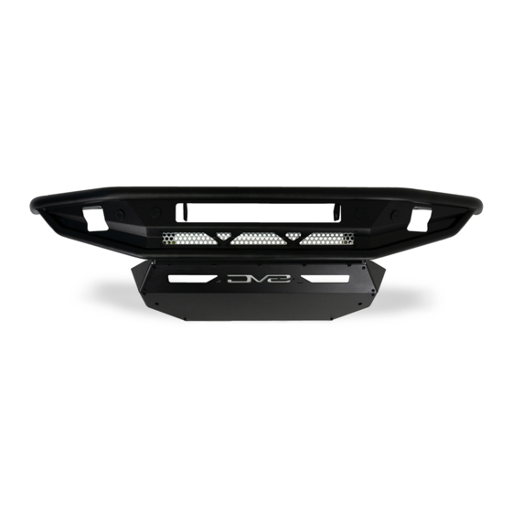
NON WINCH FRONT BUMPER COMP SERIES
2021+ BRONCO
FBBR-04
TOOLS
REQUIRED
- Snips or Scissors
- Ratchet
- 13mm, 15mm, 16mm Socket
- 13mm Wrench
- #5 Allen Head
WARNINGS/CAUTIONS BEFORE STARTING INSTALLATION
Before you install this kit —
instructions, warnings, cautions, and notes contained in
this installation instruction guide. Consult your vehicle
owner's manual for proper disconnection of electrical and
lifting of vehicle if required for installation of this product.
This install may require some technical skills and
knowledge of basic mechanical work. If you do not feel that
you are capable of performing this install please take this
product to a trained professional.
After reading this guide please contact us with any
questions or concerns before installing product.
Customer Service: 855-680-9595
DV8 Offroad is not responsible for any bodily injury or harm to you
or your vehicle as a result of an improper install.
6400 SYCAMORE CANYON BLVD.
RIVERSIDE, CALIFORNIA 92507
855-680-9595
WWW.DV8OFFROAD.COM
SKILL
LEVEL
- Novice/Intermediate
- 1 (you) to 2 persons
Little skill level required, you can
easily install it by yourself however,
additional help will be useful
Read and understand all
PRODUCT
INSTALLATION
TIME
- 3 Hours
Time to install this should only
take about 3 hours
Proper installation of this kit required knowledge of the factory
recommended procedures for removal and installation of original
equipment components. We recommend that the factory shop manual
and any special tools needed to service your vehicle be on hand during
the installation. Installation of this kit without proper knowledge of the
factory recommended procedures may affect the performance of these
components and the safety of the vehicle
• Always wear eye protection when operating power tools
Inspect all contents of this package to make sure product is not damaged
and all installation hardware has been included. If parts are missing from
kit, please be prepared to provide the following information
1. Name of purchase location
2. Bar Code on side of box
3. Date above bar code
4. Date inside box cover
MANUAL
REQUIRED
855-680-9595
NEED HELP?
Advertisement

Related Manuals for DV8 FBBR-04


Summary of Contents for DV8 FBBR-04
- Page 1 1. Name of purchase location Customer Service: 855-680-9595 2. Bar Code on side of box DV8 Offroad is not responsible for any bodily injury or harm to you 3. Date above bar code or your vehicle as a result of an improper install.
- Page 2 INSTALLATION MANUAL STEP REMOVAL OF FACTORY STEEL BUMPER Begin by removing the front plastic d-ring guards. Using a screwdriver or push pin remover, remove the (2) pins on the bottom and (2) near the top of the d-ring mount. Pull the top half away from the Bronco and set to the side.
- Page 3 INSTALLATION MANUAL STEP Once all bolts are loose, remove the plug for the fog lights and front sensors if equipped. This is located at the back end of the grill on the driver side. STEP Once unplugged, remove all (6) bumper bolts and d-rings mounts.
- Page 4 INSTALLATION MANUAL STEP Remove the rubber/plastic shroud under the grill by pulling the tabs on the shroud away (up/down) from vehicle while pulling the shroud from the vehicle. STEP If you do not have adaptive cruise control, remove the plastic cover by pushing the clip on the top down while pulling away from Bronco, and set off to the side.
- Page 5 INSTALLATION MANUAL STEP If equipped with sensors, remove the main bumper brackets from the backside of the bumper using a 13mm socket, remove the (4) hex head bolts. STEP Next, using a T40 torx bit, remove the (6) bolts securing the mount in place. Once removed, gently separate mount from bumper, and set off to the side.
- Page 6 INSTALLATION MANUAL STEP To remove the wire harness, using a flat head screwdriver or pin puller, remove all the retaining clips securing the harness to the bumper. STEP To remove the sensors, spread the two tabs on the sensor bezel and gently pull up on the sensor.
- Page 7 (5) M8x40 (4) M6 Nuts (4) M8x25 (4) M6x14 STEP Install the provided clips on the DV8 bumper. STEP On the pod lights, line the bracket up with the existing holes on both sides of the light. Drop a M6 nut in so that the light assembly holds the nut in place.
- Page 8 INSTALLATION MANUAL STEP Rotate the light so gravity holds the nut in place, and thread a M6x14 bolt in from the bottom gently until it catches the threads. Repeat on the other side of the light. Rotate bracket to the side of the light without wiring, then loosely secure hardware.
- Page 9 INSTALLATION MANUAL STEP Zip tie the wires to the zip tie tabs and snip any excess. Repeat steps 5 and 6 for other side of the bumper. Repeat steps 4,5, and 6 other side of the bumper. STEP Loosely install the light bar brackets to the bumper using a 13mm wrench and provided M8x25 hardware.
- Page 10 INSTALLATION MANUAL STEP Secure the light bar to the mounting brackets using #5 allen head and provided M8x14 hardware. Center the light and finish securing the brackets using a 13mm wrench and a #5 allen head. STEP Zip tie the wiring to the zip tie tabs and snip off any excess.
- Page 11 INSTALLATION MANUAL STEP Feed the bumper wiring harness through the bumper. Ensure the connector for the wiring will terminate on the drivers side. 855-680-9595 NEED HELP?
- Page 12 INSTALLATION MANUAL STEP Install sensor bezels and sensors in the manner indicated on the bezels and in the orientation that it was mounted on the factory bumper. Be careful during install as they are keyed for installation. STEP Zip tie the bumper wiring harness to the zip tie tabs and snip any excess.
- Page 13 INSTALLATION MANUAL STEP Ensure the wiring connectors of the lights are accessible from the bottom of the bumper. Install the bumper on the vehicle using a 16mm socket and provided M10 hardware. Torque to 45 ft-lb. NOTE: An extra pair of hands will make this process easier.
- Page 14 INSTALLATION MANUAL STEP Install the skid plate with the spacer plates using the provided M6x40 hardware and factory hardware. Use a #5 allen head and a 15mm socket. NOTE: An extra pair of hands will make this process easier. STEP Double check fitment and all hardware is secure.
Need help?
Do you have a question about the FBBR-04 and is the answer not in the manual?
Questions and answers