Advertisement
Quick Links
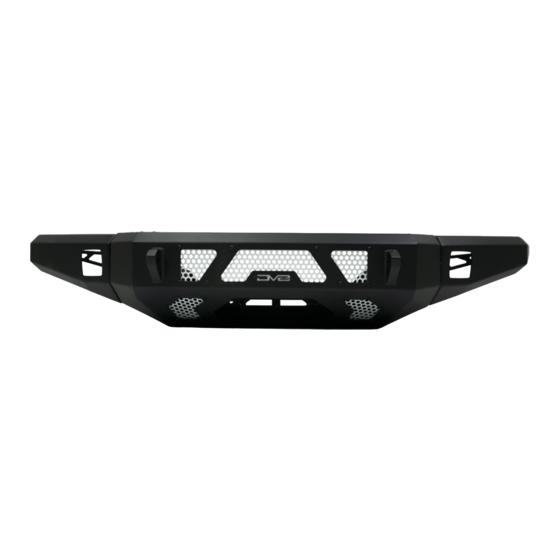
FBGX-02
2003-2009 + Lexus GX470
Front Bumper
TOOLS
REQUIRED
- 10,13,14,21,22mm
- Push Pin Removal Tool
- Grinder or Similar Cutting Tool
- #5 Allen head
WARNINGS/CAUTIONS BEFORE STARTING INSTALLATION
Before you install this kit —
instructions, warnings, cautions, and notes contained in
this installation instruction guide. Consult your vehicle
owner's manual for proper disconnection of electrical and
lifting of vehicle if required for installation of this product.
This install may require some technical skills and
knowledge of basic mechanical work. If you do not feel that
you are capable of performing this install please take this
product to a trained professional.
After reading this guide please contact us with any
questions or concerns before installing product.
Customer Service: 855-680-9595
DV8 Offroad is not responsible for any bodily injury or harm to you
or your vehicle as a result of an improper install.
6400 SYCAMORE CANYON BLVD.
RIVERSIDE, CALIFORNIA 92507
855-680-9595
WWW.DV8OFFROAD.COM
SKILL
LEVEL
- 3.5 out of 5
- 2 persons
Moderate Skill Required.
Read and understand all
PRODUCT
INSTALLATION
TIME
- 3 Hours
Time to install this should only
take approximately 3 Hours
Proper installation of this kit required knowledge of the factory
recommended procedures for removal and installation of original
equipment components. We recommend that the factory shop manual
and any special tools needed to service your vehicle be on hand during
the installation. Installation of this kit without proper knowledge of the
factory recommended procedures may affect the performance of these
components and the safety of the vehicle
• Always wear eye protection when operating power tools
Inspect all contents of this package to make sure product is not damaged
and all installation hardware has been included. If parts are missing from
kit, please be prepared to provide the following information
1. Name of purchase location
2. Bar Code on side of box
3. Date above bar code
4. Date inside box cover
MANUAL
REQUIRED
855-680-9595
NEED HELP?
Advertisement

Related Manuals for DV8 FBGX-02


Summary of Contents for DV8 FBGX-02
- Page 1 1. Name of purchase location Customer Service: 855-680-9595 2. Bar Code on side of box DV8 Offroad is not responsible for any bodily injury or harm to you 3. Date above bar code or your vehicle as a result of an improper install.
- Page 2 INSTALLATION MANUAL STEP Begin by unpacking all items and inspecting for missing pieces or damage. If you have any concerns, please contact the company the product was purchased from. Hardware Included: (6) M10x30mm Bolts (24) M8 Flat Washers (6) M10 Flat Washers (4) M6x20mm Bolts (12) M8x35 Bolts (4) M6 Locking Nuts...
- Page 3 INSTALLATION MANUAL STEP On the bottom corner of the bumper, remove the three 10mm bolts on each side. STEP Remove the air damn between the bumper and skid plate and the two center bolts on the bumper using a 10mm. STEP Unplug the fog lights from the factory wire harness.
- Page 4 INSTALLATION MANUAL STEP To release the bumper from the vehicle, pull the side of the bumper away from the fender firmly. 855-680-9595 NEED HELP?
- Page 5 INSTALLATION MANUAL STEP Once released, move down to where the bumper, headlight, and fender connect and pull bumper forward to release front clip. 855-680-9595 NEED HELP?
- Page 6 INSTALLATION MANUAL STEP Remove the foam piece from the crash bay by simply pulling it off. 855-680-9595 NEED HELP?
- Page 7 INSTALLATION MANUAL STEP Using a 14mm socket, loosen the four bolts on the front of the crash bar. Note: This must be done before removing the crash bar to prevent damaged to the crash bar studs. 855-680-9595 NEED HELP?
- Page 8 INSTALLATION MANUAL STEP Remove the four nuts on each side of the crash bar using your 14mm socket. Remove the crash bar and set off to the side since this will not be reused. 855-680-9595 NEED HELP?
- Page 9 INSTALLATION MANUAL STEP You can either reinstall the front bumper or you can leave it off during the cutting phase. Using a cutoff wheel or another similar tool to cut the bumper. Note: We recommend cutting leaving 1/2”-3/4” more bumper than our measurements and trimming as needed since every vehicle is slightly different.
- Page 10 Note: We added a ¼” edge trimming available at most local auto parts stores. STEP Begin with assembly of the DV8 bumper. Install the provided foam onto the wings. 855-680-9595 NEED HELP?
- Page 11 INSTALLATION MANUAL STEP Using the M14 hardware, loosely attached the wings to the center section of the bumper. Make sure the hole on the very top face of the wing, goes over the corresponding hole on the center section. Repeat for the other side.
- Page 12 INSTALLATION MANUAL STEP Use the M8 allen head bolts and loosely attached the top of the wing and center section. STEP Align the wings with the center section of the bumper and secure the wings using a 22mm socket and 21mm wrench.
- Page 13 INSTALLATION MANUAL STEP If running a light bar behind the screen, use the two provided “L” brackets and hardware and secure to the bumper. Mount light with brackets onto “L” brackets and secure. 855-680-9595 NEED HELP?
- Page 14 INSTALLATION MANUAL STEP If running a winch, place winch into the bumper and secure utilizing hardware provided with the winch. STEP Using assistance, light bumper and loosely install onto the factory crash bar mounts. Thread the factory nuts on loosely to allow for adjustment. 855-680-9595 NEED HELP?
- Page 15 INSTALLATION MANUAL STEP If you need to gain more adjustment upwards, bend the tabs on the skid plate down slightly using a wrench and a rag to prevent damage to the coating. STEP Once bumper is adjusted, secure factory bumper nuts to 60ft lbs. 855-680-9595 NEED HELP?
- Page 16 INSTALLATION MANUAL STEP Using factory hardware, install the two 10mm bolts on the bottom of the skid plates. 855-680-9595 NEED HELP?
- Page 17 INSTALLATION MANUAL STEP Using the remaining M8 hardware, install the wing support brackets between the center section and each wing of the bumper. STEP Double check that all hardware is secure and wire the winch and lights to your preference. 855-680-9595 NEED HELP?
Need help?
Do you have a question about the FBGX-02 and is the answer not in the manual?
Questions and answers