Table of Contents
Advertisement
Quick Links
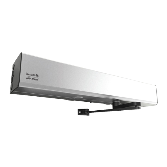
Swing Door Operator (OHC)
Besam SW200i
Installation and Service Manual -
Original instructions
Complies with ANSI/BHMA A156.10 and ANSI/BHMA A156.19 standard for Power
Assist and Low Energy Power Operated Doors.
UL325 & UL991 Listed
1009937-EI-1.0 Issue 2013-02-10
ASSA ABLOY, the global leader in door opening solutions
Advertisement
Table of Contents

Related Manuals for Besam SW200i


Summary of Contents for Besam SW200i
- Page 1 Swing Door Operator (OHC) Besam SW200i Installation and Service Manual - Original instructions Complies with ANSI/BHMA A156.10 and ANSI/BHMA A156.19 standard for Power Assist and Low Energy Power Operated Doors. UL325 & UL991 Listed 1009937-EI-1.0 Issue 2013-02-10 ASSA ABLOY, the global leader in door opening solutions...
- Page 2 © All rights in and to this material are the sole property of ASSA ABLOY Entrance Systems US Inc. AB. Copying, scanning, alterations or modifications are expressly forbidden without the prior written consent of the applicable company within ASSA ABLOY Entrance Systems US Inc.
-
Page 3: Table Of Contents
CONTENTS CONTENTS Revision ..................................... Important information ................................. Technical specification ................................How the Besam SW200i works ............................Models ......................................Operator/Door handing ............................... Part identification ................................... Arm systems ..................................... Options ...................................... Pre-installation ..................................Mechanical Installation ................................ Electrical connection ................................Start-up ...................................... Changing group of parameters ............................ -
Page 4: Revision
1 Revision Revision Following pages have been revised: Page Revision 1.0 This is the first version of the OHC Besam SW200i Installation and Service Manual. Issue 2013-02-10 1009937-EI-1.0... -
Page 5: Important Information
Energy (LE) applications of swing doors. The operator is factory set to Low Energy (LE). The Besam SW200i can be concealed or surface applied on either side of the door for pull or push action, and is suitable for single doors, double doors and double egress doors fitted with swing clear hinges, offset or center pivots. - Page 6 2 Important information turning the equipment off and on, the user is encouraged to try to correct the interference by one or more of the following measures: • Re-orient the receiving antenna. • Relocate the receiver with respect to the equipment. •...
-
Page 7: Technical Specification
Technical specification Manufacturer: ASSA ABLOY Entrance Systems US Inc. Address: 1900 Airport Road, Monroe, NC 28110, US Type: Besam SW200i Power supply: 120 V AC +10/-15%, 50/60 Hz Power consumption: max. 300 W Auxiliary voltage: 24 V DC, max. 700 mA... -
Page 8: How The Besam Sw200I Works
How the Besam SW200i works The swing door operator Besam SW200i uses a DC motor which is connected to the output shaft by a combination of a bevel gear and spur gears. The arm system that is connected to the output shaft opens the door in a wall mounted application. - Page 9 4 How the Besam SW200i works Functions on the basic control unit CU-200 Also see page 53 for more information. 4.4.1 Power failure During power failure the operator acts as a door closer with controlled closing speed. The micro switch located next to the spindle shaft can be adjusted to control when lock kick occurs.
- Page 10 4 How the Besam SW200i works • an open door will not close, if someone steps on the mat • during opening, the door will continue to open, even if someone steps on the mat • during closing, the door will continue to close, even if someone steps on the mat •...
- Page 11 4 How the Besam SW200i works Note! In OFF-position the operator will comply with the Low Energy Regulation. 4.5.6 Program selector (wall mounted) • Input for OPEN, EXIT and OFF (if no program selector, AUTO is default). Note! In OFF-position the operator will comply with the Low Energy Standards if given a KEY impulse.
- Page 12 4 How the Besam SW200i works NO or NC signal • Door indication Used to indicate an open or closed position of the door. The indication position is set by adjusting the inhibit/blanking potentiometer. • Panic bar Parameter group 14, 15 and 16 Issue 2013-02-10 1009937-EI-1.0...
-
Page 13: Models
5 Models Models The Besam SW200i operator can be installed overhead concealed or surface mounted. These two versions can be used in the following installations: • Single doors • Double doors (two operators) Concealed mounted The concealed operator is used to control a center-pivot door, with the operator integrated and concealed in the header above the door. -
Page 14: Operator/Door Handing
6 Operator/Door handing Operator/Door handing Operator handing Concealed Left hand Right hand Left hand Right hand Door handing Door handing is determined by standing with your back to the hinges. The side that the door nor- mally opens (right or left) is the handing of the door. The illustration below shows a right-handed door. -
Page 15: Part Identification
Item Art. No. Description 1008595 End Plate LH OHC Center Pivot 1008588 Head Box Beam Profile Besam SW200i OHC Side Load 1009277 End Plate RH OHC Center Pivot 1701704 M6x30 PFH Thread Forming Screw 93- 09-723187 Screw M6x20... - Page 16 1009278 RH Bottom Load Item Art. No. Description 1008592 Head Box Beam Profile Besam SW200i OHC Bottom Load 1008593 Head Box Cover Profile Besam SW200i OHC Bottom Load 1008612 End Plate OHC Bottom Load 1701704 M6x30 PFH Thread Forming Screw...
- Page 17 7 Part identification Component Mounting Transmission Unit Attach mounting brackets/hardware to transmission unit. Leave mounting bracket hardware loose. Align square nuts into nut run on back of header and slide transmission unit to correct location. With transmission unit in correct location, tighten mounting bracket hardware. Controller Remove (4) M4 X 8 SHCS and (4) oval nuts out of bag and attach to controller, orient oval nuts horizontally.
- Page 18 7 Part identification Junction Box Locate junction box and junction box bracket kit. Remove junction box cover and locate M5 X 10 PHCS. Use screws provided to attach junction box to mounting plate. Use oval nuts (see orientation above) and screws provided to mount junction box to header. Note! For bottom load application, use M5 X 10 PHCS to mount junction box directly to top of header, no mounting plate is required.
- Page 19 7 Part identification Door Stop (Required on all OHC outswing door packages) P/N: 1010090 Use hardware provided to mount door stop to header in order to stop doors at closed position. 1009937-EI-1.0 Issue 2013-02-10...
-
Page 20: Arm Systems
8 Arm systems Arm systems OHC Arm Kit Can be used on OHC, Bottom Load and Readyfold door packages. P/N: 1009345 Offset Pivot Arm Kit / Pull Arm Kit P/N: 1007251 Issue 2013-02-10 1009937-EI-1.0... - Page 21 8 Arm systems Push Arm Kit P/N: 1007241 Pas Arm Kit P/N: 1007247 PAS Arm - RH P/N: 1007476 PAS Arm - LH 1009937-EI-1.0 Issue 2013-02-10...
- Page 22 8 Arm systems Drive shaft extension kits The kits cannot be combined with each other. 5/8" 2-3/4" (16mm) (70 mm) 2" (50 mm) 3/4" (20 mm) P/N: 1008396 BK/SI P/N: 1008398 BK/SI P/N: 1008400 BK/SI P/N: 1009791 Double door installations There are four different types of double door installations: •...
-
Page 23: Options
9 Options Options Push plates For DISABLED or ADA use, mount push plate 31” above floor level. 9.1.1 Push plates PRESS TO OPEN P/N: 75-02-101 P/N: 75-02-102 PRESS TO OPEN P/N: 75-02-107 P/N: 75-02-108 P/N: 75-02-280 9.1.2 Remote transmitter push plates PUSH PUSH PUSH... - Page 24 9 Options Sync cable for double doors (synchronizing of 2 operators) Note! The connection/marking of the sync cable determines which of the operators is the MASTER MASTER SLAVE and SLAVE Black P/N: 331003583 Accessories 3-position switch PS-4C Surface mounting box P/N: 75-15-310 Clear P/N: 655845 P/N: 655806...
- Page 25 9 Options Labels Label kit P/N: 331007317 DO NOT ENTER AUTOMATIC AUTOMATIC DOOR DOOR 75-20-100 75-20-101 Dual Side “AUTOMATIC DOOR / DO NOT ENTER” Out Dual Side “AUTOMATIC DOOR / DO NOT ENTER” In AUTOMATIC CAUTION DOOR 75-20-102 21-24-005 Dual Side “AUTOMATIC DOOR / CAUTION” Dual side "Operator designed for disabled people"...
- Page 26 9 Options Product label P/N: 1008999 Issue 2013-02-10 1009937-EI-1.0...
-
Page 27: Pre-Installation
10 Pre-installation Pre-installation 10.1 Types of installation Concealed Installation The operator may be installed in two types of header (casing): Side Load and Bottom Load. Side Load is the standard type of header. The operator is installed in the header from the side. Bottom Load is used for special applications where side access may be limited (for example, where the finished ceiling is flush with the bottom of the header). - Page 28 Expansion-shell bolt, min. M6x85, UPAT PSEA B10/25, min. 2" (50 mm) from the underside * Besam minimum recommended requirements. Building Codes may give different specifications. Refer to AHJ (Authority Having Jurisdiction). ** Thinner wall profiles must be reinforced with rivnuts.
-
Page 29: Mechanical Installation
11 Mechanical Installation Mechanical Installation 11.1 Installation for Center Pivot Doors 11.1.1 Finding the Pivot Height OH = Door Opening Height DH = Door Height Pivot Height Door Bottom to Receiving Surface of Pivot Socket Header Length FFL = Finish Floor Level a Measure the height of the door (DH). - Page 30 11 Mechanical Installation Issue 2013-02-10 1009937-EI-1.0...
- Page 31 11 Mechanical Installation Door leaf Lock screw Jamb/wall Threshold (optional) Header housing Drive arm 1009937-EI-1.0 Issue 2013-02-10...
- Page 32 11 Mechanical Installation 11.1.2 Installation of Side-Load, Bottom Load & Offset Pivot Header and Operator a Establish the door opening height (OH) and the correct length (L) of the header, see page 29. b Measuring from the highest point on the floor, mark the door opening height on one door jamb. c Use a spirit level and transfer the mark to the opposite jamb.
- Page 33 11 Mechanical Installation 11.2 Offset Pivot Installation - Push The Offset pivot system consists of a main arm, slide track, guide shoe and shaft adapter. All dimen- sions given here correspond to an opening angle of 90-100° operator with push arm on a right- handed door shown (left-handed door mirror image).
- Page 34 11 Mechanical Installation 11.3 Surface Mount Installation The surface mount operator is used to control all types of swing doors. The operator is mounted on either side of the door header, and the door is controlled with a push or PAS/pull arm system. 11.3.1 Models PAS/Pull arm system on a right-handed door shown (header/case side).
- Page 35 11 Mechanical Installation Install and make electrical connections, see page 50. Make all final adjustments (sensors, gaps, etc) to the door package in accordance to ANSI re- quirements. k Re-Install cover. 1009937-EI-1.0 Issue 2013-02-10...
- Page 36 11 Mechanical Installation 11.3.2 Mounting the arm system The push arm system consists of a main arm, telescopic part, arm shoe and shaft adapter. The maximum standard reveal A (see illustration above) is 12” (305 mm). All dimensions given here correspond to an opening angle of 90-100°.
- Page 37 11 Mechanical Installation 10 lbf·ft (14 Nm) Align markings on drive arm and telescopic arm to achieve 40 degrees between the arms. 1009937-EI-1.0 Issue 2013-02-10...
- Page 38 11 Mechanical Installation 11.3.3 Push Arm System Main arm Telescopic part Arm shoe Issue 2013-02-10 1009937-EI-1.0...
- Page 39 11 Mechanical Installation Push Arm System (single) Clearance holes for 1/4” (6 mm) bolts and cable inlet to be drilled on site Offset pivot or butt hinge Pivot/butt hinge centerline Drive shaft centerline 1009937-EI-1.0 Issue 2013-02-10...
- Page 40 11 Mechanical Installation Push Arm System (double) Surface applied dual push Clearance holes for 1/4” (6 mm) bolts and cable inlet to be drilled on site Offset pivot or butt hinge Offset pivot/butt hinge centerline Drive shaft centerline Issue 2013-02-10 1009937-EI-1.0...
- Page 41 11 Mechanical Installation 11.3.4 Surface Mount Installation Pull The pull arm system consists of a main arm, slide track, guide shoe and shaft adapter. The reveal, or distance from the wall line to the door leaf should be standard. All dimensions given here cor- respond to an opening angle of 90-100°...
- Page 42 11 Mechanical Installation Pull Arm System (single) Clearance holes for 1/4” (6 mm) bolts and cable inlet are predrilled (field installation requirements will dictate what type and size hardware to attach header to wall. Offset pivot or butt hinge Adjust during installation Slide Track Drive shaft center line Issue 2013-02-10...
- Page 43 11 Mechanical Installation Pull Arm System (double) Surface applied double pull Clearance holes for 1/4” (6 mm) bolts and cable inlet are predrilled (field installation requirements will dictate what type and size hardware to attach header to wall.) Offset pivot or butt hinge Adjust during installation Slide Track Drive shaft center line...
- Page 44 11 Mechanical Installation 11.3.5 Surface Mount Installation PAS The PAS system consists of a main arm, slide track, guide shoe and shaft adapter. The maximum reveal, or distance from the wall line to the door leaf (A), should not exceed 4 1/4 “ (108 mm). All dimensions given here correspond to an opening angle of 90-100°...
- Page 45 11 Mechanical Installation PAS Arm System (single) Clearance holes for 1/4” (6 mm) bolts and cable inlet are predrilled (field installation requirements will dictate what type and size hardware to attach header to wall. Offset pivot or butt hinge Adjust during installation Slide Track Drive shaft center line 1009937-EI-1.0...
- Page 46 11 Mechanical Installation PAS Arm System (double) Surface applied double pull Clearance holes for 1/4” (6 mm) bolts and cable inlet are predrilled (field installation requirements will dictate what type and size hardware to attach header to wall. Offset pivot or butt hinge Adjust during installation Slide Track Drive shaft center line...
- Page 47 11 Mechanical Installation Slide Track Mounting (Pull/Offset Pivot & PAS Arm) a Locate the door in closed position. b Fix the main arm (2) with guide shoe (1) loose onto the operator shaft so that the guide shoe is just in contact with the door. c During the opening and closing movement of the door, the guide shoe (1) will move a certain distance on the door.
- Page 48 11 Mechanical Installation 11.3.6 Push/Pull Arm System (double egress) Issue 2013-02-10 1009937-EI-1.0...
- Page 49 Right hand 11 Mechanical Installation Surface applied dual egress Click Left hand Clearance holes for 1/4” (6mm) bolts and cable Outer side of 90° inlet to be drilled on site Offset pivot or butt hinge Drive shaft center line Adjust during installation Offset pivot/butt hinge center line 11.3.7 Fixing screw...
-
Page 50: Electrical Connection
12 Electrical connection Electrical connection Note! The installation shall be made according to local codes. When working in, with or around electrical circuits, all power must be disconnected. 12.1 Connection box, single door Fit the connection box in the back plate. Note! To ensure for sufficient grounding, the square nuts must be turned with the teeth upwards against the box so that they cut through the anodizing in the back plate. - Page 51 12 Electrical connection 12.2 Connection box, double doors Re-wiring of Slave Connection box to Master Connection Box Only one power switch is needed to operate two units. Discard the extra switch and use the extra power wires found in cable (1) to route power between connection boxes. Leave the black/white/green wires accessible for the electrician in the box tied to the Master control.
- Page 52 12 Electrical connection k Strip the white (11) and the green (12) wires from cable (1). Leave these two wires unconnected and cut off the remaining black wire (17) from cable (1). Only the following wires should now be unconnected; - white wires (11) + (16) and green earth wires (12) + (14) + (18) - black wire (13) from the Rocker Switch cable m See Installation Manual (1007718), chapter Electrical Connection, section Connection box, how...
- Page 53 12 Electrical connection 12.3 Control units 12.3.1 CU-200 The CU-200 can be equipped with extension units, EXU-SI and/or EXU-SA, depending on the functions required, see page 56 or 57. Encoder Synchronizing of double doors Motor KICK External indicator Panic breakout ON/OFF /HOLD open switch (+) 24 VDC +24V DC...
- Page 54 12 Electrical connection 12.3.2 Arm system selection Factory set arm configuration is PUSH 8 1/4" (210 mm), if other is required: Select arm configuration on the DIP-switches according to the table below. ON=1 OFF=0 Type of arm system Spindle location (hinge to outgoing spindle) AS 1 AS 2 AS 3...
- Page 55 12 Electrical connection 12.3.3 Extension units EXU-SI / EXU-SA Installation To extend the functions, the extension units can be mounted on top of the control unit CU-200, separately or combined. Torx T10 EXU-SA 5 mm nut driver Tag strip EXU-SI long 2 pcs EXU short 1 pc EXU CU-200...
- Page 56 12 Electrical connection 12.3.4 Extension unit EXU-SI Functions This extension unit has inputs for electro-mechanical lock, program selector, batteries, KILL function, OPEN/CLOSE, KEY opening and outer impulse. (+) 24 VDC +24 V DC OPEN Program selector EXIT Unlocked signal from lock KILL reset (see jumper below) KRST KILL impluse...
- Page 57 12 Electrical connection 12.3.5 Extension unit EXU-SA This extension unit has inputs for door mounted sensors, which can give presence impulse on ap- proach side and/or presence detection on swing path side. Relay output for error indication or door indication is also integrated. Functions Monitoring of presence detection/DMPS.SS Monitoring of presence impulse/DMPS.NS...
- Page 58 12 Electrical connection 12.3.6 How to cut the jumper on the sync cable for double doors Note! Connect a cable between Master CU TB1(GND) and Slave CU TB1(GND). MASTER SLAVE Black Function Door design Cut the jumper with color Opening Closing Astragal Jamming...
- Page 59 12 Electrical connection Note! • Locks on the MASTER and SLAVE doors must be connected to the control unit (CU) on the cor- responding operator. • Inner and outer impulses can be connected to either MASTER or SLAVE CU or both. •...
-
Page 60: Start-Up
13 Start-up Start-up The spring pre-tension is factory set to 360° and is normally not necessary to adjust. If adjustment has to be carried out, see “Reducing / Increasing the “Spring pre-tension” (SPTE)” on page 69. Check and adjust the micro switch (1), controlling the lock kick, by turning the black plastic cam (2) when power is off. - Page 61 13 Start-up d Open the door to required open position, plus approx. 5/8” (15 mm), by turning the poten- tiometer SPTE on the CU-200, clockwise. SPTE ≈ 95° 0° e When stop arm is on top of the operator, lift the door stop arm up and mount it on the splines, as close as possible to the stop block 1).
- Page 62 13 Start-up Note! Impulses are not accepted if SPTE is more than 0°. SPTE 0° Door stop arm Stop block Fine-adjustment screw Issue 2013-02-10 1009937-EI-1.0...
- Page 63 13 Start-up 13.2 Auto-learn automatically sets back and latch check (recommended) This learning is performed by pushing the LEARN BUTTON (LRN). • Before the learning procedure starts, make sure that the door has been properly closed i.e., not by force. •...
- Page 64 13 Start-up The doors can also be learned separately before connecting the sync cable. In case of astragal doors and separate learning, the MASTER door must be held open before the SLAVE door learn is carried out. 13.3 General adjustment a Set the hold open time with the potentiometer on the control unit.
- Page 65 13 Start-up 13.4 Connection of activation units and accessories Door mounted Activation With monitoring PS-4C Push sensor DMPS plate OPD/OPS Timer PRESS Kill TO OPEN switches 1 2 3 4 5 CU-200 CU-200 (6 1 EXU-SI 13 3 EXU-SI 3 10 11 12 CU-200 EXU-SA 5 1 2...
-
Page 66: Changing Group Of Parameters
14 Changing group of parameters Changing group of parameters a Disconnect the electrical power contact. b Press the LEARN BUTTON (LRN) and keep it depressed. c Connect the electrical power contact. d Watch the ERROR LED. e Release the LEARN BUTTON after the 5 seconds (LED is out). The ERROR LED flashes a number of short flashes that corresponds to the parameter group number (see table). - Page 67 14 Changing group of parameters 1009937-EI-1.0 Issue 2013-02-10...
- Page 68 14 Changing group of parameters 14.1 Learn with advanced setting of “back- and latch-check” See the prerequisites for performing a “learn” under the heading “Auto-learn automatically sets back and latch check (recommended)” on page 63. a Press the learn button. b Stop the door at the fully open position.
- Page 69 14 Changing group of parameters 14.3 Reducing / Increasing the “Spring pre-tension” (SPTE) The spring pre-tension is factory set to 360° and is normally not necessary to adjust. If adjustment has to be carried out, the electrical power must be switched on during spring pre-tension and learn, see below.
-
Page 70: Classification
15 Classification Classification 15.1 Entering the program mode (classification) On the master control unit. • Disconnect the mains plug • Press the LEARN BUTTON while connecting the mains plug • Watch the ERROR LED • Release the LEARN BUTTON after the second 5 s has passed 15.2 Identify the current classification The ERROR LED flashes an amount of short flashes that correspond to the classification number. -
Page 71: Troubleshooting
16 Troubleshooting Troubleshooting Fault Possible reasons why Remedies/Explanations The door does not open Control switch is set to OFF Change the setting of the control switch The motor does not start Electrical power power is missing Check the electrical power power switch Activation unit does not function Strap impulse inputs Presence detection is activated... - Page 72 16 Troubleshooting 16.1 Error indication • During normal operation the ERROR LED on the control unit is illuminated. • An extinguished LED indicates that there is no electrical power power. • A flashing light on the LED indicates that the operator is out of function (see table below). •...
-
Page 73: Maintenance Plan
The number of service occasions shall be in accordance with national requirements. This is especially important when the installation concerns a fire-approved door or a door with an emergency opening function. Refer to Besam Pro-Active Care option services to learn more about service possibilities! As with all other technical products, an automatic door needs maintenance and service. -
Page 74: Ansi / Bhma A156.10
18 ANSI / BHMA A156.10 ANSI / BHMA A156.10 18.1 REQUIREMENTS FOR POWER OPERATED DOORS From American National Standard for Power-Operated Pedestrian Doors. Please refer to the full standard if necessary, obtainable through BHMA at (212) 661-4261. All figures referred to below can be found in the full standard. - Page 75 18 ANSI / BHMA A156.10 inches, along with an additional sign, visible from the side the zone has been reduced on, stating "AUTOMATIC CAUTION DOOR" as described in 11.2.3. 8.1.2 Motion sensors shall detect a 28 in. minimum high person, moving at a rate of 6 in. per second minimum toward the center of the door within the detection zone described.
- Page 76 18 ANSI / BHMA A156.10 10. Entrapment Protection 10.2 Swinging Doors 10.2.1 The opening time of a swing door to 80 degrees shall not be less than 1.5 seconds 10.2.2 The force required to prevent a stopped power operated swinging door in the last 10 degrees of opening from moving in the direction of opening shall not exceed 30 lbf (133 N) measured 1 in.
- Page 77 18 ANSI / BHMA A156.10 11.2.1 An arrow sign shall be visible from the approach side of a swinging door mounted on the door at a height of 58”+ 5 in. from the floor to the center line of the sign. The sign shall be a minimum of 6 in.
- Page 78 18 ANSI / BHMA A156.10 11.2.3 Swinging doors serving both egress and ingress shall be marked with a decal visible from the swing side of the door, “AUTOMATIC CAUTION DOOR”. The sign shall be mounted on the door at a height 58”+ 5 in. from the floor to the center line of the sign. The sign shall be a minimum of 6 in.
-
Page 79: Ansi / Bhma A156.19 (Low Energy Application)
19 ANSI / BHMA A156.19 (LOW ENERGY APPLICATION) ANSI / BHMA A156.19 (LOW ENERGY APPLICATION) 19.1 REQUIREMENTS FOR POWER OPERATED DOORS The following texts are excerpts from American National Standard for power-operated doors. Please refer to the full standard if necessary. 19.1.1 Activation The operator shall be activated by a knowing act. - Page 80 19 ANSI / BHMA A156.19 (LOW ENERGY APPLICATION) Table II Total Opening Time to 90 Degrees Backcheck at 60 degrees Backcheck at 70 degrees Backcheck at 80 degrees Table I plus 2 seconds Table I plus 1.5 seconds Table I plus 1second If the door opens more than 90 degrees, it shall continue at the same rate as backcheck speed.
- Page 82 ASSA ABLOY Entrance Systems US Inc. AB, 1900 Airport Road, Monroe, NC 28110, US Tel: (704) 290 5520 • Fax: (704) 290 5544 Tel: (877) 237 2687 (service) • Tel: (866) 237 2687 (sale) www.besam-usa.com • marketing.na.besam@assaabloy.com...
Need help?
Do you have a question about the SW200i and is the answer not in the manual?
Questions and answers