
Related Manuals for Vivax Metrotech i5000


Summary of Contents for Vivax Metrotech i5000
-
Page 1: Table Of Contents
i5000 Utility Locating System OPERATIONS MANUAL TABLE OF CONTENTS SAFETY QUICK START GUIDE TECHNICAL SPECIFICATIONS FEATURES SYSTEM OVERVIEW MENU SYSTEM SERVICE AND MAINTENANCE Receiver V2.0 July 29, 2010... - Page 2 Receiver - Operations Manual 2 / 45 ©Metrotech Corporation 2006 – All Rights reserved...
- Page 3 The instrument meets the following standards: EMC-standard : 89/336/EWG (EEC) Electromagnetic compatibility Changing modification rule : 92/31/EWG As well as: Low voltage regulation : 73/23/EWG (EEC) i5000 Receiver - Operations Manual 3 / 45 ©Metrotech Corporation 2006 – All Rights reserved...
-
Page 4: Safety
1 Safety The Metrotech Model i5000 is a series of state-of-the-art utility line locators precisely designed with many powerful features to provide you with optimum information about your locate situation. Included are a system overview, product specifications, quick start procedure for experienced users, and maintenance instructions. - Page 5 To avoid drawing dangerous arcs, switching should only be done in a de-energized condition. The equipment and all accessories must be connected according to applicable standards VDE, EN or DIN as well as country-specific regulations. i5000 Receiver - Operations Manual 5 / 45 ©Metrotech Corporation 2006 – All Rights reserved...
-
Page 6: Quick Start Guide
2 Quick Start Guide for the Experience User 1. Turn the Receiver ON Push the Power ON button to switch on the i5000 receiver. The Metrotech welcome screen is displayed for a few seconds. This screen also displays the model number and the software revision number. - Page 7 The presence of bleedover signals is indicated by the RED color filling the inside of the guidance compass indicator. Figure 2-3 Operational Display Screen i5000 Receiver - Operations Manual 7 / 45 ©Metrotech Corporation 2006 – All Rights reserved...
- Page 8 Press the lower section of the navigation button to compute a depth and current measurement. Depth and current estimates are displayed. Thereafter, the receiver returns to the locating mode. 4-Way Navigation Button Figure 2-4 Depth & Current Measurement Screen i5000 Receiver - Operations Manual 8 / 45 ©Metrotech Corporation 2006 – All Rights reserved...
- Page 9 Indicates the speaker volume setting - from off to high. Volume Bluetooth Indicates an active Bluetooth connection. RS232 Appears when a host serial cable is connected to i5000 receiver. Indicates the receiver can receive signals from 3 or more satellites (optional). i5000 Receiver - Operations Manual 9 / 45 ©Metrotech Corporation 2006 –...
-
Page 10: Technical Specifications
8 ¼” W x 13 ¼” H x 29” L (21.0cm x 33.7 cm x 74.3cm) Weight 4.9 lb ((2.2 kg) Regulatory Compliance FCC, CE Environmental IP54 i5000 Receiver - Operations Manual 10 / 45 ©Metrotech Corporation 2006 – All Rights reserved... - Page 11 Operations manual Hard carrying case 3.2.2 Optional Serial interface cable 12 VDC vehicle adapter rechargeable battery Soft carrying cases Search coil i5000 Receiver - Operations Manual 11 / 45 ©Metrotech Corporation 2006 – All Rights reserved...
-
Page 12: Features
Called Signal Select™, this method both allows detection of galvanically connected reverse (bleedoff) currents, as well as bleedover currents caused by capacitive and inductive coupling. This and other key features of the i5000 receiver are listed below in summary form. - Page 13 4.2 Frequency The active frequency, or the passive band name (power or RF), is always displayed on the top left of the i5000 receiver display. When the frequency soft key is used to change frequency, the display is updated as well.
- Page 14 Care should be taken to determine the effect of other cables in the locate zone that might be creating distortion by carrying bleedover and return currents. Figure 4-6 Distance Sensitive Left/Right Guidance i5000 Receiver - Operations Manual 14 / 45 ©Metrotech Corporation 2006 – All Rights reserved...
- Page 15 4.4 Positive Line ID Positive Line ID is an essential task of a modern locate receiver. The i5000 family incorporates three elements that aid the user in positively identifying the target utility from others that might be carrying the signal because of bleedover or bleedoff. Bleedover is defined as a loss of signal due to capacitive or inductive coupling between lines, and increases in significance with higher frequencies.
- Page 16 Figure 4-8 Distortion Alert Sample Scenario In this particular case, the centerline estimate is not significantly biased, though the depth estimate is less accurate. i5000 Receiver - Operations Manual 16 / 45 ©Metrotech Corporation 2006 – All Rights reserved...
- Page 17 (in the same duct) of the target conductor. In this case, the predominant current that is detectable at the surface is from the bleedover line, but the actual centerline estimate is correct. i5000 Receiver - Operations Manual 17 / 45...
- Page 18 When the Depth button is pressed, the receiver averages the signal strength for a few seconds and displays the results. Figure 4-10 Depth Measurement Interface i5000 Receiver - Operations Manual 18 / 45 ©Metrotech Corporation 2006 – All Rights reserved...
- Page 19 When the i5000 receiver data logging option is activated, the operator may press the <Mark> soft key to mark a particular data point as a valid entry into the log file. Depth measurements only taken to help the operator understand the field conditions of the locate site should not be marked using the <Mark>...
- Page 20 Bluetooth can also be stored and filed with the corresponding locate data. If a GPS antenna is installed on the i5000 receiver, locate coordinate data – latitude, longitude, and GPS clock time are recorded as well.
-
Page 21: System Overview
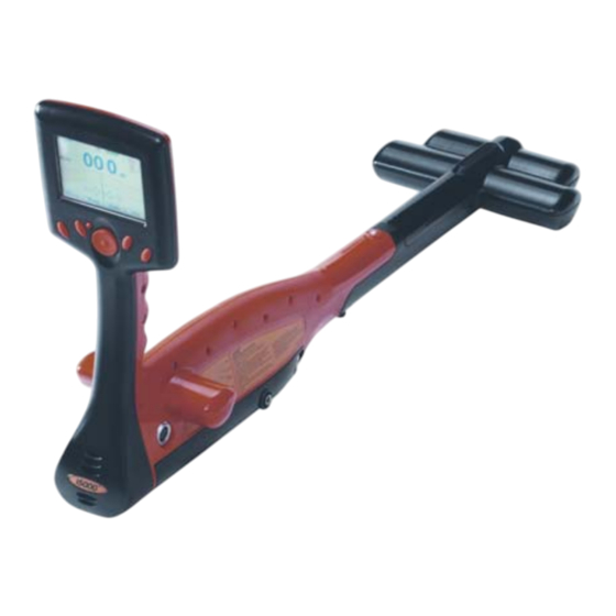
5.1 Top View The i5000 receiver includes a colorful graphical display, a 4-way navigation button, and four soft keys for operation and setup modes. A separate Power ON button, located near the navigation button, provides easy access to activate power. - Page 22 5.1.1 Operational Display Screen The i5000 receiver operational screen is a ¼ VGA bright color graphical display. Two screens are displayed to the user – locate mode and measurement. Numerical Field Signal Strength Distance Sensitive Left/Right Guidance™ Figure 5-2 Locate Mode Display Screen...
- Page 23 Indicates the speaker volume setting - from off to high. Volume Bluetooth Indicates an active Bluetooth connection. RS232 Appears when a host serial cable is connected to i5000 receiver. Indicates the receiver can receive signals from 3 or more satellites (optional). i5000 Receiver - Operations Manual 23 / 45 ©Metrotech Corporation 2006 –...
- Page 24 5.2 Side Views The i5000 is equipped with a smart accessory connector and battery pack, accessible from the receiver’s right side panel. ⓑ ⓐ ⓒ Figure 5-4 i5000 Side View Side View Legend GPS antenna (optional) Smart Connector Battery Pack Receptacle 5.2.1 Battery Pack...
- Page 25 Excess heat can damage batteries, causing a rupture or ignition. Do not place batteries near fire, heat, or in direct sunshine. 2. Attach the i5000 mains power supply to the charging jack of the Li-ion battery pack. 3. Plug the power supply into the electrical outlet.
-
Page 26: Menu System
6 i5000 Menu System The receiver’s menu system includes six (6) selectable menus for configuring the i5000. Press the <Menu> soft key from the operational display screen to access the main menu. 6.1 Main Menu To access the main menu, press the <Menu> soft key from the operational display screen. - Page 27 Press the <Select> soft key to activate or deactivate specific or all frequencies. Deactivating frequencies does not permanently remove these from the i5000 receiver. Access the frequency menu to reactivate them.
- Page 28 Press the <Select> soft key to activate or deactivate specific or all frequencies. Deactivating frequencies does not permanently remove these from the i5000 receiver. Access the frequency menu to reactivate them.
- Page 29 Figure 6-7 RF Selection Screen in Frequency Menu 6.1.2 Mode Menu The i5000 receiver has two locate modes - line locate and sonde locate. To access the locate mode menu, use the 4-way navigation button to highlight Mode chosen menu is labeled at the top of the menu screen.
- Page 30 Press the <Select> soft key to select the desired mode. Press <Back> to return to the previous display screen. Figure 6-10 Sonde Locate Selection Screen in Mode Menu i5000 Receiver - Operations Manual 30 / 45 ©Metrotech Corporation 2006 – All Rights reserved...
- Page 31 Press the <Select> soft key to open the desired menu screen. Press <Back> to return to the operational display screen. Use the 4-way navigation button to select another menu. Figure 6-11 Settings Menu Selection 6.1.3.1 Personalize The operator can control certain user interface elements of the i5000 receiver. Available choices are: Distortion Number ...
- Page 32 6.1.3.2 Audio The Audio menu controls the i5000 receiver audio output characteristics. Use the 4-way navigation button to move up and down the settings list. Use the 4-way navigation button to move right and highlight the audio options. Press the <Select> soft key to toggle through the different speaker volume settings –...
- Page 33 Figure 6-14 Initial Settings Selection in Settings Menu The i5000 supports various languages – English, Spanish, French, and German. To reset the menu system to the desired language, use the 4-way navigation button to highlight the Language option.
- Page 34 6.1.3.5 Preset State The Preset State menu option allows the operator to restore the i5000 receiver user interface configuration to factory default settings for all menu selections in just one simple operation. Selecting the Preset State function does not result in any loss of receiver capability, the choice of available frequencies, or the loss of any data stored in the data logging memory.
- Page 35 6.1.3.6 About The About screen displays important information about the i5000 receiver's software and hardware configuration. Use the 4-way navigation button to move up and down the settings list. Press the <Select> soft key to choose the About option. Press the <Back> soft key to return to the previous display screen.
- Page 36 The Bluetooth wireless connection allows Bluetooth-enabled devices to communicate with the i5000 receiver. Data and digital photos can be saved in memory and transferred via Bluetooth wireless communication to laptop computers or PCs. The reverse is also available - locate ticket information and digital photos may be loaded into the i5000 memory.
- Page 37 Options Selecting Factory Preset resets certain internal Bluetooth settings to factory defaults. Make sure the i5000 receiver Bluetooth Setting is in the OFF position before entering any telecommunications central office or other telecommunications data transmission infrastructure. Figure 6-25 Options in Bluetooth Settings Menu...
- Page 38 6.1.4.4 Paired Devices i5000 transmitters are equipped with Bluetooth transmission capabilities. The paired devices menu allows the user to mate up to six transmitters to a single receiver. If a receiver is within 30 ft. (9 m) of a transmitter and Bluetooth transmission is ON for both instruments, the receiver logs the output power conditions and active frequencies every 30 sec.
- Page 39 Figure 6-30 Adjust Volume Selection in Shortcuts Menu Selecting Backlight Power places the shortcut to Backlight Power (BL). Figure 6-31 Backlight Power Selection in Shortcuts Menu i5000 Receiver - Operations Manual 39 / 45 ©Metrotech Corporation 2006 – All Rights reserved...
- Page 40 Press the <Select> soft key to open the menu. Press the <Back> soft key to return to the previous display screen. Figure 6-34 Tickets Selection in Data Logging Menu i5000 Receiver - Operations Manual 40 / 45 ©Metrotech Corporation 2006 – All Rights reserved...
- Page 41 The Ticket Information header indicates the open or closed status. Selecting <Open> opens the ticket to logging additional data. Press the <Back> soft key to return to the previous display screen. Figure 6-37 Ticket Information in Tickets Menu i5000 Receiver - Operations Manual 41 / 45 ©Metrotech Corporation 2006 – All Rights reserved...
- Page 42 4-way navigation button to highlight Log Memory and press the <Select> soft key to display the log data statistics. Figure 6-39 Log Memory Selection in Data Log Menu i5000 Receiver - Operations Manual 42 / 45 ©Metrotech Corporation 2006 – All Rights reserved...
- Page 43 6.1.6.2.1 Data Log Memory The Data Log Memory screen lists the status of the i5000 receiver memory. Press the <Back> soft key to return to the previous display screen. Figure 6-40 Data Log Memory in Data Logging Menu 6.1.6.2.2 Data Log Pictures Selecting Pictures displays the name and size of all Locate Images in memory.
-
Page 44: Service And Maintenance
The i5000 receiver is designed for rugged outdoor use, but rough handling should be avoided. Keep the equipment dry, clean, and free of grit. Store the i5000 (in a dry carrying case) in a cool, dry place. Do not expose to excessive temperatures. - Page 45 Metrotech Corporation. ® Bluetooth is a registered trademark of Bluetooth SIG Inc. © Metrotech Corporation 2006 - All Rights Reserved i5000 Receiver - Operations Manual 45 / 45 ©Metrotech Corporation 2006 – All Rights reserved...
Need help?
Do you have a question about the i5000 and is the answer not in the manual?
Questions and answers