Advertisement
SOYAL
ACCESS & INDUSTRIAL CONTROL
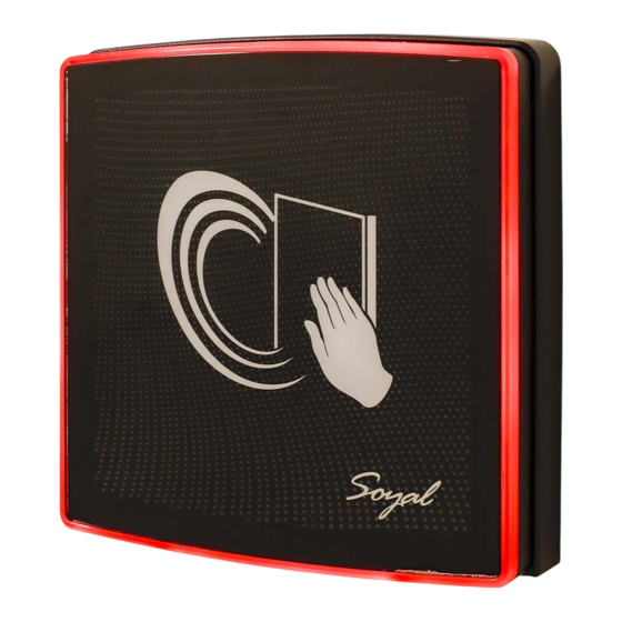
AR-888-PBI: Touchless Infrared Button - LED Ring (Standard: Green/Red ; By Order: Blue/Red)
Product (US/EU)
1
Connector Table / Dip_switch
J2 J1
LED status
4
adjustment
CN1
Connector:
Function
Cable
Color
Relay COM
1
Green DC24V / 1A
N.O.
2
Blue
N.C.
3
Purple DC24V / 1A
Power
4
Black
5
Red
Wiring Diagrams
Controller
Touchless Infrared Button
2
Tools
Bottom Cover
Sensing distance
3
adjustment
Dip_switch
2
1
Connector
Description
DC24V / 1A
DC 0V
DC 9-24V
Electric Strike
or
Electric Bolt
Magnetic Lock
N.C.
COM
PB
V+
GND
V+
POWER
GND
9-24VDC
AR-888-PBI
Flat Head Hex Socket
Allen key
Screw: M3x8
2MM / 48*15MM
Dip_switch Output Mode
2
ON
ON
1
2
1
2
#1
#2
ON
ON
1
2
1
2
#3
#4
Sensing distance adjustment
3
LED status adjustment
4
Standby
Motion
mode
NC NO
J1(LED G)
J2(LED R)
(Example #2)
N.O.
COM
N.C.
V+
V+
GND
V-
Easy Install Kit (By Order)
3
A.
MPLA-888XA18/19 (US / EU)
SW1
SW2
※1
ON
ON
2
ON
OFF
3
OFF
ON
4
OFF
OFF
Turn around
Sensing distance
Clockwise
Sensing distance is greater
Counterclockwise
Sensing distance is smaller
Standby mode
1
LED G(Green)
※2
LED R(RED)
LED GR
3
(Green/RED)
4
--
POWER
GND
9-24VDC
COM
N.O.
N.C.
V-
V+
Request To Exit
AR-888-PBI
V210908
※Default Value
OUTPUT
Pulse
Delay 3 Sec.
Latch
Delay 6 Sec.
※Default Value
Motion
LED R(RED)
LED G(Green)
--
LED GR
(Green/RED))
Advertisement
Table of Contents

Related Manuals for Soyal AR-888-PBI


Summary of Contents for Soyal AR-888-PBI
- Page 1 AR-888-PBI SOYAL Touchless Infrared Button V210908 ACCESS & INDUSTRIAL CONTROL Installation AR-888-PBI: Touchless Infrared Button - LED Ring (Standard: Green/Red ; By Order: Blue/Red) Easy Install Kit (By Order) Product (US/EU) Tools Bottom Cover Flat Head Hex Socket Allen key...
- Page 2 SOYAL V210908 ACCESS & INDUSTRIAL CONTROL Installation Pull the cables from the square holes of the eva foam gasket and mounting plate. Use a screwdriver to screw the mounting plate B onto the wall with Flat Head Cap Philips Tapping Screws (Excluded, the Installer should prepare before installation.
Need help?
Do you have a question about the AR-888-PBI and is the answer not in the manual?
Questions and answers