Table of Contents
Advertisement
Quick Links
50kW-55kW
PTO GENERATORS
GENERATORS
INSTALLATION & OPERATORS
MANUAL
COPY YOUR MODEL AND SERIAL NUMBER HERE
No other WINCO generator has the same serial number as yours.
If you should ever need to contact us concerning this unit, it will
help us to respond to your needs faster.
MODEL __________________________________________________
SERIAL NUMBER _________________________________________
PURCHASE DATE _________________________________________
DEALER NAME ___________________________________________
DEALER PHONE # ________________________________________
Advertisement
Table of Contents

Related Manuals for Winco 55PTOC4-18/1


Summary of Contents for Winco 55PTOC4-18/1
- Page 1 MANUAL COPY YOUR MODEL AND SERIAL NUMBER HERE No other WINCO generator has the same serial number as yours. If you should ever need to contact us concerning this unit, it will help us to respond to your needs faster.
-
Page 2: Table Of Contents
Should you experience a problem please follow the “Troubleshooting Tables” near the end of this manual. INSTALLATION The warranty listed in the manual describes what you can FOUNDATION MOUNTING expect from WINCO should you need service assistance in TRAILER MOUNTING the future. THREE-POINT HITCH KIT ELECTRICAL CONNECTIONS... -
Page 3: Safety
SAFETY WARNING: FIRE HAZARD IMPORTANT SAFETY INSTRUCTIONS Gasoline and other fuels present a hazard of possible This engine generator set has been designed and explosion and/or fire. manufactured to allow safe, reliable performance. Poor maintenance, improper or careless use can result in A. -
Page 4: Specifications
Required Tractor PTO HP 100 Required Tractor PTO HP 100 Gear Lube Gear Lube Volume 0.875 Pint Volume 0.875 Pint Type SAE 80-90W-140 Type SAE 80-90W-140 50PTOC4-04/1 55PTOC4-18/1 Watts 50,000 Watts 55,000 Volts 120/208 Volts 277/480 Phase Three Phase Three... -
Page 5: Introduction
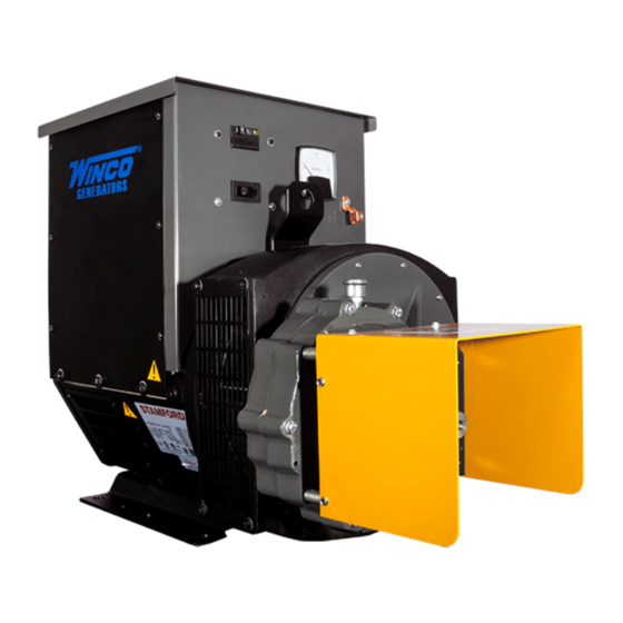
The WINCO power take-off generators are designed primarily for farm use as a standby electrical power supply, utilizing the power take-off of a tractor or truck as the prime mover. -
Page 6: Preparing The Unit
1. As you receive your unit, it is critical to check it for any damage. If any damage is noted, it is always easiest to refuse the shipment and let WINCO take care of the freight claim. If you sign for the unit, the transfer of the ownership requires that you file the freight claim 2. -
Page 7: Installation
INSTALLATION FOUNDATION MOUNTING A. The trailer construction must be strong enough to support the generator. B. The design of the trailer must enable the trailer to remain stable during operation, and to resist tipping caused by generator starting and reflected load torque. C. -
Page 8: Electrical Connections
The manual transfer switch must in all cases be Your WINCO portable generator ships with a bonded equal to or greater than the rating of the entrance rated neutral. You can safely use this generator without external breaker. - Page 9 Three Phase 277/480V WINCO recommends a 1 GA wire size for these units. If a smaller gauge is desired, you will need to use bushings for the three-phase units. Bushings do come standard with the 480V Anderson Connection plug kit.
-
Page 10: Typical Connection Methods For Generator Power Service
TYPICAL CONNECTION METHODS FOR GENERATOR POWER SERVICE IMPORTANT: When making standby service hook up, make sure load to be transferred to standby generator will not exceed generator rating. TYPICAL HOOK UP FOR TYPICAL HOOK UP FOR SUPPLYING ALL CIRCUITS SUPPLYING ONLY ESSENTIAL CIRCUITS WITH EMERGENCY POWER WITH EMERGENCY POWER To Power Line Master Switch... -
Page 11: Operation
OPERATION OUTPUT POWER AVAILABLE AND LOAD DETERMINATION Before using the generator, read and understand the following information. Generator output current (amperage) is internally limited by three circuit breakers. If too much demand is placed on a generator output (if you try to drive too many motors with it, for example), one of the circuit breakers will trip, cutting off the output in order to protect the generator. -
Page 12: Pre-Start Checks
PRE-START CHECKS WARNING: PERSONAL INJURY DANGER: PERSONAL INJURY When working on or around these generators, do not wear Power take-off must be DISENGAGED at this time. loose fitting clothing or any articles that may get caught in moving parts. 4. Couple the tractor to the generator with the drive shaft (tumbling bar). -
Page 13: Generator Procedures
GENERATOR PROCEDURES 4. Shut off the engine. START-UP 5. Disconnect drive shaft. Power take-off end first, then the 1. With the power take-off drive disengaged, start the generator end. engine which will drive the generator. Run the engine long enough to warm it up before proceeding, so that it will run smoothly and achieve full power under generator load. -
Page 14: Maintenance
MAINTENANCE The generator input shaft should be cleaned and lubricated GENERAL INFORMATION with a thin film of grease before installing the drive shaft and each time it is removed. The main components of the generator are: rotor and stator assembly, cooling fan, brushes, brush holder assembly, The drive shaft (tumbling bar) requires greasing. -
Page 15: Cleaning & Inspection
2. Remove oil level check plug. Oil Level Plug 3. Remove the oil drain plug, drain the oil into a clean oil resistant container, 1 quart or larger. Check the oil for metal. Fine metal dust in the oil does not indicate trouble, but metal chips do. -
Page 16: Trouble Shooting Table
TROUBLE SHOOTING TABLE SYMPTOM POSSIBLE CAUSE CORRECTIVE ACTION Low Output Voltage 1. Engine speed too slow. 1. Check engine speed. Increase RPM if necessary. 2. Generator overloaded. 2. Reduce load if it is higher than the rated capacity of the 3. -
Page 17: Wiring Diagram
WIRING DIAGRAM 120/240V SINGLE PHASE BACK VIEW OPM-137/D... -
Page 18: 120/208V & 120/240V Three Phase
120/208V & 120/240V THREE PHASE BACK VIEW OPM-137/D... -
Page 19: 277/480V Three Phase
277/480V THREE PHASE BACK VIEW OPM-137/D... -
Page 20: 36 Month Limited Warranty
36 MONTH LIMITED WARRANTY WINCO, Inc., warrants for thirty-six months from date of shipment, that it will repair or replace at its option, for the original user, the whole or any part of the product found upon examination, by WINCO at its factory at 225 South Cordova Avenue, Le Center, Minnesota, or by any factory-authorized service station, to be defective in material or workmanship under normal standby use (average less than 50 hours per month) and service.
Need help?
Do you have a question about the 55PTOC4-18/1 and is the answer not in the manual?
Questions and answers