
Related Manuals for Winco DE50F4 1 Series


Summary of Contents for Winco DE50F4 1 Series
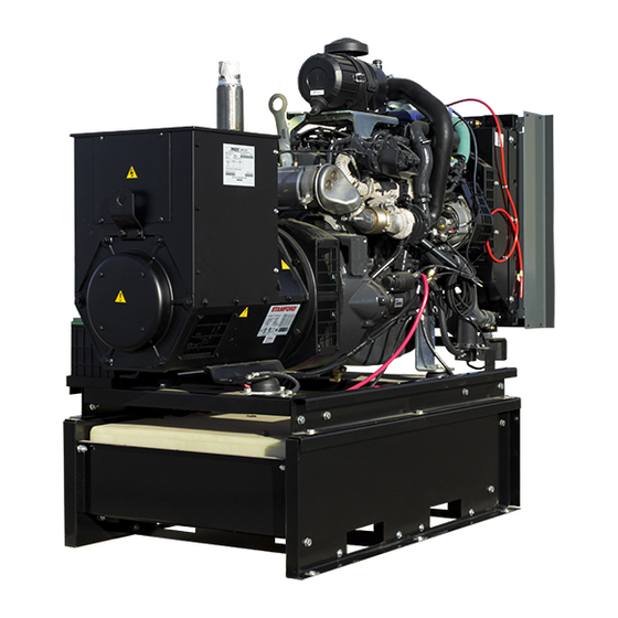
- Page 1 DE50F4-XX / 1 DE50F4-XX / 4 DE50F4-XX/5 GENERATORS GENERATOR AN AMERICAN COMPANY INSTALLATION AND OPERATORS MANUAL www.wincogen.com...
-
Page 2: Table Of Contents
TABLE OF CONTENTS SAVE THESE INSTRUCTIONS ENGINE CODES SAFETY INFORMATION WIRING SIZE TABLE SAFETY DEFINITIONS ENGINE HARNESS SPECIFICATIONS CONTROL PANEL WIRING DIAGRAM 30 DE50F4 DSE7310 WIRING DIAGRAM INTRODUCTION GENERATOR CONNECTIONS TESTING POLICY CA EMISSION CONTROL STATEMENT 34 Rated output of generator is based on engineering tests US ENVIRONMENTAL STATEMENT of typical units, and is subject to, and limited by, the REVALIDATION OF WARRANTY... -
Page 3: Save These Instructions
COPY YOUR MODEL AND SERIAL NUMBER HERE No other WINCO generator has the same serial number as yours. If you should ever need to contact us on this unit, it will help us to respond to your needs faster. -
Page 4: Safety Information
SAFETY INFORMATION B. Keep fuel containers out of reach of children. SAVE THESE INSTRUCTIONS C. Do not smoke or use open flame near the generator set or fuel tank. This engine generator set has been designed and D. Keep a fire extinguisher nearby and know its proper manufactured to allow safe, reliable performance. -
Page 5: Specifications
SPECIFICATIONS DE50F4 STANDBY PRIME VOLTS WATTS AMPS WATTS AMPS 120/240 1-PH 45,000 40,500 40.5 120/208 3-PH 47,000 43,200 120/240 3-PH 47,000 43,200 277/480 3-PH 47,000 43,200 346/600 3-PH 47,000 43,200 GENERATOR RESISTANCE (all value at 22°C) Model Stamford UCI224E Winding Group Rotor 0.69 Ω... -
Page 6: Testing Policy
Go to the WINCO website for a list of engine dealers temperature, altitude, fuel, and other conditions specified (wincogen.com) or contact the WINCO Service Department. -
Page 7: Preparing The Unit
This must be completed and tank, making for a DANGEROUS, unbalanced lifting load. returned to WINCO Inc. within 180 days of the factory If the generator was shipped on the fuel tank, use the invoice date. If this form is not returned, the Warranty may lifting points located on the fuel tank to move the entire be voided. -
Page 8: Installation
The radiator or duct flange should not be placed closer than 0.75 in. to the edge of the structure or other solid surfaces. The WINCO installation manual OPM-112 contains The radiator is mounted on rubber vibration isolators that additional information on indoor installations and allow it to move. -
Page 9: Exhaust Installation
EXHAUST INSTALLATION INSTALLING THE FUEL LINE WARNING: PERSONAL INJURY Engine-generator sets are properly adjusted before they leave the factory. Connecting a fuel supply with adequate Improper exhaust installation will allow dangerous gases supply volume is critical to reliable operation. Diesel units to seep into enclosed spaces causing a hazard to your with optional base mounted fuel tanks are pre-plumbed to health and/or death. -
Page 10: Load Balancing
LOAD BALANCING The wire must be properly sized between the generator and the load. Use the table 310-16 of the National Electrical Code ANSI/NFPA 70. to properly size the wire to meet or The following diagram represents this generator when exceed the amperage rating of the circuit breaker installed. -
Page 11: Grounding
DC WIRING VEHICLE-MOUNTED GENERATOR All communication and DC wiring should be run in Your WINCO generator ships with a bonded neutral. separate conduit from AC wiring. When mounted to a vehicle to safely distribute power it is necessary that the generator frame is bonded to the vehicle To install the wires, reference the following picture. -
Page 12: Installing The Battery
DSE configuration software to the positive cable. enable the commutation. Contact Winco service for a list of 5. Be sure all connections are tight and coat the register values. -
Page 13: Servicing Batteries
SERVICING BATTERIES Batteries used on these units may, over time, lose water. This is especially true if you are using a trickle charger to maintain your battery. When refilling the battery with water, use only distilled water. Tap water will shorten the service life of the battery. -
Page 14: Starting Procedure
We have partnered with a national lubrication oil dipstick (1) using a clean cloth and then put it back into manufacturer to give you access to Winco private branded its seat (2). Remove the dipstick (1) again and check the premium oil available at comparable prices to conventional level. -
Page 15: Manual Start Panel
MANUAL START PANEL Low fuel lamp will be steady when fuel level has reached 20% or less. It will flash when the fuel level is 5% or less. (Standard) The engine will shut down if the fuel level is at 5% or less. This generator comes standard with a manual start control In the event that the upper left and upper right icons are panel. -
Page 16: Dse7310 Mkii
DSE7310 MKII WARNINGS Warnings are non-critical alarm conditions. They do not (Optional) affect the operation of the generator system, they serve to draw the operator’s attention to an undesirable CAUTION condition. Warning alarms are self-resetting when the If the DSE7310 is being replaced with a manual start panel, fault condition is removed. -
Page 17: Control Power
With the engine running smoothly check the no load voltage and frequency on the digital display. The voltage should match the nameplate and a frequency of 59.5 to 60.5 hertz (Hz). If you have the proper voltage at the generator the next step is to check the voltage at the generator terminals in the Automatic Transfer Switch. -
Page 18: Operating Conditions
OPERATING CONDITIONS NORMAL OPERATION This generator set is designed to be operated under load and the accumulation of operating hours without load can cause unburned fuel from the combustion chamber to build up in the exhaust system. This is called wet stacking and can result in fouled injectors and carbon buildup in the exhaust pipes, turbo and exhaust valves. -
Page 19: Maintenance
6. Using the oil filter wrench, further tighten the oil filter. weather. We have partnered with a national lubrication oil manufacturer to give you access to Winco private branded REFILLING COOLANT premium oil available at comparable prices to conventional oils. -
Page 20: Checking Water In Pre-Filter
3. Position the filter (5) in its seat. Using Illustration 2: 4. Replace the cover (4) of the air filter and lock it in place using the two quick release hooks (3). 1. Loosen the nut (2) 2. Disconnect the fittings (1)(4). 3. -
Page 21: Maintenance Schedule
TROUBLE SHOOTING TABLES 4. Connect the fuel circuit to a tank containing CFB protective liquid (ISO 4113) and introduce the liquid by Problem Possible Causes pressurizing the circuit and driving the engine for approx. 2 min. after excluding injection system Unit will not crank when Digital genset not in AUTO operation. -
Page 22: Engine Codes
ENGINE CODES FMI Test Translation The electrical Signal of the EGR Valve position sensor is monitored. In case of defect recognition a replacement value is 1B-3 taken. The electrical Signal of the EGR Valve position sensor is monitored. In case of defect recognition a replacement value is 1B-4 taken. - Page 23 FMI Test Translation The Fuel Rail pressure control is executed with a device: Metering Unit (MeUn) as feeding quantity control and an 9D-12 overpressure valve allocate in the rail (PRV). Dataset Interlock Feature is used to prevent the flashing of unintended datasets on to the ECU during any SW upgrades A6-2 in field.
- Page 24 FMI Test Translation Hardware errors in the injectors and respective ECM power stages are investigated. Diagnostic procedure uses pattern detection to identify specific errors and trigger appropriate substitute reaction. The behavior pattern describes in a 28C-5 bit mask different detected problem (overcurrent, command collision, RAM error,short circuit,..) when the expected combination of errors is detected (measured and reference pattern are matching) a failure is detected.
- Page 25 FMI Test Translation Engine Starter is controlled by two relays actuators one for Low Side and one for High Side. Both power stages are 2A4-6 monitored by Hardware for electric failures. The Engine Position Management module is responsible for signals from camshaft and crankshaft sensor evaluation: angle and speed determination, signal plausibility and quality are monitored by this module.
- Page 26 FMI Test Translation The Power stage of EGR Valve actuator is monitored by Hardware for electric failures. The Power stage of electric EGR Valve actuator (H-Bridge) is monitored by Hardware for electric failures. The H-Bridge has 2 switches (High side and Low side). Each circuit is monitored separately. The Power stage of electric EGR Valve actuator (H-Bridge) is monitored by Hardware for electric failures.
- Page 27 FMI Test Translation 4009 The Power stage of Fuel Filter heater is monitored by Hardware for electric failures. FA9-5 4009 The Power stage of Fuel Filter heater is monitored by Hardware for electric failures. FA9-6 The electrical Signal of the Oxi Cat temperature upstream sensor is monitored. In case of defect recognition a substitute 4765 129D-3 value is taken.
-
Page 28: Wiring Size Table
WIRING SIZE TABLE The table below is based on Table 310.15 (B) (16) in the National Electric Code 2014 edition. Allowable ampacitier of insulated conductors rated 0 through 2000V, 75°C through 90°C. Not more than three current-carrying conductors in Raceway, Cable, or Earth (direct buried). Adjust for 40°C (104°F) ambient temperature. -
Page 29: Engine Harness
ENGINE HARNESS OPM-143/I... -
Page 30: Control Panel Wiring Diagram
CONTROL PANEL WIRING DIAGRAM OPM-143/I... -
Page 31: Dse7310 Wiring Diagram
DSE7310 WIRING DIAGRAM OPM-143/I... -
Page 32: Generator Connections
GENERATOR CONNECTIONS THREE PHASE AC WIRE HIGH AND LOW WYE OPM-143/I... - Page 33 THREE PHASE AC WIRING- DELTA SINGLE PHASE 311 WINDING OPM-143/I...
- Page 34 CALIFORNIA EMISSION CONTROL WARRANTY STATEMENT YOUR WARRANTY RIGHTS AND OBLIGATIONS California Air Recourses Board and FPT Industrial S.p.A. are pleased to explain the emission control system warranty on 2021 to 2023 off-road engines. In California, new heavy-duty off-road engines must be designed, built, and equipped to meet the state’s stringent anti-smog standards.
-
Page 35: Environmental Statement
US ENVIRONMENTAL WARRANTY STATEMENT FPT Industrial S.p.A. warrants to the ultimate purchaser and each subsequent purchaser that the engine is designed, built, and equipped so as to conform with US Environmental Protection Agency (EPA) regulations applicable at the time of manufacture and that it is free from defects in workmanship or material which would cause it not to meet these regulations for a period of time: 2 years or 1,500 hours of operation, whichever occurs first, for engines less than 19kW (25HP) 5 Years or 3,000 hours of operation, whichever occurs first, for engines greater than or equal to 19kW (25 HP) -
Page 36: Revalidation Of Warranty
(12) months afterwards for a maximum of twenty-four (24) months for warranty coverage to be available, and provide written confirmation to WINCO inc that the engine was revalidated. Warranty will be exhausted if the unit is still in the seller’s inventory after revalidation cycle. -
Page 37: Limited Warranty
Air cooled units purchased for stock have 1 year to be sold. The warranty to the original retail customer commences on the date of sale of the product to them. All liquid cooled units have 180 days from the Winco invoice to submit a start up date. - Page 38 Standby use is defined as an application where utility power is present -and- the generator set is used as emergency backup during utility power outages. WINCO reserves the right to change or improve it’s products without incurring any obligations to make such changes or improvements on products purchased previously.
- Page 39 22. Travel time or service calls unless specifically authorized by Winco, Inc. in writing. GENERAL INFORMATION The WINCO, Inc. Service Department is open from 7:30 AM to 4:30 PM Central Standard time. It is located at 225 South Cordova Ave., Le Center, MN, 56057-1805. Phone Numbers: Service Department - 507-357-6831 FAX Line - 507-357-4857.
- Page 40 GENERATORS AN AMERICAN COMPANY 225 S. CORDOVA AVE • LE CENTER, MN 56057 Sales: 507-357-6821• sales@wincogen.com Service: 507-357-6831 • service@wincogen.com www.wincogen.com OPM-143/I...
Need help?
Do you have a question about the DE50F4 1 Series and is the answer not in the manual?
Questions and answers