Table of Contents
Advertisement
Quick Links
Advertisement
Table of Contents

Related Manuals for Fuji Electric EconoPACK+


Summary of Contents for Fuji Electric EconoPACK+
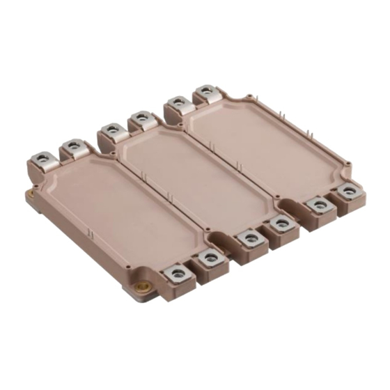
- Page 1 Industrial IGBT Module EconoPACK™+ (M629) Mounting Instruction Note) EconoPACK + is a registered trademark of Infineon Technologies. July 2022 MT5Q03980 MT5Q1070c © Fuji Electric Co., Ltd. All rights reserved. © Fuji Electric Co., Ltd. All rights reserved.
-
Page 2: Table Of Contents
3. Main terminal connection 3-1. Bus bar connection 3-2. Maximum allowable mechanical force when connecting to bus bar 4. PCB mounting instruction 4-1. Soldering of PCB 4-2. Screw fastening of PCB MT5Q1070c © Fuji Electric Co., Ltd. All rights reserved. -
Page 3: Scope Of Application
When handling the module, in addition to the contents described in this document, please check the Warning and Caution in the module’s specification too. Note) EconoPACK + is a registered trademark of Infineon Technologies. MT5Q1070c © Fuji Electric Co., Ltd. All rights reserved. -
Page 4: Mounting The Module To Heat Sink
(b) In the case of concave shape Thermal grease P=100mm pitch application surface 50μm (Heat sink) (c) In the case of both shapes exist Figure 1. Heat sink surface flatness and roughness MT5Q1070c © Fuji Electric Co., Ltd. All rights reserved. -
Page 5: Application Of Thermal Grease
>= 1 μm Thermal grease thickness 100 +/- 30 Thermal grease (apply to module’s base plate) Stencil mask Stencil mask fixing tool Squeegee (for applying thermal grease) Figure 2. Thermal grease application MT5Q1070c © Fuji Electric Co., Ltd. All rights reserved. -
Page 6: Screw Fastening To Heat Sink
2.5~3.5Nm. Tightening torque Tightening sequence Temporary tightening 1/3 of the final tightening torque (1)→(2)→(3)→(4)→(5)→(6)→(7)→(8) Final tightening 2.5~3.5Nm (1)→(2)→(3)→(4)→(5)→(6)→(7)→(8) Figure 3. Tightening torque and tightening sequence MT5Q1070c © Fuji Electric Co., Ltd. All rights reserved. -
Page 7: Main Terminal Connection
500 N 5 Nm 5 Nm 500 N 1000 N (a) Horizontal direction * Short period force applied during mounting process (b) Vertical direction Figure 4. Maximum allowable force for each direction MT5Q1070c © Fuji Electric Co., Ltd. All rights reserved. -
Page 8: Pcb Mounting Instruction
Figure 7(b). 7.0 ~ 10.0mm Module 2.4~2.6mm 2.4~2.6mm 2.4 ~ 2.6mm (a) Recommended screw dimension (diameter) (b) Recommended screw dimension (length) and mounting image Figure 5. Recommended screw dimensions and mounting image MT5Q1070c © Fuji Electric Co., Ltd. All rights reserved. - Page 9 Final tightening 0.4±0.05 Nm (1)→(2)→(3)→(4)→(5)→(6)→(7)→(8) Figure 6. Tightening torque and tightening sequence (a) Example of screw in tilted state (b) Example of mechanical damage Figure 7. Poor example of screw tightening MT5Q1070c © Fuji Electric Co., Ltd. All rights reserved.
- Page 10 Please consider and decide the installation process. The applications described in this manual are illustrative of typical applications using Fuji Electric's semiconductor products. This manual do not warrant or grant licenses for the enforcement of industrial property rights or other rights.
- Page 11 (4) Operating environment If the product is used in an environment exposed to acids, organic substances, and corrosive gases (hydrogen sulfide gas, sulfuric acid gas, etc.), the product’s performance and appearance may deteriorate. MT5Q1070c © Fuji Electric Co., Ltd. All rights reserved.
Need help?
Do you have a question about the EconoPACK+ and is the answer not in the manual?
Questions and answers