Table of Contents
Advertisement
Quick Links
Advertisement
Table of Contents

Related Manuals for Ingersoll-Rand LC2A040S


Summary of Contents for Ingersoll-Rand LC2A040S
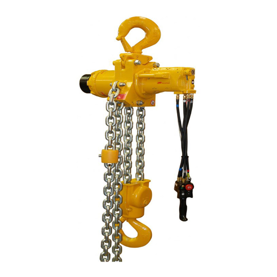
- Page 1 Product Maintenance Information Second Generation Liftchain Industrial Air Hoist Models LC2A015S, LC2A030D, LC2A040S, LC2A060S, LC2A060Q, LC2A080D, LC2A120D, LC2A180T, LC2A250Q (Dwg. MHP2659) Save These Instructions Form MHD56279 Edition 4 January 2010 71439319 2010 Ingersoll-Rand Company ©...
-
Page 2: Periodic Inspection
Hoist Model if necessary. LC2A015S Table 3: Hook Throat Normal and Discarded Width 8 x 24 4.72 LC2A030D Throat Width Discard Width Hoist Capacity LC2A040S 13 x 36 7.09 Model metric tons LC2A060S 16 x 45 8.85 8.90 LC2A015S 1.26 1.45... -
Page 3: Periodic Maintenance
PERIODIC MAINTENANCE Table 5: Maintenance Interval Chart Normal Application The following work can be completed by owner maintenance personnel System Air Filter Inspect system air filter every 45 days or 125 hours. Grease Fittings Lubricate grease fittings every 180 days or 500 hours. Gearbox Oil Level Check oil level in gearbox every 180 days or 500 hours. -
Page 4: Inspection Report
INSPECTION REPORT Ingersoll Rand Liftchain Industrial Air Hoist Model Number: Date: Serial Number: Inspected by: Reason for Inspection: (Check Applicable Box) 1. Scheduled Periodic Inspection ( ___ Quarterly ___ Semiannually ___ Yearly) 2. Discrepancy(s) noted during Frequent Inspection Operating Environment: Normal ___ Heavy ___ Severe ___ 3. -
Page 5: Troubleshooting
TROUBLESHOOTING This section provides basic troubleshooting information. Determination of specific causes to problems are best identified by thorough inspections performed by Ingersoll Rand trained technicians. The chart below provides a brief guide to common hoist and trolley symptoms, probable causes and remedies. SYMPTOM CAUSE REMEDY... -
Page 6: Maintenance
MAINTENANCE WARNING • Never perform maintenance on the hoist while it is supporting a load. • Before performing maintenance, tag controls: 0.047 inch minimum (1.2 mm minimum) WARNING - DO NOT OPERATE EQUIPMENT BEING REPAIRED. • Only allow Ingersoll Rand trained technicians to perform maintenance. •... - Page 7 Table 6: ‘C‘ Link Dimension Chain Size ‘A‘ Dimension Hoist Model LC2A015S 8 x 24 LC2A030D LC2A040S 13 x 36 LC2A060S 16 x 45 LC2A060Q 8 x 24 LC2A080D 13 x 36 LC2A120D LC2A180T 16 x 45 Securing LC2A250Q Screw...
- Page 8 Triple Fall Hoist (18 ton) Chain Reeving Single Fall Anchor Chain Bottom Block (Dwg. MHP2664) Double Fall (Dwg. MHP3044) NOTICE • Triple fall drawing MHP3044 is for reeving illustration only. May not resemble actual hoist. Anchor Refer to Dwg. MHP3044 on page 8. Chain Bottom Block To feed load chain through bottom hook assembly:...
-
Page 9: Hoist Disassembly
3. Do not heat a part with a flame to free it for removal, unless the part being heated Quad Fall Hoist (6 and 25 ton) is already worn or damaged beyond repair and no additional damage will occur to other parts. In general, the hoist is designed to permit easy disassembly and assembly. - Page 10 1. Motor, disc brake assembly and retainer ring (10) must be removed from pinion NOTICE shaft (25) before reduction gear assembly can be removed from hoist body. 2. Remove fill plug (1) from reduction gear end cover (5) and drain oil from reduction •...
-
Page 11: Cleaning, Inspection And Repair
14. Remove planet support assembly (341) from ring gear (19). 3 ton Double Fall 15. Remove bearing (18) from planetary carrier (17). Refer to Dwg. MHP2657. 16. Tap out planet axles (16) and remove planet gears (13), bearing rings (14), needle 1. -
Page 12: Hoist Assembly
8. With pinion shaft (25) still in place, install planet support assembly in ring gear Repair (19) carefully remove pinion shaft without removing planet support assembly and place ring gear flat on surface with planet support assembly facing up. Actual repairs are limited to the removal of small burrs and other minor surface 9. - Page 13 4 ton Single Fall and 8 ton Double Fall NOTICE Aligned Teeth Timing Mark • Ensure location of “V” shape on plate stop (96) is installed in the up position. Refer to Dwg. MHP3089 on page 13, A. Capscrew; B. Adapter Support;...
-
Page 14: Motor Assembly
21. Apply small amount of Loctite® “Instajoint 574” or equivalent on entire surface 4. Install plunger assembly on base plate and ensure plunger slides easily in the of flat ring (89), smooth out on entire surface, press flat ring (89) on reducer bore of the base plate. - Page 15 21. Turn the gears with splined hub and a tool. Check bearings do not rotate on bonded diameters and gears rotate freely. 22. Install motor cover (83) on motor cover (222). Install capscrews (90) with Use a continuous thin Loctite® 243 or equivalent. Refer to “TORQUE CHART” on page 19 for torque film of Loctite 603 or ®...
-
Page 16: Bottom Hook Assembly
10. Install attachment (right) (523) and (left) (524) to pendant handle (514) and NOTICE secure with washers (526) and capscrews (525) and (527). Install shorter capscrews in back, longer capscrews in front. 11. Facing pendant handle operation side, place levers (522) such that lever direction •... -
Page 17: Service Notes
SERVICE NOTES Form MHD56279 Edition 4... - Page 18 SERVICE NOTES Form MHD56279 Edition 4...
-
Page 19: Torque Chart
TORQUE CHART Standard Coarse Thread Torque SAE Grade 5 SAE Grade 8 Size Lubricated PTFE Lubricated PTFE 1/4-20 8-10 12-14 9-10 5/16-18 17-20 13-15 25-28 18-21 11-13 3/8-16 31-35 23-26 14-16 44-49 33-37 20-22 7/16-14 49-56 37-42 22-25 70-79 52-59 31-36 1/2-13 75-85... - Page 20 www.ingersollrandproducts.com...
Need help?
Do you have a question about the LC2A040S and is the answer not in the manual?
Questions and answers