
Subscribe to Our Youtube Channel
Related Manuals for Ingersoll-Rand LC2A060S


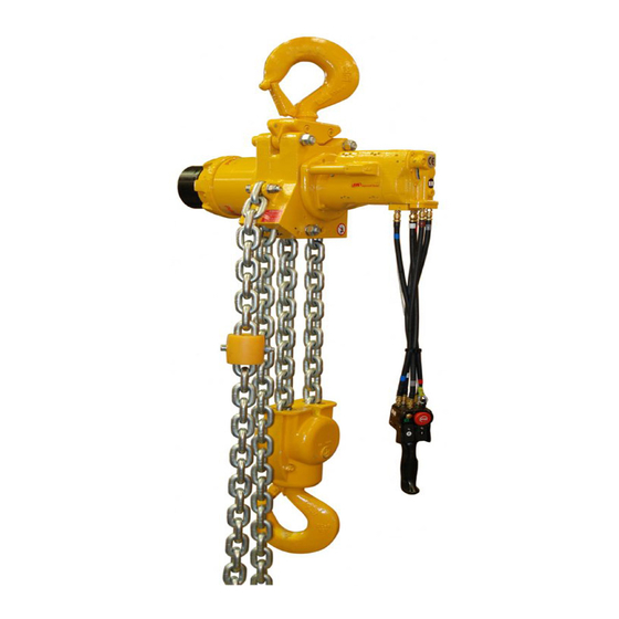
Summary of Contents for Ingersoll-Rand LC2A060S
- Page 1 Product Maintenance Information LOW HEADROOM AIR CHAIN HOIST Models LC2A060S, LC2A120D, LC2A180T and LC2A250Q Save These Instructions Form MHD56473 Edition 2 October 2013 45926011 2013 Ingersoll-Rand ©...
-
Page 2: Periodic Inspection
Replace worn or damaged parts. Clean, lubricate and Hoist Model reassemble. 3. Hooks. Inspect hooks carefully for cracks using magnetic particle or other LC2A060S suitable non-destructive method. Inspect hook retaining parts. Tighten or repair LC2A120D if necessary. -
Page 3: Periodic Maintenance
PERIODIC MAINTENANCE Table 5: Maintenance Interval Chart Normal Application The following work can be completed by owner maintenance personnel System Air Filter Inspect system air filter every 45 days or 125 hours. Grease Fittings Lubricate grease fittings every 180 days or 500 hours. Gearbox Oil Level Check oil level in gearbox every 180 days or 500 hours. -
Page 4: Inspection Report
INSPECTION REPORT Ingersoll Rand Liftchain Industrial Air Hoist Model Number: Date: Serial Number: Inspected by: Reason for Inspection: (Check Applicable Box) 1. Scheduled Periodic Inspection ( ___ Quarterly ___ Semiannually ___ Yearly) Operating Environment: 2. Discrepancy(s) noted during Frequent Inspection 3. -
Page 5: Troubleshooting
TROUBLESHOOTING This section provides basic troubleshooting information. Determination of specific causes to problems are best identified by thorough inspections performed by Ingersoll Rand trained technicians. The chart below provides a brief guide to common hoist and trolley symptoms, probable causes and remedies. SYMPTOM CAUSE REMEDY... -
Page 6: Maintenance
MAINTENANCE WARNING 0.047 inch minimum • Never perform maintenance on the hoist while it is supporting a load. (1.2 mm minimum) • Before performing maintenance, tag controls: WARNING - DO NOT OPERATE EQUIPMENT BEING REPAIRED. • Only allow Ingersoll Rand trained technicians to perform maintenance. •... - Page 7 3. Tighten securing screw. 4. Check hoist operation at rated load. If necessary repeat adjustment. (Dwg. MHP0472) NOTICE LC2A060S Load Chain Installation Follow instructions 1 to 5 under ‘Removing Load Chain’ on page 7. Also: 1. Remove hook assembly. •...
- Page 8 LC2A120D Load Chain Installation Follow instructions 1 to 5 under ‘Removing Load Chain’ on page 7. Also: 1. Remove capscrew (339) and lockwasher (303) from support (330). 2. Install the ‘C’ Link in the last link of the load chain that was attached to the support.
- Page 9 6. Unscrew muffler assembly (88) from reduction gear end cover (5) and remove Determining Twisted, Kinked or ‘Capsized‘ Load Chain ‘O’ ring (64). Contact factory if muffler assembly requires service. 7. Remove primary gear assembly (126) and sun gear (152). Ensure chain is not twisted, kinked or ‘capsized‘...
- Page 10 2. Remove cover plate (92). Powerhead Disassembly NOTICE Refer to Dwg. MHP3165. 1. Ensure reduction gear, disc brake and motor assemblies have been removed. • It is not necessary to remove overload valve (77) unless replacing ball (47) 2. Remove chain limit stop washer (110) from chain. Remove load chain from hoist and ‘O’...
-
Page 11: Cleaning, Inspection And Repair
6. Remove bearing (130). NOTICE 7. Drive pins (662) completely into planet pins (657) then tap planet pins out of planet support (655). • Refer to Dwg. MHP2644 on page 12 for instructions on Loctite placement, 8. Remove planet gears (661), thrust bearings (659) and washers (658). follow these instructions for all bearings on each gear. - Page 12 Hoist Disc Brake Assembly Refer to Dwgs. MHP2999 and MHP3038. 1. Lubricate and install ‘O’ ring (6) on brake housing (61). 2. Lubricate and install ‘O’ rings (64) and (6) on piston (63). Press piston assembly in brake housing (61). Internal ‘O’ ring (64) must enter brake housing first. Avoid damaging ‘O’...
- Page 13 2. Install oil seal (20) in hoist body (36) with lip of seal towards sprocket. 15. Apply Loctite® 574 Instajoint or equivalent on mating surfaces between cover 3. Install bearing (8) on sprocket (30) on shaft external gear teeth end. plate (92) and motor cover (83).
- Page 14 16. Install piston (692) in brake housing (689). Ensure ‘O’ ring in bore of piston is 3. Install plates in brake housing (61) in the following order: Friction plate without located toward brake housing. Refer to Dwg. MHP1627 on page 14, A. ‘O’ ring. clips (66) then drive plate (67) then friction plate with clips (72) then drive plate (67).
- Page 15 9. Lubricate and install ‘O’ rings (528) in recesses on sides of pendant handle (514). 10. Install attachment (right) (523) and (left) (524) to pendant handle (514) and secure with washers (526) and capscrews (525) and (527). Install shorter capscrews in back, longer capscrews in front. 11.
-
Page 16: Service Notes
SERVICE NOTES Form MHD56473 Edition 2... - Page 17 SERVICE NOTES Form MHD56473 Edition 2...
- Page 18 SERVICE NOTES Form MHD56473 Edition 2...
-
Page 19: Torque Chart
TORQUE CHART Standard Coarse Thread Torque SAE Grade 5 SAE Grade 8 Size Lubricated PTFE Lubricated PTFE 1/4-20 8-10 12-14 9-10 5/16-18 17-20 13-15 25-28 18-21 11-13 3/8-16 31-35 23-26 14-16 44-49 33-37 20-22 7/16-14 49-56 37-42 22-25 70-79 52-59 31-36 1/2-13 75-85... - Page 20 www.ingersollrandproducts.com...
Need help?
Do you have a question about the LC2A060S and is the answer not in the manual?
Questions and answers