Table of Contents
Advertisement
Quick Links
Advertisement
Table of Contents

Subscribe to Our Youtube Channel
Related Manuals for LOGICDATA COSMO Austin


Summary of Contents for LOGICDATA COSMO Austin
- Page 1 ADJUSTABLE BED FRAME OWNER’S MANUAL Document Version 6 | July 2021...
-
Page 2: Table Of Contents
No part of this manual may be reproduced mechanically, electronically, or by other means, in any form, without prior written permission of LOGICDATA Electronic & Software Entwicklungs GmbH. Violations involving copyright may result in legal action. -
Page 3: Safety
1. SAFETY IMPORTANT SAFETY INSTRUCTIONS This Owner’s Manual was designed according to the UL 962 Standard for Household and Commercial Furnishing. It contains safety instructions. All users must read the Owner’s Manual. All users have a responsibility to observe the safety instructions. Important accident prevention advice is found in this chapter. - Page 4 Usage outside of the intended use described in this Owner’s Manual is only allowed with writ-ten consent by LOGICDATA. Improper operation or usage outside of the intended use can re-sult in personal injury and damage to the system. Liability and warranty claims are void in cases of usage outside of the intended use.
- Page 5 EXPLANATION OF SYMBOLS AND SIGNAL WORDS DANGER The signal word DANGER indicates a hazardous situation which, if not avoided, will result in death or serious injury. WARNING The signal word WARNING indicates a hazardous situation which, if not avoided, could result in death or serious injury.
- Page 6 RESIDUAL RISKS Residual risks are the risks that remain after all relevant safety standards have been complied with. These have been evaluated through a thorough risk assessment. Read all instructions be- fore assembling and operating the Bed Frame. DANGER To reduce the risk of electric shock: •...
- Page 7 WARNING Review the instructions to ensure the appropriate critical components and accessories are being iused with the furnishing. WARNING Moderate risk of death or serious injury cal or mechanical components on the Bed Frame may lead to death or serious injury. •...
-
Page 8: Introduction
LIABILITY The descriptions of product characteristics in this Owner’s Manual are not a guarantee of the presence of these characteristics. LOGICDATA is not liable for damage or injury caused by: Improper product use Disregard of the documentation Unauthorized product alterations... - Page 9 FCC STATEMENT The Radio Frequency for this product is 2.4 GHz FCC COMPLIANCE The Adjustable Bed Frame complies with FCC CFR 47 Part 15 Subpart B/C. Operation is sub- ject to the following conditions: 1. The product may not cause harmful interference 2.
-
Page 10: Box Contents
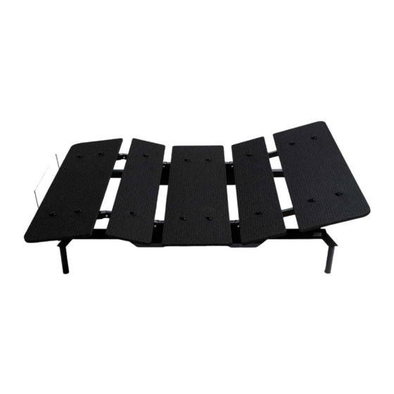
3. BOX CONTENTS The Adjustable Bed Frame is delivered in two boxes. The boxes contain all the parts and tools necessary to fully assemble and operate the system. Upon opening the packaging, use this check- list to ensure all the parts are present and in perfect condition. If any part is damaged or missing, SIDE RAIL (RIGHT) SIDE RAIL (LEFT) 2x CROSSBAR... - Page 11 HEAD PLATFORM REMOTE CONTROL HEAD INNER PLATFORM INNER 2x AAA BATTERIES BASE PLATFORM BASE QUICK START GUIDE INNER PLATFORM OWNER'S MANUAL INNER FOOT PLATFORM FOOT 16X PLATFORM SCREW RETAINER BAR ADJUSTABLE BED FRAME - OWNER’S MANUAL //...
-
Page 12: Assembly
4. ASSEMBLY TOOLS AND EQUIPMENT The Adjustable Bed Frame should be assembled by two adults. If you assemble the Bed Frame alone, be careful when lifting heavy parts. Ensure the assembly area is larger than the Bed Frame. Follow the steps carefully to assemble the Bed Frame correctly. UNPACKAGING Carefully open the packaging and check its contents, as described in Chapter 3, “Box Contents”. - Page 13 STEP 1: PREPARING THE OUTER FRAME Lay the Crossbars (D) and Side Rails (A, DO NOT REMOVE PROTECTIVE MATERIAL B) on the ground, as shown in the picture. DO NOT REMOVE STRAPPING TAPE IMPORTANT: • Ensure the Crossbars are parallel and roughly 5 feet (150 cm) apart.
- Page 14 STEP 3: CONNECTING THE BARS CAUTION Risk of minor or moderate injury through crushing The Side Rails are not secured while they are standing alone. If they fall over, this may lead to minor or moderate injury through crushing. • Do not attempt to stand the Side Rails upright before they are connected to the Crossbars •...
- Page 15 CAUTION Risk of minor or moderate injury through crushing • Connect the Crossbars (D) to the Side Rail (Left) (B) as shown in steps 1-3. CAUTION Risk of minor or moderate injury through crushing While screwing in the Crossbar Knobs, you will need to lift the moving parts of the Side Rails. Allowing these parts to fall may lead to minor or moderate injury through crushing.
- Page 16 STEP 5: MOUNTING THE BASE PLATFORM CAUTION Risk of minor or moderate injury through tripping While mounting the Platforms, you may have to step over the Power Cable. Tripping over the Cable may lead to injury. • Be careful not to trip over the Cable Lay the Base Platform (H) upside down across the Bed Frame.
- Page 17 STEP 6: MOUNTING THE OTHER PLATFORMS USE LABELS ON SIDE RAILS AND PLATFORMS Use 4 Platform Screws (N) to attach the nar- rower, Inner Platforms (G, L) to the Side Rails on either side of the Base Platform. Lay the Head and Foot Platforms (F, M) in po- sition on the Side Rails.
- Page 18 STEP 8: CONNECTING THE POWER CABLE Connect the Power Cable from the Control Box to the cable of the Power Converter (J). Connect the second Power Ca- ble to the Power Converter, then to the mains. Lay the Power Cable along the wall behind the Bed Frame to minimize the risk of tripping.
- Page 19 STEP 9: INSERTING THE BATTERIES Insert two 1,5V AAA batteries into the Re- mote Control and slide the cover into posi- tion. The batteries are provided for you. NOTICE Replace the batteries in the Remote Control once a year. Do not use rechargeable batteries. ADJUSTABLE BED FRAME - OWNER’S MANUAL //...
-
Page 20: Operation
5. OPERATION REMOTE CONTROL Each Adjustable Bed Frame is supplied with a Remote Control. Your Remote Control allows you to operate the Bed Frame from a distance of 16 feet (5 m). The Remote Control supplied with your product depends on the model you have ordered. Your Remote Control may include the following: Head Platform and Foot Platform UP/DOWN Buttons Move the Head and Foot Platforms up and down. - Page 21 PAIRING THE REMOTE CONTROL You must pair the Bed Frame to a Remote Control before operation. Ensure the Bed Frame has been unplugged for at least 10 seconds, then proceed as follows: 1. Plug the Bed Frame into the mains. This will automatically switch it to Pairing Mode for 30 minutes.
- Page 22 FACTORY RESET sitions you have stored will be deleted and replaced with the pre-set memory positions. To per- form a Factory Reset: 1. Press and hold the Foot DOWN and Head DOWN buttons for 10 seconds. 2. When the reset is complete, the Control Box will click twice. 3.
- Page 23 PERFORMING A FLAT POSITION RESET To perform a Flat Position Reset: 1. Press the Sleeping Position Button for at least 10 seconds. theinput. 3. Perfom a Reference Drive with the Sleeping Position Button or any UP/ DOWN Button (see section "Reference Drive"). SYNC MODE IMPORTANT Sync Mode allows you to control two Bed Frames with one Remote Control.
-
Page 24: Disassembly And Transportation
6. DISASSEMBLY AND TRANSPORTATION DISASSEMBLY mains. Then, follow the assembly instructions in reverse order. To minimize the risk of pinching when transporting the Side Rails, secure all moving parts with packaging tape. TRANSPORTATION After it has been fully assembled, the Bed Frame should only be moved short distances within the same room. -
Page 25: Cleaning And Maintenance
7. CLEANING AND MAINTENANCE CLEANING To clean the Adjustable Bed Frame, use a dry or slightly damp lint-free cloth to wipe the Bed Frame. WARNING Moderate risk of death or serious injury through electric shocks Leaving the Bed Frame plugged in while cleaning it may lead to death or serious injury through electric shocks. -
Page 26: Troubleshooting
8. TROUBLESHOOTING BEHAVIOR POSSIBLE CAUSE / SOLUTION The Bed Frame does not 1. The Bed Frame is not connected properly. Check the power respond when Buttons are connection pressed. 2. Time-out has been reached due to continuous operation. Do not operate the Bed Frame for at least 6 minutes. This will re- set the time-out. - Page 27 NOTICE When an Emergency Lowering is performed, only the Bed Frame connected to the Battery Strap will be operated. You will need to perform separate Emergency Lowerings for Bed Frames con- nected by the Sync Cable. Parts of the Bed Frame do not Make sure no persons or heavy objects are on the Bed move evenly.
-
Page 28: Technical Data
NOTICE The permitted maximum load is dependent on input voltage. At the lower end of the input volt- age range, maximum load may be reduced. Contact LOGICDATA for further details. 10. FINAL DISPOSAL Before disposing of the product, check the types of raw materials used in the Bed Frame and make plans to dispose of them accordingly.
Need help?
Do you have a question about the COSMO Austin and is the answer not in the manual?
Questions and answers