Advertisement
Quick Links
ISL28023EVAL1Z, ISL28023EVAL2Z
ISL28023 Precision Digital Power Monitor Evaluation Kit
Introduction
The Precision Digital Power Monitor (DPM) Evaluation Kit is a
three evaluation board design that demonstrates the
functionality of the ISL28023. The ISL28023 is an IC with a
16-bit Analog-to-Digital Converter (ADC), an 8-bit
Digital-to-Analog Converter (DAC), and analog comparators
that monitors for undervoltage, overvoltage and overcurrent
conditions. The IC is serially controlled through an I
device abides by the PMBus standards.
The DPM Evaluation Kit is accompanied by a graphical user
interface (GUI) that allows the user to configure ISL28023 for
monitoring bus voltage and current in a specific application.
The GUI has a data save feature allowing the transfer of
measurement data to other software application for analysis.
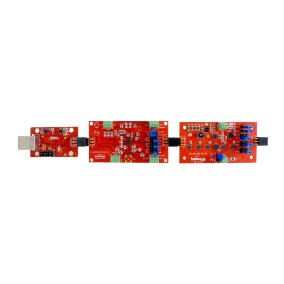
The ISL28023 DPM Evaluation Kit consists of three boards; a
USB dongle, a generic ISL28023EVAL1Z board and an
ISL28023EVAL2Z demonstration board.
Dongle Evaluation Board
(ISLUSBPWRDONGLE1Z)
The dongle board mates from a PC to the ISL28023 via a
microcontroller. The microcontroller converts USB commands
2
sourced from the PC to an I
C header. The I
SDA) are connected to the right angle header at the edge of
the board. The dongle board has a circuit that converts the USB
supply voltage to 3.3V. The 3.3V supply circuit has an
ISL28022 connected to monitor the current sourced by the
supply. Each circuit has been optimized to measure 100mA at
full scale. The 3.3V supply output and the SDA and SCL lines of
2
C bus are routed to the right angle connector.
the I
USB DONGLE
AN1932 Rev 3.00
February 1, 2016
2
C bus. The
2
C pins (SCL and
ISL28023EVAL1Z
GENERIC EVAL BOARD
FIGURE 1. ISL28023 EVALUATION KIT EVALUATION BOARDS
USER'S MANUAL
ISL28023 Generic Board (ISL28023EVAL1Z)
The generic ISL28023 board is a nonconfigured ISL28023 that
connects the analog inputs to the outside world. The board
allows a user to build a system that requires voltage, current or
power monitoring around the ISL28023. The analog inputs
(VINP, VINM and VBUS) of the ISL28023 accept input voltages
ranging from 0V to 60V. The ISL28023 allows the user to
uniquely configure the slave address via jumper selections.
The ISL28023 can be powered from a user defined source or
the 3.3V supply generated from the USB voltage. The
acceptable power supply voltage range for the ISL28023 is
from 3V to 5.5V. The external clock/interrupt pin is routed to
the outside world via a jumper selection. The maximum
measurable input differential (VINP - VINM) is ±80mV. The
differential voltage between the VINP and VINM pins can
withstand a magnitude of 60V. The differential supply
tolerance allows for the debugging of catastrophic circuit
events.
ISL28023 Demo Board (ISL28023EVAL2Z)
A peripheral circuit is required to demonstrate the functionality
of the ISL28023. The ISL28023 is paired up with a buck
regulator (ISL85415) and some sample loads to measure the
current and efficiency calculations of the regulator to the load.
The buck circuit allows the user to define a unique load that
connects to the regulator. The user can define the switching
frequency of the regulator by programming a resistor value
into the ISL23345 digital potentiometer. All features of the
ISL28023 are available.
Ordering Information
PART NUMBER
ISL28023EVAL1Z
Evaluation Board
ISL28023EVKIT1Z
Evaluation Kit
ISL28023EVAL2Z
GENERIC EVAL BOARD
AN1932
Rev 3.00
February 1, 2016
DESCRIPTION
Page 1 of 20
Advertisement

Related Manuals for Renesas ISL28023EVAL1Z


Summary of Contents for Renesas ISL28023EVAL1Z
- Page 1 60V. The differential supply The ISL28023 DPM Evaluation Kit consists of three boards; a tolerance allows for the debugging of catastrophic circuit USB dongle, a generic ISL28023EVAL1Z board and an events. ISL28023EVAL2Z demonstration board. ISL28023 Demo Board (ISL28023EVAL2Z)
-
Page 2: System Requirements
- On the following screen, it will ask about how to install • ISL28023 Demo Board (ISL28023EVAL2Z) hardware. Select the recommended option (Installing from • ISL28023 Generic Board (ISL28023EVAL1Z) CD) and follow the directions • USB to I C Dongle Board (ISLUSBPWRDONGLE1Z) - The USB is the only connector needed •... - Page 3 ISL28023EVAL1Z, ISL28023EVAL2Z FIGURE 3. MAIN WINDOW OF THE ISL28023 GENERIC USER INTERFACE (GUI) CONNECTED TO THE ISL28023 GENERIC BOARD DPM MEASUREMENT FUNCTIONALITY LOOP DELAY Enabling the current functional block on the DPM interface The loop delay field in the lower right corner of the GUI allows the requires the user to enter a shunt resistor value.
- Page 4 ISL28023EVAL1Z, ISL28023EVAL2Z FIGURE 6. The SMB ALERT CONFIGURATION WINDOW The outputs of the threshold comparators feed into the SMB Alert FIGURE 5. THE WINDOW THAT CONTROLS THE ISL28023 control window. The comparator output can be routed to the COMPARATORS SMBALERT pins of the device via checking the respective feed-through check box.
-
Page 5: External Temperature Sensor
ISL28023EVAL1Z, ISL28023EVAL2Z MARGIN DAC Choose the SMB Alert selection under the ISL28023 drop down menu. A window similar to Figure 7 appears. FIGURE 9. THE CURRENT PEAK DETECT WINDOW The current peak detect feature reports the min and max reading of a single sample. -
Page 6: System View
ISL28023EVAL1Z, ISL28023EVAL2Z CONNECTING MULTIPLE ISL28023 EVALUATION SYSTEM VIEW BOARDS TO A DONGLE When multiple ISL28023 devices are connected to the dongle board, a system view screen is available. The system view allows An ISL28023 design can have 55 devices connected on a single the user to view all the ISL28023 devices as configured. - Page 7 ISL28023EVAL1Z, ISL28023EVAL2Z BUTTON TO PRESS TO GO TO NEXT SITE FIGURE 12. ISL28023 SINGLE SITE VIEW ILLUSTRATES THE BUTTON TO GO TO THE NEXT DEVICE/SITE FIGURE 13. SYSTEM VIEW FOR THE ISL28023 SOFTWARE AN1932 Rev 3.00 Page 7 of 20...
-
Page 8: Saving Data
ISL28023EVAL1Z, ISL28023EVAL2Z USB SUPPLIES The ISL28023 Demo Software allows a user to build their own board to mate with the Dongle board. The final design of the third party board may use the dongle generated 3.3V power supply. The user can monitor the current draw from 3.3V supply by selecting USB Supplies under the dongle drop down menu. - Page 9 ISL28023EVAL1Z, ISL28023EVAL2Z Running the Software with the ISL28023 All the controls and features discussed in the ISL28023 generic board software are available to the user in the Demo software. Demo Board The ISL28023 Demo board connects the ISL28023 to a buck Connect and power the Demo board to the dongle board as regulator (ISL85415) and some resistive loads.
- Page 10 ISL28023EVAL1Z, ISL28023EVAL2Z Setting the Regulated Output Voltage Enabling Efficiency Readings Press the "Set Reg V" will launch the margin DAC window. The By measuring the power going into the ISL85415 regulator and margin DAC is connected to R or the R...
- Page 11 TITLE: ISL28023 Generic Design UPDATED BY: DATE: 3P3V SDA* SGND SCL* TESTER MASK# HRDWR ID REV. PLEASE PUT SILK LABEL NEXT TO CONNECTOR FILENAME: SHEET Th F b 06 14 43 40 2014 FIGURE 20. SCHEMATIC OF THE ISL28023EVAL1Z BOARD...
- Page 12 ISL28023EVAL1Z, ISL28023EVAL2Z ISL28023EVAL1Z Bill of Materials MANUFACTURER PART UNITS REFERENCE DESIGNATOR DESCRIPTION MANUFACTURER ISL28023EVAL1ZREVAPCB PWB-PCB, ISL28023EVAL1Z, REVA, ROHS IMAGINEERING INC C2012X7R2A104K C5, C6, C9, C10, C11, C12 CAP, SMD, 0805, 0.1µF, 100V, 10%, X7R, ROHS TDK ECJ-2VB1E104K C7, C8 CAP, SMD, 0805, 0.1µF, 25V,10%,X7R,ROHS...
- Page 13 FREQUENCY_SEL THIS IS THE OUTPUT FEMALE HEADER 3P3V SGND THIS IS THE INPUT MALE HEADER SALERT 0.1UF SALERT SGND VLOGIC SGND MSTR_EN 3P3V UNNAMED_3_ISL23345_I37_RH0 3P3V MSTR_EN VIN* INPUT UNNAMED_3_ISL23345_I37_RH1 UNNAMED_3_ISL23345_I37_RH2 AGND AGND INPUT AGND AGND UNNAMED_3_ISL23345_I37_RL1 SGND SGND 0.020 A0 A1 A2 SGND 0.1UF A1_D...
- Page 14 0.1UF 3P3V SGND 0.1UF SGND 3P3V 0.1UF 3P3V SGND UNNAMED_2_ISL83699_I27_NO1 COM1 0.5MA AGND 6.98K UNNAMED_2_ISL83699_I31_NO1 COM1 COM2 10MA AGND 50MA IN12 0.5MA 100MA COM2 300MA MSTR_EN NOT_WC UNNAMED_2_ISL83699_I27_NO3 500MA IN12 COM3 50MA AGND 3.48K UNNAMED_2_ISL83699_I31_NO3 A0_D COM3 COM4 A1_D 3P3V AGND IN34 0.1UF...
- Page 15 ISL28023EVAL1Z, ISL28023EVAL2Z ISL28023EVAL2Z Bill of Materials REFERENCE MANUFACTURER PART UNITS DESIGNATOR DESCRIPTION MANUFACTURER ISL28023EVAL2ZREVAPCB PWB-PCB, ISL28023EVAL2Z, REVA, ROHS IMAGINEERING INC GRM36X7R333K016AQ CAP, SMD, 0402, 33000pF, 16V, 10%, X7R, MURATA ROHS ECJ-0EB1H471K CAP, SMD, 0402, 470pF, 50V, 10%, X7R, PANASONIC ROHS...
- Page 16 ISL28023EVAL1Z, ISL28023EVAL2Z ISL28023EVAL2Z Bill of Materials (Continued) REFERENCE MANUFACTURER PART UNITS DESIGNATOR DESCRIPTION MANUFACTURER CRCW1206-000Z RES, SMD, 1206, 0Ω, 1/4W, TF, ROHS VISHAY RES, SMD,1206, 49.9Ω, 1/4W, 1%, TF, ROHS CRCW251215R0FKEG R1, R2 RES, SMD, 2512, 15Ω, 1W, 1%, TF, ROHS...
- Page 17 3P3V UNNAMED_3_SMLED_I234_A POL_PG 3P3V_PG POL_SEL0 POL_SEL1 UNNAMED_3_C8051F320_I232_P06 POL_SEL[0..2] MSTR_EN P0.1 P1.2 POL_SEL2 MOUNT P0.0 P1.3 EN_3P3V P1.4 MSTR_EN 3P3V UNNAMED_3_SMRES_I230_A UNNAMED_3_C8051F320_I232_DP P1.5 C8051F320 UNIVERSAL6 UNNAMED_3_SMRES_I231_A UNNAMED_3_C8051F320_I232_DN P1.6 MCU_PWR P1.7 P2.0 USB_PWR REGIN MOUNT P2.1 VBUS PLACE AT RIGHT EDGE OF BOARD. 0.1UF RIGHT ANGLE FEMALE CONNECTOR UNNAMED_3_C8051F320_I232_RSTC2CK...
- Page 18 3.3V CURRENT LIMIT IS 100MA 5V TO 3.3V REG 3.3V CURRENT LIMIT IS 100mA 5V TO 3.3V REG 3P3V USB_PWR 0.1UF ISL80101-3.3 VBUS isl28022_QFN UNNAMED_2_ISL28022QFN_I220_VINP VINP VOUT VINN VOUT EXT_CLK/INT SENSE/ADJ ENABLE 100K SMBCLK/SCL ISL80101IRAJZ SMBDAT/SDA SLAVE ADDR = OX9E/F 3P3V_PG FIGURE 24.
- Page 19 ISL28023EVAL1Z, ISL28023EVAL2Z ISLUSBPWRDONGLE1Z Bill of Materials MANUFACTURER PART NUMBER UNITS REFERENCE DESIGNATOR DESCRIPTION MANUFACTURER C2012X7R1E105K C1, C8, C10, C20, C22 CAP, SMD, 0805, 1.0µF, 25V, 10%, X7R, ROHS ECJ-2VB1E104K C2, C6, C21 CAP, SMD, 0805, 0.1µF, 25V, 10%, PANASONIC X7R, ROHS...
- Page 20 10. It is the responsibility of the buyer or distributor of Renesas Electronics products, or any other party who distributes, disposes of, or otherwise sells or transfers the product to a third party, to notify such third party in advance of the contents and conditions set forth in this document.
- Page 21 Mouser Electronics Authorized Distributor Click to View Pricing, Inventory, Delivery & Lifecycle Information: Renesas Electronics ISL28023EVKIT1Z...
Need help?
Do you have a question about the ISL28023EVAL1Z and is the answer not in the manual?
Questions and answers