Table of Contents
Advertisement
Quick Links
ISL81801DEMO1Z
Demonstration Board
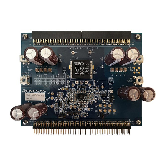
The ISL81801DEMO1Z demonstration board (shown in
synchronous buck-boost controller that provides external soft-start, independent enable functions, and integrates
UV/OV/OC/OT protection. Programmable switching frequency ranging from 100kHz to 600kHz helps to optimize
the inductor size while the strong gate driver delivers up to 20A for the buck-boost output.
Key Features
• Wide input range: 32V to 80V
• Bidirectional operation
• High light-load efficiency in pulse skipping DEM operation
• Programmable soft-start
• Optional DEM/PWM operation
• Optional CC/HICCUP OCP protection
• Supports prebias output with soft-start
• PGOOD indicator
• OVP, OTP, and UVP protection
• Parallelable operation
Specifications
The ISL81801DEMO1Z demonstration board is designed for high current applications. The current rating of the
ISL81801DEMO1Z is limited by the FETs and inductor selected. The ISL81801DEMO1Z electrical ratings are
shown in
Table
1.
Table 1.
Electrical Ratings
Parameter
Input Voltage
Switching Frequency
Output Voltage
Output Current
OCP Set Point
Ordering Information
Part Number
ISL81801DEMO1Z
Related Literature
For a full list of related documents, visit our website:
•
ISL81801
product page
R16UH0005EU0100 Rev.1.00
Oct.16.20
Figure
32V to 80V
200kHz
48V
10A
Minimum 11A at ambient room temperature
Parallelable high voltage buck-boost controller demonstration board
8) features the ISL81801, a 80V high voltage
Rating
Description
User Manual
Page 1 of 18
Advertisement
Table of Contents

Related Manuals for Renesas ISL81801DEMO1Z


Summary of Contents for Renesas ISL81801DEMO1Z
- Page 1 • OVP, OTP, and UVP protection • Parallelable operation Specifications The ISL81801DEMO1Z demonstration board is designed for high current applications. The current rating of the ISL81801DEMO1Z is limited by the FETs and inductor selected. The ISL81801DEMO1Z electrical ratings are shown in Table Table 1.
- Page 2 CurrentSharing Figure 1. ISL81801DEMO1Z Block Diagram...
-
Page 3: Functional Description
ISL81801DEMO1Z 1. Functional Description Functional Description The ISL81801DEMO1Z demonstrates the performance of the ISL81801 TQFN IC. The board provides an easy and complete demonstration of all the IC and board functions. As shown in Figure 7, 32V to 80V V... - Page 4 ISL81801DEMO1Z 1. Functional Description Table 2. Set Phase Shift for Interleaving CLK Lag RT by (°) VC5 (1) VC5 (1) (Active) (Active) IIN_B Open Shorted Open Shorted (Active) (Active) Total Load (A) Figure 4. Current Sharing Among Three Units Bidirectional Operation Figure 5 for proper setup.
- Page 5 ISL81801DEMO1Z 1. Functional Description Table 3. Operating Options Jumper Position Function EN-GND Disable output EN Floating Enable output Floating Enable input current limit -VCC5 Disable input current limit FBI-GND Disable V limit FBI Floating Enable V limit Pin 1-2 Pin 2-3...
-
Page 6: Pcb Layout Guidelines
MOSFETs. 2. If signal components and the IC are placed separately from the power train, Renesas recommends using full ground planes in the internal layers with shared SGND and PGND to simplify the layout design. Otherwise, use separate ground planes for the power ground and the small signal ground. - Page 7 12. Use a pair of traces with minimum loop for the input or output current sensing connection. 13. Ensure the feedback connection to the output capacitor is short and direct. ISL81801DEMO1Z Demonstration Board Figure 8. ISL81801DEMO1Z Demonstration Board (Top) Figure 9. ISL81801DEMO1Z Demonstration Board (Bottom) R16UH0005EU0100 Rev.1.00 Page 7 of 18 Oct.16.20...
- Page 8 ISL81801DEMO1Z Circuit Schematic Jumpers Default J8: "CCM" caped J3: OPEN J7:"GND" caped J6: OPEN J9: "CC" caped Figure 10. Schematic...
-
Page 9: Bill Of Materials
ISL81801DEMO1Z 2. PCB Layout Guidelines Bill of Materials Reference Designator Description Manufacturer Manufacturer Part C31, C32 CAP, SMD, 0805, 10µF, 16V, 10%, X7S Murata GRM21BC71C106KE11L C1, C5, C6, C8-C10, CAP, SMD, 1210, 10µF, 100V, 10%, X7S Murata GRM32EC72A106KE05L C19-C24, C52-C55... - Page 10 ISL81801DEMO1Z 2. PCB Layout Guidelines Reference Designator Description Manufacturer Manufacturer Part R46, R84, R85 RES, SMD, 0603, 20Ω, 1/10W, 1%, TF Panasonic ERJ-3EKF20R0V R11, R15, R16, R19, RES, SMD, 0603, 2.2Ω, 1/10W, 1%, TF Panasonic ERJ-3RQF2R2V R20, R22-R24, R27-R29 RES, SMD, 0603, 100Ω, 1/10W, 1%, TF...
-
Page 11: Board Layout
ISL81801DEMO1Z 2. PCB Layout Guidelines Board Layout Figure 11. Assembly Top Figure 12. Top Layer R16UH0005EU0100 Rev.1.00 Page 11 of 18 Oct.16.20... - Page 12 ISL81801DEMO1Z 2. PCB Layout Guidelines Figure 13. Layers 2 and 3 (Solid Ground), Identical Figure 14. Bottom Layer R16UH0005EU0100 Rev.1.00 Page 12 of 18 Oct.16.20...
- Page 13 ISL81801DEMO1Z 2. PCB Layout Guidelines Figure 15. Assembly Bottom R16UH0005EU0100 Rev.1.00 Page 13 of 18 Oct.16.20...
-
Page 14: Typical Performance Curves
ISL81801DEMO1Z 3. Typical Performance Curves Typical Performance Curves = 48V, R = 4.7k, unless otherwise noted. 36Vi -DEM 36Vi -CCM 48Vi -DEM 48Vi -CCM 80Vi -DEM 80Vi -CCM Load (%) Load (%) Figure 16. Efficiency, CCM Figure 17. Efficiency, DEM... - Page 15 ISL81801DEMO1Z 3. Typical Performance Curves = 48V, R = 4.7k, unless otherwise noted. (Continued) Figure 21. Input Port CV/CC Regulation (R = 8.45k) Figure 22. Output Port CV/CC Regulation (48V, 11A) 48.5 48.5 36Vi -CCM 36Vi -DEM 48Vi -CCM 48Vi -DEM 48.4...
- Page 16 ISL81801DEMO1Z 3. Typical Performance Curves = 48V, R = 4.7k, unless otherwise noted. (Continued) Phase 1 50V/Div 500mV/Div Phase 2 50V/Div 200mV/Div 2A/Div 10A/Div 10µs/Div 2ms/Div Figure 27. Phase 1, Phase 2, V and Inductor Current, Figure 28. Load Transient, V...
- Page 17 ISL81801DEMO1Z 3. Typical Performance Curves = 48V, R = 4.7k, unless otherwise noted. (Continued) Phase 1 50V/Div Phase 1 50V/Div Phase 2 50V/Div Phase 2 50V/Div 50V/Div 50V/Div 20A/Div 20A/Div 4ms/Div 100ms/Div Figure 33. Start-Up Waveform, V = 80V, I = 5A, CCM Figure 34.
-
Page 18: Revision History
ISL81801DEMO1Z 4. Revision History Revision History Rev. Date Description 1.00 Oct.16.20 Initial release R16UH0005EU0100 Rev.1.00 Page 18 of 18 Oct.16.20... - Page 19 Renesas' products are provided only subject to Renesas' Terms and Conditions of Sale or other applicable terms agreed to in writing. No use of any Renesas resources expands or otherwise alters any applicable warranties or warranty disclaimers for these products.
Need help?
Do you have a question about the ISL81801DEMO1Z and is the answer not in the manual?
Questions and answers