Table of Contents
Advertisement
Quick Links
ISL28022EVKIT1Z
ISL28022 Digital Power Monitor Evaluation Kit
Introduction
The
ISL28022
Digital Power Monitor (DPM) evaluation kit is a
three evaluation board design that demonstrates the
functionality of the ISL28022. By design, the ISL28022 is
considered a digital helper for a variety of applications ranging
from energy optimization to diagnostics of complex systems.
The three board evaluation kit demonstrates the functionality
of the DPM for three specific applications while offering a
configurable board for users to connect to their systems.
The DPM Evaluation kit is accompanied by a graphical user
interface (GUI) that allows the user to configure the ISL28022
for monitoring bus voltage and current in a specific
application. The GUI has a data save feature allowing the
transfer of measurement data to another software application
for analysis.
Dongle Evaluation Board
The ISL28022 DPM evaluation kit consists of three boards; a
dongle, a generic ISL28022 board, and a R
dongle board mates from a PC to the ISL28022 via a
microcontroller. The microcontroller converts USB commands
2
sourced from the PC to an I
C header. The I
are connected to the right angle header at the edge of the board.
The dongle board has three circuits that convert the USB supply
voltage from 5V to 3.3V, 12V and a selectable point of load (POL)
voltage. Each voltage translation circuit has a ISL28022
connected to monitor the current sourced by the supply. Each
circuit has been optimized to measure 100mA at full scale. The
three supply voltages are routed to the right angle connector
2
along with the I
C pins, SDA and SCL.
AN1875 Rev 3.00
February 17, 2016
(ISL28022USBEV1Z)
board. The
LOAD
2
C pins (SCL and SDA)
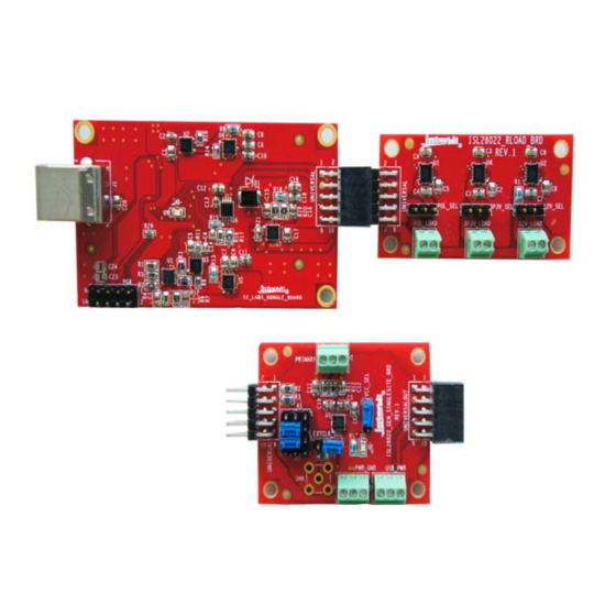
DONGLE BOARD
ISL28022 EVALUATION BOARD
FIGURE 1. ISL28022 EVALUATION KIT EVALUATION BOARDS
USER'S MANUAL
R
Board
(ISL28022DBEV1Z)
LOAD
nd
The 2
DPM evaluation kit board is the R
purpose of the R
board is to exercise the three supplies
LOAD
sourced by the dongle board. The R
user to source power to a user defined system via a jumper
selection. The R
board has a programmable load resistor.
LOAD
The programmable load resistor is a ISL23345 digitally
controlled potentiometer (DCP). The evaluation software
allows the user to configure the DCP for monitoring power. The
R
board connects to the dongle board to demonstrate the
LOAD
functionality of the ISL28022.
ISL28022 Generic Board
The final ISL28022 board is a non-configured ISL28022 that
connects the analog inputs to the outside world. The board
allows a user to build a system that requires either current or
power monitoring around the ISL28022. The analog inputs
(VINP, VINM and VBUS) of the ISL28022 accept input voltages
ranging from 0V to 60V. The ISL28022 allows the user to
uniquely configure the slave address via jumper selections.
The ISL28022 can be powered from a user defined source or
the 3.3V supply generated from the USB voltage. The
acceptable power supply voltage range for the ISL28022 is
from 3V to 5.5V. The external clock/interrupt pin is routed to
the outside world via a jumper selection. The maximum
measurable input differential ±(VINP - VINM) is ±300mV. The
differential voltage between the VINP and VINM pins can
withstand a magnitude of 60V. The differential supply
tolerance allows for the debug of catastrophic circuit events.
R
BOARD
LOAD
AN1875
Rev 3.00
February 17, 2016
board. The
LOAD
board also allows the
LOAD
(ISL28022MBEV1Z)
Page 1 of 15
Advertisement
Table of Contents

Related Manuals for Renesas ISL28022EVKIT1Z


Summary of Contents for Renesas ISL28022EVKIT1Z
- Page 1 USER’S MANUAL ISL28022EVKIT1Z AN1875 ISL28022 Digital Power Monitor Evaluation Kit Rev 3.00 February 17, 2016 Introduction Board (ISL28022DBEV1Z) LOAD The 2 DPM evaluation kit board is the R board. The ISL28022 Digital Power Monitor (DPM) evaluation kit is a LOAD...
-
Page 2: System Requirements
ISL28022EVKIT1Z Evaluation Package (Online Order) The ISL28022 Evaluation Kit (ISL28022EVKIT1Z) contains the following items: • Dongle Board (SI_Labs_Dongle_Board) - ISL28022USBEV1Z • Generic ISL28022 Board (ISL28022_GEN_SINGLESITE_BRD) - ISL28022MBEV1Z • R Board (ISL28022_RLOAD_BRD) - ISL28022DBEV1Z LOAD • Evaluation Software (Online) • User Guide •... - Page 3 ISL28022EVKIT1Z FIGURE 3. ISL28022 EVALUATION KIT SOFTWARE WINDOW BOARD LOAD DONGLE BOARD FIGURE 4. ISL28022 DEMONSTRATION SOFTWARE CONFIGURATION AN1875 Rev 3.00 Page 3 of 15 February 17, 2016...
- Page 4 ISL28022EVKIT1Z Demonstration Software dongle board, the evaluation software searches specific resistors to determine the type of board that is connected to • Connect the R board to the dongle as shown in Figure LOAD the dongle. The board that is connected determines the Enable communication between the evaluation board and the behavior of the software.
-
Page 5: Data Collecting
ISL28022EVKIT1Z • Mouse to the Demo drop down menu and select the R • Connect the ISL28022 board to the dongle as shown in LOAD selection. Two windows will appear. A USB supply monitor Figure 6. Enable communication between the evaluation window and a R window. - Page 6 ISL28022EVKIT1Z LOOP DELAY (S) • The Vbus thresholds can be set between 0V and 60V. Vshunt thresholds range between ±300mV. The Vbus and Vshunt • Timing between successive measurements can be fast thresholds do not scale versus BRNG and PGA settings. Once causing the LCD readout to be illegible.
- Page 7 ISL28022EVKIT1Z USB SUPPLIES - The ISL28022 Demo Software allows a user to build their own board to mate with the Dongle board. The final design of the third party board may use the dongle generated power supplies. The user can monitor the current draw for each of the Dongle supplies by selecting USB Supplies under the Dongle drop down menu.
-
Page 8: System View
ISL28022EVKIT1Z FIGURE 14. PICTURE OF MULTIPLE ISL28022 EVALUATION BOARDS CONNECTED TO THE DONGLE BOARD FIGURE 15. PICTURE OF THE MAIN GUI WITH AT LEAST ONE ISL28022 EVALUATION BOARD CONNECTED TO THE DONGLE BOARD • Configure the site as desired. The slave address in the upper... - Page 9 ISL28022EVKIT1Z FIGURE 16. PICTURE OF THE SYSTEM VIEW WINDOW FOR MULTIPLE ISL28022 CONNECTED TO THE DONGLE FIGURE 17. PAGE 1 SCHEMATIC OF THE ISL28022 DONGLE AN1875 Rev 3.00 Page 9 of 15 February 17, 2016...
- Page 10 ISL28022EVKIT1Z CONFIDENTIAL IN REVIEW FIGURE 18. PAGE 2 SCHEMATIC OF THE ISL28022 DONGLE AN1875 Rev 3.00 Page 10 of 15 February 17, 2016...
- Page 11 TABLE 1. ISL28022 DONGLE BOARD BILL OF MATERIAL REFERENCE ITEM# PART NAME PART VALUE FOOTPRINT DESIGNATOR VENDOR NAME VENDOR P/N MANUFACTURER NAME MANUFACTURER P/N USB Micro Controller C8051F320 - LQFP32 QUAD32 Digi-Key 336-1259-ND Silicon Labs C8051F320LQFP32 Linear Regulator ISL80101 - 3.3V DFN10 Digi-Key ISL80101IR33Z-T-ND Intersil Corp...
- Page 12 TABLE 1. ISL28022 DONGLE BOARD BILL OF MATERIAL (Continued) REFERENCE ITEM# PART NAME PART VALUE FOOTPRINT DESIGNATOR VENDOR NAME VENDOR P/N MANUFACTURER NAME MANUFACTURER P/N 10 pin Jumper 5x2 pin 0.1 spacing CON10 Universal Generic Generic Right angle Female Connector 10 pin Jumper 5x2 pin 0.1 spacing CON10...
- Page 13 ISL28022EVKIT1Z SALERT1 UNIVERSAL UNIVERSAL AUTOMATED LOAD OR UNIVERSAL UNIVERSAL GPIO1 3P3V UNIVERSAL UNIVERSAL UNIVERSAL UNIVERSAL EXTERNAL LOAD (12V CHANNEL) GPIO2 UNIVERSAL UNIVERSAL POL_VDD 12V_LOAD 12V_SEL USB_PWR 12V_SEL 12V_LOAD 12V_SEL PLACE AT LEFT EDGE OF BOARD. 0.1UF 3P3V RIGHT ANGLE MALE CONNECTOR 0.1UF...
- Page 14 ISL28022EVKIT1Z FIGURE 20. SCHEMATIC OF THE ISL28022 GENERIC BOARD TABLE 3. ISL28022 GENERIC BOARD BILL OF MATERIAL ITEM REFERENCE VENDOR PART NAME PART VALUE FOOTPRINT DESIGNATOR NAME VENDOR P/N NAME MFR P/N Capacitor 0.1µF 0805 Generic Generic Capacitor 1µF/100V 0805...
-
Page 15: Sales Offices
10. It is the responsibility of the buyer or distributor of Renesas Electronics products, or any other party who distributes, disposes of, or otherwise sells or transfers the product to a third party, to notify such third party in advance of the contents and conditions set forth in this document.
Need help?
Do you have a question about the ISL28022EVKIT1Z and is the answer not in the manual?
Questions and answers