Table of Contents
Advertisement
Quick Links
Advertisement
Table of Contents

Related Manuals for S.R.Smith multiLift 2


Summary of Contents for S.R.Smith multiLift 2
- Page 1 multiLift 2 POOL LIFT OWNER’S MANUAL & MAINTENANCE PROCEDURES S.R. SMITH, LLC CORPORATE HEADQUARTERS P.O. Box 400 • 1017 S.W. Berg Parkway Canby, Oregon 97013 USA Phone (503) 266 2231 • Fax (503) 266 4334 www.srsmith.com 700-9700 7.14.2022...
-
Page 2: Table Of Contents
TABLE OF CONTENTS DECK PROFILE SHEET CONFIRMATION .................. 3 INTRODUCTION ........................4 Using the multiLift™2 ......................4 WARNINGS AND SAFETY SUMMARY ..................5 PRODUCT OVERVIEW ......................6 COMPONENT DESCRIPTION ....................7 UNPACKING & ASSEMBLY INSTRUCTIONS ................11 POOL DECK INSTALLATION FOR THE multiLift2 ..............24 INSTALLING ANCHORS INTO EXISTING CONCRETE DECK……………………………………………………………...25 INSTALLING ANCHOR JIG INTO NEW CONCRETE DECK…………………………………………………………………..28 USING THE multiLift2 ...................... -
Page 3: Deck Profile Sheet Confirmation
Aquatic access lifts are application specific. A completed Deck Profile Sheet helps to ensure the lift purchased for the application will work in accordance with ADA guidelines. S.R.Smith reviews all submitted Deck Profile Sheets as a service to our customers, free of charge. Before installing the pool lift, the installer must review and confirm the information provided on the Deck Profile Sheet. -
Page 4: Introduction
Our goal is to provide our customers with the most advanced and innovative designs offering exceptional quality at affordable prices. All S.R.Smith lifts meet the specifications set forth by the Access Board - ADAAG 2004. The lift system and AC powered battery charger complies with EN60601-1-2, 2007/03. -
Page 5: Warnings And Safety Summary
WARNINGS AND SAFETY SUMMARY DANGER – FAILURE TO FOLLOW THESE WARNINGS, INSTRUCTIONS AND THE OWNER’S MANUAL MAY RESULT IN SEROUS INJURY OR DEATH ADA GUIDELINE SUMMARY* (USA Only) 1009.2.1 Pool Lift Location Pool lift shall be located where the water level does not exceed 48”. If entire pool water level exceeds 48”, place pool lift where convenient. -
Page 6: Product Overview
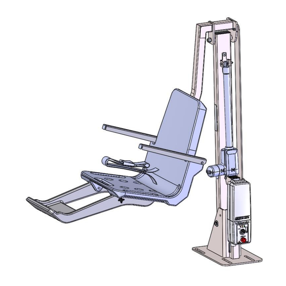
multiLift2 AQUATIC LIFT SYSTEM PRODUCT OVERVIEW The multiLift2 Aquatic Lift is a fixed lift system designed so that individuals with disabilities and mobility impairments can have access to residential, hospitality and multi-unit facility swimming pools or spas. The multiLift2 is powered by a 24-volt rechargeable battery operated by a screw driven electronic actuator that provides the lifting and lowering motions. -
Page 7: Component Description
The armrests are designed for support when transferring onto the seat. They can be rotated up out of the way during transfer. The lift seat assembly is designed to be used exclusively with S.R.Smith aquatic access lifts. Footrest- The footrest is constructed of roto-molded plastic and is easily removable. - Page 8 Emergency Stop Button – In the event of an emergency, or if you need to stop lift movement immediately, pressing the Emergency Stop Button (red button on the control) will stop all lift movement. At the same time an audible alert will sound for 10 sec.
- Page 9 Battery Pack - The battery pack is located on top of the Control Box and is removable. To remove - pull the battery pack away from the mounting plate so that the latch on the battery pack clears the side tabs on the mounting plate - then lift the battery pack up and away from the Control Box. To replace - align the battery pack with the mounting plate so that the latch will drop over the center tab and that the bottom of the battery pack will fit in the recessed area on top of the Control Box.
- Page 10 It is not necessary to fully discharge the battery prior to charging. Battery should be charged daily and cannot be overcharged. It takes up to twelve hours to fully charge depending upon battery usage Do not drop the battery, as it could cause the unit to fail. If the battery case is cracked do not use and replace the battery.
-
Page 11: Unpacking & Assembly Instructions
Prior to opening the shipping container, carefully inspect the external condition of the shipping materials for any visible damage. It is important that any damage be noted on the Bill of Lading prior to signing for the delivery. Contact either S.R.Smith or your dealer immediately to notify us of any damage or missing parts. - Page 12 5. For new anchor installations refer to the instructions starting on page 25. 6. The multiLift2 comes standard with the ability to mount the seat on either side of the lift. Follow assembly instructions starting on page 13 for mounting the seat on the RIGHT side of the lift and page 17 for mounting the seat on the LEFT side of the lift.
- Page 13 RIGHT SIDE SEAT MOUNT CONFIGURATION When standing facing the lift/pool, this is the reference orientation for determining right/left. Caution: During assembly, ensure the lift actuator motor is positioned away from the seat leveling arm. Failure to install the seat leveling arm on the side of the lift opposite to the lift actuator motor will cause interference and damage to the lift components.
- Page 14 7. Install the seat arm to the multiLift2 assembly by using Hardware Kit 580-7100 as shown in Figure 6. 8. Tighten bolt and lock nut until snug; then back off 1/2 rotation. Figure 6 700-9700 7.14.2022...
- Page 15 9. Use Hardware Kit 580-7200 to attach the seat leveling arm to the seat arm as shown in Figure 7. 10. Tighten bolt and lock nut until snug; then back off 1/2 rotation. Figure 7 700-9700 7.14.2022...
- Page 16 11. Next assemble the seat leveling arm to the multiLift2 base as shown in Figure 8. Figure 8 12. Tighten bolt and lock nut until snug; then back off 1/2 rotation. Note: This completes the right mount configuration; please skip to page 21 for the balance of assembly instructions.
- Page 17 LEFT SIDE SEAT MOUNT CONFIGURATION When standing facing the lift/pool, this is the reference orientation for determining right/left. Caution: During assembly, ensure the lift actuator motor is positioned away from the seat leveling arm. Failure to install the seat leveling arm on the side of the lift opposite to the lift actuator motor will cause interference and damage to the lift components.
- Page 18 13. Remove the hardware connecting the actuator to the base. Rotate the actuator 180 degrees so that it is in the position shown in Figure 9 and reattach the actuator. Figure 10 shows the re-assembly sequence for bolt, washer, spacers, and nut. Figure 10 CAUTION: This configuration modification can be challenging, so it’s best (2) two people assist each other to get the spacers back in place and the lift does NOT deploy/move.
- Page 19 14. Install the lift seat arm to the multiLift2 assembly by using Hardware Kit 580-7100 as shown in Figure 11: 15. Tighten bolt and lock nut until snug; then back off 1/2 rotation. Figure 11 700-9700 7.14.2022...
- Page 20 16. Next attach the seat leveling arm to the seat arm as shown in Figure 12. Figure 12 17. Tighten bolt and lock nut until snug; then back off 1/2 rotation. 18. Next assemble the seat leveling to the multiLift2 base as shown in Figure 13. Figure 13 19.
- Page 21 20. Locate Seat Assembly and attach to Seat Frame using bolt (2) Washers, and. (1) Acorn Nut Tighten using (2) ½” Box Wrenches. See Figure 14. Figure 14 21. Attach the Footrest to the Seat using (2) bolts and (2) 4-arm knobs through holes on bottom of Seat and Footrest.
- Page 22 22. Install the LiftOperator Control to the mounting bracket by inserting the tabs on the bottom of the mounting bracket into the slots in the lower backside of the controller. Secure the controller to the bracket by installing the #10-32 X 3/8 screw and tightening with the wrench provided. See Figure 16. 1001494 Figure 16 23.
- Page 23 24. Attach battery to LiftOperator Control Box making sure that the battery latch bracket locks into the slots on the control unit mounting bracket. To remove the battery from the control unit, (1) pull outward on the battery handle until the battery latch bracket clears the slots in the control unit mounting bracket, (2) then pull upward, see Figure 18.
-
Page 24: Pool Deck Installation For The Multilift2
14.5” maximum, see Figure 19. Please contact S.R.Smith with any questions concerning deck anchor placement or to determine if the multiLift2 is the best choice for your installation. -
Page 25: Installing Anchors Into Existing Concrete Deck
• Existing slab shall exhibit no signs of cracking or deterioration. 2. S.R.Smith recommends using Simpson SET epoxy adhesives or equivalent for installation of the deck anchors. Use epoxy adhesives per the manufacturer’s instructions. 3. Use Figure 19 to determine the proper location to install the lift, making certain that the front anchors are located the correct distance from the pool edge 4. - Page 26 6. Clean all dust and debris from the holes. 7. Bond at least one of the flush deck anchors per local codes. Contact your local Authority having jurisdiction for the bonding requirements in your area. A threaded hole for attaching a bonding screw is provided on bottom side of one of the deck anchors.
- Page 27 9. 1-1/2” blocks can be used as spacers between the deck surface and the Anchor Jig to ensure that the tops of the anchors are flush with the deck surface. 10. Fill holes approximately half full of epoxy. 11. Insert deck anchors, making sure that the anchors are flush with the top of the deck. 12.
-
Page 28: Installing Anchor Jig Into New Concrete Deck
INSTALLING ANCHOR JIG INTO NEW CONCRETE DECK 700-9700 7.14.2022... -
Page 29: Using The Multilift2
Follow these guidelines to make sure that your anchor jig is installed properly: 1. Minimum concrete slab requirements for the multiLift2: • Slab dimensions should be at least 42” X 60” X 4”, see Figure 23 above. • Anchors shall be installed at a minimum of 4” or greater from the edge of the slab or expansion joint. -
Page 30: Transferring The User To The Water
TRANSFERRING THE USER TO THE WATER Once the unit is positioned for use, use the following procedure to transfer to the seat and into the water. Only persons healthy enough for water activities should use the multiLift2. Users should consult with their physician to determine if water activities are appropriate for the User: •... -
Page 31: Standard Accessories/Optional Accessories
STANDARD ACCESSORIES/OPTIONAL ACCESSORIES The following items are included with all S.R.Smith pool lift models: • Seat Belt Assembly - Nylon water-resistant belt for added security. • Battery/Charger – 24-volt rechargeable battery. Optional accessories may be purchased for your multiLift2 lift through your Authorized Reseller. The following accessories are available: Console/Battery Cover –... -
Page 32: Trouble Shooting
Hand Control should be replaced. If none of the above steps work in getting the lift to function, call S.R.Smith for assistance. LONG-TERM STORAGE When storing the lift for an extended period of time: •... -
Page 33: Warranty Information
2. Write down or take photo of the serial # sticker from the product. S.R.Smith provides a serial # for every board, lift, stand, slide and rail product we produce. The sticker with the serial number for our boards, stands and slides is a silver, 1" long rectangular sticker found on the side or bottom of the item. -
Page 34: Specifications
SPECIFICATIONS multiLift2 1. Dimensions/Capacity Height 58.4“/148.3cm Overall Length-extended 67.3”/170.9 cm 23”/58.5cm Seat Width Unit Weight-inc. chair 118 lb/ 53.52 kg Unit Weight-w/o chair 88 lb/ 39.9 kg Power 24v DC Battery Life 30 cycles (approx.) Lifting Capacity 350 lb/158.7 kg Anchor Reaction Load: Vertical 467 lb/ 211.8 kg... -
Page 35: Appendix A: Multilift2 Seat W/Footrest (160-9200)
APPENDIX A: multiLift™2 SEAT w/FOOTREST (160-9200) FOOTRESTS ATTACH THE multiLift™2 FOOTREST USING THE THUMBSCREWS AND 2 ¾” LONG HEX BOLT • (800-2042 AND 800-2039) *ARMRESTS (PROVIDED WITH SEAT 160-9200) 700-9700 7.14.2022... -
Page 36: Appendix B: New Construction Jig (500-5000A)
APPENDIX B: New Construction Jig (500-5000A) ITEM NO. PART NUMBER DESCRIPTION MULTILIFT NEW CONSTRUCTION ANCHOR JIG 300-6701 HEX NUT, 1’-8 GALVANIZED STEEL 800-0132 MULTILIFT FLUSH DECK ANCHOR 900-6700 NEW CONSTRUCTION ANCHOR JIG WHEN ASSEMBLING THE FLUSH DECK ANCHORS TO THE NEW CONSTRUCTION JIG, MAKE SURE THAT THE DISTANCE BETWEEN THE TOP SURFACE OF THE JIG AND THE TOP OF EACH ANCHOR IS 2.5”, AS SHOWN IN THE DIAGRAM ABOVE. -
Page 37: Appendix C: Multilift2 Pool Lift (580-0000)
APPENDIX C: MULTILIFT2 POOL LIFT (580-0000) 700-9700 7.14.2022...
Need help?
Do you have a question about the multiLift 2 and is the answer not in the manual?
Questions and answers