Table of Contents
Advertisement
Quick Links
7400 Ultimate Series
End Drive Conveyors
Installation, Maintenance and Parts Manual
DORNER MFG. CORP.
P.O. Box 20 • 975 Cottonwood Ave.
Hartland, WI 53029-0020 USA
851-620 Rev. A
Flat Belt Conveyor
For other service manuals visit our website at:
www.dorner.com/service_manuals.asp
INSIDE THE USA
TEL: 1-800-397-8664
FAX: 1-800-369-2440
OUTSIDE THE USA
TEL: 262-367-7600
FAX: 262-367-5827
Advertisement
Table of Contents

Subscribe to Our Youtube Channel
Related Manuals for Dorner Aqua Pruf 7400 Ultimate Series


Summary of Contents for Dorner Aqua Pruf 7400 Ultimate Series
- Page 1 7400 Ultimate Series End Drive Conveyors Installation, Maintenance and Parts Manual Flat Belt Conveyor DORNER MFG. CORP. INSIDE THE USA OUTSIDE THE USA P.O. Box 20 • 975 Cottonwood Ave. TEL: 1-800-397-8664 TEL: 262-367-7600 Hartland, WI 53029-0020 USA FAX: 1-800-369-2440...
-
Page 2: Table Of Contents
Upon receipt of shipment: • Compare shipment with packing slip. Contact factory Dorner reserves the right to make changes at any time regarding discrepancies. without notice or obligation. • Inspect packages for shipping damage. Contact carrier Dorner has convenient, pre-configured kits of Key Service regarding damage.Accessories may be shipped loose. -
Page 3: Warnings - General Safety
• Failure to comply could result in serious injury. WARNING SEVERE HAZARD! • Dorner cannot control the physical installation and application of conveyors. Taking protective measures is the responsibility of the user. • When conveyors are used in conjunction... -
Page 4: Product Description
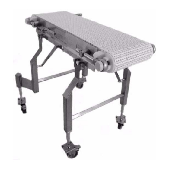
Support Stands Drive End Tension End Figure 1 Specifications Flat Belt 7400 Series Conveyor Cleated Belt 7400 Series Conveyor * Refer to “Ordering and Specifications” Catalog for details. 7400 Ultimate Series End Drive Conveyors Dorner Mfg. Corp. 851-620 Rev. A... -
Page 5: Conveyor Supports
• Non-accumulating product • Product moving toward gearmotor • Conveyor being mounted horizontally • Conveyor being located in a dry environment • Conveyor equipped with standard belt only 7400 Ultimate Series End Drive Conveyors 851-620 Rev. A Dorner Mfg. Corp. -
Page 6: Installation
Install the gearmotor, if applicable. Refer to the “7400 CAUTION Series Drive Package Installation, Maintenance and Parts Manual.” Dorner recommends cleaning all the “food Attach the wear strips. Refer to “Wear Strip Installation” zones” prior to placing conveyor into on page 10. -
Page 7: Tail Assembly Installation
Pull pin (x2) Figure 6 Tip up shaft Slide the bearing shafts (Figure 7, item 1) into the take up blocks (Figure 7, item 2). Key stops (x2) 7400 Ultimate Series End Drive Conveyors 851-620 Rev. A Dorner Mfg. Corp. -
Page 8: Nose Bar Tip Up Tail
(Figure 11, item 2). The rounded end of the key stop should be facing the tail. Figure 13 Slide the tip up shaft (Figure 14, item 1) through the Figure 11 designated slots in the frame. 7400 Ultimate Series End Drive Conveyors Dorner Mfg. Corp. 851-620 Rev. A... - Page 9 (Figure 16, item 2). NOTE Do not insert the pull pins on the tension end of the conveyor until the belt has been installed. Figure 16 7400 Ultimate Series End Drive Conveyors 851-620 Rev. A Dorner Mfg. Corp.
-
Page 10: Lifter Installation
(Figure 20, item 1). Make sure the hooked ends of the lifter bars are facing down when resting against the frame. Attach the lifter handle (Figure 20, item 3) to the belt lift pivot rod. 7400 Ultimate Series End Drive Conveyors Dorner Mfg. Corp. 851-620 Rev. A... -
Page 11: Belt Installation
Extend the tension end to remove excess slack in the belt (Figure 27). Reference figure 32. Figure 24 Wrap the belt around the conveyor, making sure the sprocket teeth have engaged the belt. Figure 27 7400 Ultimate Series End Drive Conveyors 851-620 Rev. A Dorner Mfg. Corp. -
Page 12: Belt Return Installation
Push up on the return shaft (Figure 31, item 1) and slide the notched end of the shaft through the small slot on the opposite side of the frame. Figure 29 7400 Ultimate Series End Drive Conveyors Dorner Mfg. Corp. 851-620 Rev. A... -
Page 13: Conveyors Longer Than 10 Ft (3048 Mm)
O-rings (x8) O-rings. Figure 35 Follow the installation process described in “Conveyors Figure 33 up to 10 ft (3048 mm)” starting on page 6. 7400 Ultimate Series End Drive Conveyors 851-620 Rev. A Dorner Mfg. Corp. -
Page 14: Preventive Maintenance And Adjustment
Exposed moving parts can cause serious injury. Lift up on the belt (Figure 38). Dorner recommends cleaning the inside and the outside of the conveyor on a daily basis. Refer to the following steps to access the inside of the conveyor. -
Page 15: Periodic Cleaning
DO NOT submerge or soak bearing assemblies. This will reduce the life of the bearing. Periodic Cleaning Dorner recommends complete disassembly of the conveyor periodically for thorough cleaning. For conveyor disassembly and reassembly instructions: • Refer to “Conveyor Belt Replacement” on page 16. -
Page 16: Wearstrips And Belt Returns
Exposed moving parts can cause serious injury. NOTE Conveyors with Guides Visit www.dorner.com for complete list of troubleshooting solutions. Remove the pull pins (Figure 41, item 1) that connect the guide (Figure 41, item 2) to the frame. -
Page 17: Standard Belts
1) and slide it out of the frame. Follow steps 1 – 3 in "Standard Belts: Replacing a Section of Belt" on page 17. Remove the belt. 7400 Ultimate Series End Drive Conveyors 851-620 Rev. A Dorner Mfg. Corp. -
Page 18: Specialty Intralox 1100 Series Belts
Replace the old section with a new section of belt. CAUTION DO NOT reuse belt rods that are damaged or show signs of wear. Figure 50 7400 Ultimate Series End Drive Conveyors Dorner Mfg. Corp. 851-620 Rev. A... -
Page 19: Replacing The Entire Belt
Belts: Replacing a Section of Belt" on page page 18. Remove the belt. Replace the damaged or worn belt. Refer to “Belt Installation” on page 11 and “Belt Return Installation” page 12. 7400 Ultimate Series End Drive Conveyors 851-620 Rev. A Dorner Mfg. Corp. -
Page 20: Sprocket And Puck Removal
Refer to “Conveyor Belt Replacement” on page 16. Remove the desired sprocket / puck by following these instructions: • A - Drive Sprocket Removal • B - Idler Puck Removal Figure 56 7400 Ultimate Series End Drive Conveyors Dorner Mfg. Corp. 851-620 Rev. A... -
Page 21: B - Idler Puck Removal
Figure 59 Slide the motor support bracket (Figure 57, item 1) off the drive spindle (Figure 59, item 1). Remove the sprockets (Figure 59, item 2). Figure 62 7400 Ultimate Series End Drive Conveyors 851-620 Rev. A Dorner Mfg. Corp. -
Page 22: Reassembling Tail Assembly
3) and the bearing shaft assemblies (Figure 66, item 1) onto the idler shaft (Figure 66, item 2). Figure 64 Remove the pucks (Figure 64, item 2). Figure 66 7400 Ultimate Series End Drive Conveyors Dorner Mfg. Corp. 851-620 Rev. A... - Page 23 Use a hex wrench (Figure 68, item 1) to tighten the bearing shaft fasteners (Figure 68, item 2) to 54 in•lbs. Check after 24 hours of conveyor use. Figure 68 Attach the bearing covers. Reference figure 61. 7400 Ultimate Series End Drive Conveyors 851-620 Rev. A Dorner Mfg. Corp.
-
Page 24: Drive Tail
(Figure 70, item 3). Position the first sprocket with the notch in the sprocket alignment bar. Figure 72 Install washer (Figure 73, item 1) onto spindle shaft. Figure 70 Figure 73 7400 Ultimate Series End Drive Conveyors Dorner Mfg. Corp. 851-620 Rev. A... - Page 25 12. Attach the bearing covers. Figure 75 10. Attach the guard bar (Figure 76, item 1) to the bearing / motor mount bracket shafts (Figure 76, item 2). 7400 Ultimate Series End Drive Conveyors 851-620 Rev. A Dorner Mfg. Corp.
-
Page 26: Bearing Replacement
When inserting the new bearing, make sure the anti-rotation notch (Figure 79, item 1) on the bearing lines up with the groove inside the housing (Figure 79, item 2). 7400 Ultimate Series End Drive Conveyors Dorner Mfg. Corp. 851-620 Rev. A... -
Page 27: Service Parts
Service Parts Service Parts NOTE For replacement parts other than those shown in this section, contact an authorized Dorner Service Center or the factory. Key Service Parts and Kits are identified by the Performance Parts Kits logo . Dorner recommends keeping these parts on hand. - Page 28 1.00" Pitch Belt (Includes Items 1 through 10) WW = Conveyor width ref: 06 - 36 in 02 increments * When the conveyor is ordered with a Dorner gearmotor mounting package the shaft assembly is replaced with a gearmotor mounting bracket.
-
Page 29: Tip Up Tension End
14) conveyors only) WW = Conveyor width ref: 06 - 36 in 02 increments 501188 Guard Bar 5154WW Guard Bar Shaft 501381 Washer 807-1588 O-Ring 501184 Key Stop 7400 Ultimate Series End Drive Conveyors 851-620 Rev. A Dorner Mfg. Corp. -
Page 30: Nose Bar Tip Up Tension End
74UNBT1S- 1" Nose Bar Tail Kit For Specialty Intralox Belt (Includes Items 1 through 6 and 9) WW = Conveyor width ref: 06 - 36 in 02 increments 7400 Ultimate Series End Drive Conveyors Dorner Mfg. Corp. 851-620 Rev. A... -
Page 31: Conveyor Frame And Extension
O-Ring LLL = Conveyor length ref: 036 - 999 in 001 increments Wear Strip Quantity (Item 2) Conveyor Length (LLL) 036- 133- 253- 373- 493- 613- 733- 853- 7400 Ultimate Series End Drive Conveyors 851-620 Rev. A Dorner Mfg. Corp. -
Page 32: 3" (76 Mm) High Sides
503501-LLLLL Right Hand High Side Guide LLLLL = Guide Length in inches with 2 decimal places. 503601-LLLLL Left Hand High Side Guide Example: Guide Length = 95.25" LLLLL = 09525 501676 Pin Assembly 7400 Ultimate Series End Drive Conveyors Dorner Mfg. Corp. 851-620 Rev. A... -
Page 33: Cleated 1" (25 Mm) Guides
LLLLL = Guide Length in inches with 2 decimal places. 502502-LLLLL 1" Cleated Left Hand Guide Example: Guide Length = 95.25" LLLLL = 09525 (18" - 24" wide conveyors) 7400 Ultimate Series End Drive Conveyors 851-620 Rev. A Dorner Mfg. Corp. -
Page 34: Cleated 3" (76 Mm) Guides
LLLLL = Guide Length in inches with 2 decimal places. 502802-LLLLL 3" Cleated Left Hand Guide Example: Guide Length = 95.25" LLLLL = 09525 (18" - 24" wide conveyors) 7400 Ultimate Series End Drive Conveyors Dorner Mfg. Corp. 851-620 Rev. A... - Page 35 3 Chain Support Kit Item Part Number Description Item Part Number Description 74CR Chain Support Kit ( Includes Item 2) 500196 Cleated Return Shaft 500075 Chain Return Shoe 7400 Ultimate Series End Drive Conveyors 851-620 Rev. A Dorner Mfg. Corp.
-
Page 36: Flat Belt Returns
Determine the length of chain required for the conveyor and round up to the nearest foot length. Order the proper number of chain repair kits (1' long each) for your conveyor. Dorner will ship chain kits that are of a reasonable length fully assembled. -
Page 37: Configuring Conveyor Part Number
MA belt material. each end, and 10 link spacing for cleats. 7400 Ultimate Series End Drive Conveyors 851-620 Rev. A Dorner Mfg. Corp. -
Page 38: Return Policy
A representative will discuss action to be taken on the returned items and provide a Returned Goods Authorization number for reference. There will be a return charge on all new undamaged items returned for credit where Dorner was not at fault. Dorner is not responsible for return freight on such items.
Need help?
Do you have a question about the Aqua Pruf 7400 Ultimate Series and is the answer not in the manual?
Questions and answers