Table of Contents
Advertisement
Quick Links
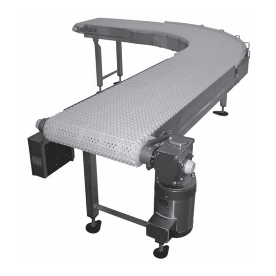
7400 Ultimate Series CE
Curved End Drive Conveyors
Installation, Maintenance and Parts Manual
DORNER MFG. CORP.
P.O. Box 20 • 975 Cottonwood Ave.
Hartland, WI 53029-0020 USA
For other service manuals visit our website at:
851-650 Rev. B
www.dorner.com/service_manuals.asp
INSIDE THE USA
TEL: 1-800-397-8664
FAX: 1-800-369-2440
OUTSIDE THE USA
TEL: 262-367-7600
FAX: 262-367-5827
Advertisement
Table of Contents

Subscribe to Our Youtube Channel
Related Manuals for Dorner AquaPruf Ultimate CE 7400 Series


Summary of Contents for Dorner AquaPruf Ultimate CE 7400 Series
- Page 1 7400 Ultimate Series CE Curved End Drive Conveyors Installation, Maintenance and Parts Manual DORNER MFG. CORP. INSIDE THE USA OUTSIDE THE USA P.O. Box 20 • 975 Cottonwood Ave. TEL: 1-800-397-8664 TEL: 262-367-7600 Hartland, WI 53029-0020 USA FAX: 1-800-369-2440 FAX: 262-367-5827 For other service manuals visit our website at: www.dorner.com/service_manuals.asp...
-
Page 2: Table Of Contents
Upon receipt of shipment: Dorner reserves the right to make changes at any time • Compare shipment with packing slip. Contact factory without notice or obligation. regarding discrepancies. Dorner has convenient, pre-configured kits of Key Service •... -
Page 3: Warnings - General Safety
Loose garments can become caught up in the conveyor. • Failure to comply could result in serious injury. SEVERE HAZARD! • Dorner cannot control the physical WARNING installation and application of conveyors. Taking protective measures is the responsibility of the user. -
Page 4: Product Description
• Non-accumulating product • Product moving toward gearmotor • Conveyor being mounted horizontally • Conveyor being located in a dry environment • Conveyor equipped with standard belt only 7400 Ultimate Series CE Curved End Drive Conveyors 851-650 Rev. B Dorner Mfg. Corp. -
Page 5: Conveyor Supports
Straight Exit / Drive Module 7U WW Module Serialized Sequence: 1 thru 9 Guide Profile Drive Shaft Position Belt Material Stand Location Cleaning Options Drive/ Pulley Type Length Belt Width 7400 Ultimate Series CE Curved End Drive Conveyors 851-650 Rev. B Dorner Mfg. Corp. -
Page 6: Installation
CAUTION Series Drive Package Installation, Maintenance and CAUTION Parts Manual.” Dorner recommends cleaning all the “food Attach the wear strips. Refer to “Wear Strip zones” prior to placing conveyor into service. Installation” on page 11. Ensure adequate access is provided for Attach the belt returns. -
Page 7: Stand Installation
Connect the frame sections by bolting the hex post connectors (Figure 7, item 1) to the cross member supports of each frame section. Figure 9 Figure 7 7400 Ultimate Series CE Curved End Drive Conveyors 851-650 Rev. B Dorner Mfg. Corp. -
Page 8: Tail Assembly Installation
Pull pin (x2) Conveyor frame Figure 13 Figure 11 Slide the bearing shafts (Figure 12, item 1) into the take up blocks (Figure 12, item 2). 7400 Ultimate Series CE Curved End Drive Conveyors Dorner Mfg. Corp. 851-650 Rev. B... -
Page 9: Tip Up Idler Tail
Figure 17 NOTE Do not insert the pull pins on the tension end of the conveyor until the belt has been installed. Figure 15 7400 Ultimate Series CE Curved End Drive Conveyors 851-650 Rev. B Dorner Mfg. Corp. -
Page 10: Nose Bar Tip Up Tail
Figure 21 Attach the nose bar transfer post (Figure 22, item 1) to the nose bar idler shaft hands (Figure 22, item 2). Figure 19 Figure 22 7400 Ultimate Series CE Curved End Drive Conveyors Dorner Mfg. Corp. 851-650 Rev. B... -
Page 11: Lifter Installation
Typical Wear Strip Components (Figure 26) Belt lift pivot bar Wear strip Lifter bars Belt lift handle M8 - 1.25 x 16 mm hex head cap screw Figure 26 Figure 24 7400 Ultimate Series CE Curved End Drive Conveyors 851-650 Rev. B Dorner Mfg. Corp. -
Page 12: Curved Frame Sections
Insert the inside curve top wear strip (Figure 29, item 1) into the innermost slot (Figure 29, item 2) on the inside of the frame. Figure 31 Figure 29 7400 Ultimate Series CE Curved End Drive Conveyors Dorner Mfg. Corp. 851-650 Rev. B... -
Page 13: Belt Return Installation - Curved Frame Sections
Chain belt Belt rod Figure 33 Attach the chain return shoes (Figure 33, item 1) to the curve return shafts (Figure 33, item 2). Figure 35 7400 Ultimate Series CE Curved End Drive Conveyors 851-650 Rev. B Dorner Mfg. Corp. - Page 14 Figure 38 Push the belt rod in as far as possible. Lightly tap the head of the rod with a hammer until it snaps into position. 7400 Ultimate Series CE Curved End Drive Conveyors Dorner Mfg. Corp. 851-650 Rev. B...
-
Page 15: Belt Return Installation - Straight Frame Sections
13 to remove slack from the belt. Up to 102 mm Figure 44 CAUTION CAUTION Belt sag should not exceed 102 mm from the top of the returns. Figure 42 7400 Ultimate Series CE Curved End Drive Conveyors 851-650 Rev. B Dorner Mfg. Corp. -
Page 16: Preventive Maintenance And Adjustment
LOCK OUT POWER before removing guards or performing maintenance. Exposed moving parts can cause serious injury. Dorner recommends cleaning the inside and the outside of the conveyor on a daily basis. Refer to the following steps to access the inside of the conveyor. -
Page 17: Conveyors With Tip Up Tails And Lifters
• Refer to “Belt Return Installation – Straight Frame Sec- tions” on page 15. Periodic Cleaning Maintaining the Conveyor Belt Dorner recommends complete disassembly of the conveyor periodically for thorough cleaning. Troubleshooting For conveyor disassembly and reassembly instructions: NOTE •... -
Page 18: Conveyor Belt Replacement
Replacing a Section of Belt Remove the pull pins (Figure 52, item 1) on the tension end of the conveyor to release tension on the belt. Figure 50 Figure 52 7400 Ultimate Series CE Curved End Drive Conveyors Dorner Mfg. Corp. 851-650 Rev. B... -
Page 19: Replacing The Entire Belt
Replace the old section with a new section of belt. CAUTION CAUTION DO NOT reuse belt rods that are damaged or show signs of wear. Figure 56 7400 Ultimate Series CE Curved End Drive Conveyors 851-650 Rev. B Dorner Mfg. Corp. -
Page 20: Replacing The Entire Belt
(Figure 59, item 2) on the bearing shaft. Figure 58 Lower the opposite end of the return shaft (Figure 58, item 1) and slide it out of the frame. 7400 Ultimate Series CE Curved End Drive Conveyors Dorner Mfg. Corp. 851-650 Rev. B... -
Page 21: Sprocket And Puck Removal
18. Remove the desired sprocket / puck by following these instructions: • A - Drive Sprocket Removal • B - Idler Puck Removal Figure 62 7400 Ultimate Series CE Curved End Drive Conveyors 851-650 Rev. B Dorner Mfg. Corp. -
Page 22: B - Idler Puck Removal
Slide the idler tail assembly (Figure 67, item 1) out of the take up blocks (Figure 67, item 2). Figure 64 Remove the pull pin (Figure 65, item 1). Figure 67 Figure 65 7400 Ultimate Series CE Curved End Drive Conveyors Dorner Mfg. Corp. 851-650 Rev. B... -
Page 23: Reassembling Tail Assembly
(Figure 70, item 3), O-ring (Figure 70, item 4), and flanged puck (Figure 70, item 5) off the idler shaft (Figure 70, item 2). Figure 72 Figure 70 7400 Ultimate Series CE Curved End Drive Conveyors 851-650 Rev. B Dorner Mfg. Corp. -
Page 24: Drive Tail
(Figure 76, item 3). Position the first sprocket with the notch in the sprocket alignment bar. Figure 74 Attach the bearing covers. Figure 76 7400 Ultimate Series CE Curved End Drive Conveyors Dorner Mfg. Corp. 851-650 Rev. B... - Page 25 (Figure 81, item 2). Figure 78 Install washer (Figure 79, item 1) onto spindle shaft. Figure 81 Figure 79 7400 Ultimate Series CE Curved End Drive Conveyors 851-650 Rev. B Dorner Mfg. Corp.
-
Page 26: Bearing Replacement
When inserting the new bearing, make sure the anti-rotation notch (Figure 85, item 1) on the bearing lines up with the groove inside the housing (Figure 85, item 2). 7400 Ultimate Series CE Curved End Drive Conveyors Dorner Mfg. Corp. 851-650 Rev. B... -
Page 27: Notes
NOTES NOTES 7400 Ultimate Series CE Curved End Drive Conveyors 851-650 Rev. B Dorner Mfg. Corp. -
Page 28: Service Parts
Service Parts Service Parts NOTE For replacement parts other than those shown in this section, contact an authorized Dorner Service Center or the factory. Key Service Parts and Kits are identified by the Performance Parts Kits logo . Dorner recommends keeping these parts on hand. - Page 29 (Includes Items 1, 3, 4, 10, 11 and 14) WW = Conveyor width ref: 08 - 36 in 02 increments * When the conveyor is ordered with a Dorner gearmotor mounting package the shaft assembly is replaced with a gearmotor mounting bracket.
-
Page 30: Tip Up Tension End
Guard Bar Shaft Belt (Includes Items 1 through 10, 501381 Washer 13 and 14) 807-1588 O-Ring WW = Conveyor width ref: 08 - 36 in 02 increments 7400 Ultimate Series CE Curved End Drive Conveyors Dorner Mfg. Corp. 851-650 Rev. B... -
Page 31: Nose Bar Tip Up Tension End
1" Nose Bar Tail Kit for Specialty Intralox Belt (Includes Items 1 through 6 and 9) WW = Conveyor width ref: 08 - 36 in 02 increments 7400 Ultimate Series CE Curved End Drive Conveyors 851-650 Rev. B Dorner Mfg. Corp. -
Page 32: Curve Conveyor Frame And Wear Strips
Service Parts Curve Conveyor Frame and Wear Strips 7400 Ultimate Series CE Curved End Drive Conveyors Dorner Mfg. Corp. 851-650 Rev. B... - Page 33 LLLLL = Length in inches with 2 decimal places. Example: Length = 95.25” LLLLL = 09525 WW = Conveyor width ref: 08 - 36 in 02 increments 7400 Ultimate Series CE Curved End Drive Conveyors 851-650 Rev. B Dorner Mfg. Corp.
-
Page 34: Straight Conveyor Frame And Wear Strips
Consult Factory for Frame Part Conveyor Length (LLL) Number 501800-LLL Straight Wear Strip (Refer to chart) LLL = Conveyor length ref: 020 - 999 in 001 increments 7400 Ultimate Series CE Curved End Drive Conveyors Dorner Mfg. Corp. 851-650 Rev. B... -
Page 35: Conveyor Frame Connection
Hex Post Connector 961016MSS Hex Head Cap Screw, M10-1.5x16mm 501494 Hex Head Cap Screw, M10-1.5x16mm 501195 Flat Connector (Not Applicable if Stand Located at Connection) 807-1616 O-Ring 7400 Ultimate Series CE Curved End Drive Conveyors 851-650 Rev. B Dorner Mfg. Corp. -
Page 36: 76 Mm High Sides
LLLLL = Guide Length in inches with 2 decimal places. 503601- Left Hand High Side Guide LLLLL Example: Guide Length = 95.25" LLLLL = 09525 501676 Pin Assembly 7400 Ultimate Series CE Curved End Drive Conveyors Dorner Mfg. Corp. 851-650 Rev. B... -
Page 37: Straight Belt Return
Curve Belt Return Item Part Number Description 5033WW Curve Return Shaft 500075 Chain Return Shoe WW = Conveyor width ref: 08 - 36 in 02 increments 7400 Ultimate Series CE Curved End Drive Conveyors 851-650 Rev. B Dorner Mfg. Corp. -
Page 38: Curve Belt Chain Kit
Determine the length of chain required for the conveyor and round up to the nearest foot length. Order the proper number of chain repair kits (1' long each) for your conveyor. Dorner will ship chain kits that are of a reasonable length fully assembled. -
Page 39: Configuring A Conveyor Part Number
( Curve Module Example: 7U4240901Z1MR4 Straight Infeed / Idler Module Curve module, 24" wide, 90°, ready for Dorner support Example: 7U32412015B1MR1 stands, including frame cutouts and MR belt material. Straight Infeed/Idler module, 24" wide, 10' long, ready for Dorner support stands, first stand 12"... -
Page 40: Return Policy
A representative will discuss action to be taken on the returned items and provide a Returned Goods Authorization number for reference. There will be a return charge on all new undamaged items returned for credit where Dorner was not at fault. Dorner is not responsible for return freight on such items.
Need help?
Do you have a question about the AquaPruf Ultimate CE 7400 Series and is the answer not in the manual?
Questions and answers