Dorner AquaPruf ULTIMATE 7400 Series Installation, Maintenance, And Parts Manual
Hide thumbs
Also See for AquaPruf ULTIMATE 7400 Series:
- Installation manual (66 pages) ,
- Installation, maintenance, and parts manual (46 pages) ,
- Installation, maintenance, and parts manual (42 pages)
Table of Contents
Advertisement
Quick Links
7400 Ultimate Series
End Drive Conveyors
Installation, Maintenance and Parts Manual
DORNER MFG. CORP.
P.O. Box 20 • 975 Cottonwood Ave.
Hartland, WI 53029-0020 USA
851-669 Rev. B
Flat Belt Conveyor
For other service manuals visit our website at:
www.dorner.com/service_manuals.asp
INSIDE THE USA
TEL: 1-800-397-8664
FAX: 1-800-369-2440
OUTSIDE THE USA
TEL: 262-367-7600
FAX: 262-367-5827
Advertisement
Table of Contents

Subscribe to Our Youtube Channel
Related Manuals for Dorner AquaPruf ULTIMATE 7400 Series


Summary of Contents for Dorner AquaPruf ULTIMATE 7400 Series
- Page 1 7400 Ultimate Series End Drive Conveyors Installation, Maintenance and Parts Manual Flat Belt Conveyor DORNER MFG. CORP. INSIDE THE USA OUTSIDE THE USA P.O. Box 20 • 975 Cottonwood Ave. TEL: 1-800-397-8664 TEL: 262-367-7600 Hartland, WI 53029-0020 USA FAX: 1-800-369-2440...
-
Page 2: Table Of Contents
• See accessory instructions for installation. The Dorner Limited Warranty applies. Dorner reserves the right to make changes at any time without notice or obligation. Dorner has convenient, pre-configured kits of Key Service Intralox is a registered trademark of Laitram L.L.C. in the Parts for all conveyor products. -
Page 3: Warnings - General Safety
• Failure to comply could result in serious injury. SEVERE HAZARD! WARNING • Dorner cannot control the physical installation and application of conveyors. Taking protective measures is the responsibility of the user. • When conveyors are used in conjunction... -
Page 4: Product Description
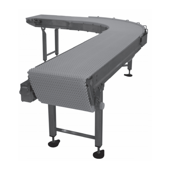
Product Description Refer to (Figure 1) for typical conveyor components. Typical Components Conveyor Belt (Flat Belt Shown) Return Support Stands Drive End Tension End Figure 1 7400 Ultimate Series End Drive Conveyors Dorner Mfg. Corp. 851-669 Rev. B... -
Page 5: Specifications
Specifications Specifications Flat Belt 7400 Series LPZ Conveyor Flat Belt 7400 Series Conveyor Document Language Cleated Belt 7400 Series LPZ Conveyor Cleated Belt 7400 Series Conveyor Document Language 7400 Ultimate Series End Drive Conveyors 851-669 Rev. B Dorner Mfg. Corp. -
Page 6: Conveyor Supports
• Non-accumulating product • Product moving toward gearmotor • Conveyor being mounted horizontally • Conveyor being located in a dry environment • Conveyor equipped with standard belt only 7400 Ultimate Series End Drive Conveyors Dorner Mfg. Corp. 851-669 Rev. B... -
Page 7: Installation
CAUTION Series Drive Package Installation, Maintenance and Parts Manual.” CAUTION Dorner recommends cleaning all the “food Attach the wear strips. Refer to “Wear Strip Installation” zones” prior to placing conveyor into service. on page 13. Ensure adequate access is provided for Install the belt. -
Page 8: Lpz Conveyors
(Figure 7, item 2) with hex rods (Figure 7, item 3) and bolts (Figure 7, item 4). Figure 9 Figure 7 Install wear strips (Figure 7, item 5). 7400 Ultimate Series End Drive Conveyors Dorner Mfg. Corp. 851-669 Rev. B... -
Page 9: Guides
Figure 12 Position the stands on a flat, level surface. Attach the stands to the frame (Figure 13). Figure 11 Figure 13 Tighten hex screws (Figure 13, item 1). 7400 Ultimate Series End Drive Conveyors 851-669 Rev. B Dorner Mfg. Corp. -
Page 10: Tail Assembly Installation
(Figure 15, item 2). Figure 15 Install the drive package, if applicable. Refer to the Figure 17 “7400 Series Drive Package Installation, Maintenance and Parts Manual.” 7400 Ultimate Series End Drive Conveyors Dorner Mfg. Corp. 851-669 Rev. B... - Page 11 Hex shaft assembly will need to be rotated (Figure 20) Conveyor frame for stop keys (Figure 20, item 1) to pass by the frame stops (Figure 20, item 2). Figure 22 7400 Ultimate Series End Drive Conveyors 851-669 Rev. B Dorner Mfg. Corp.
- Page 12 Figure 26 Ensure that the nose bar pucks (Figure 27, item 1) are in line with the conveyor frame (Figure 27, item 2). 180˚ Figure 24 Figure 27 7400 Ultimate Series End Drive Conveyors Dorner Mfg. Corp. 851-669 Rev. B...
-
Page 13: Lifter Installation
(Figure 29, item 1). Make sure the hooked ends of the lifter bars are facing down when resting against the frame. Attach the lifter handle (Figure 29, item 3) to the belt lift pivot rod. 7400 Ultimate Series End Drive Conveyors 851-669 Rev. B Dorner Mfg. Corp. -
Page 14: Belt Installation
Wrap the belt around the conveyor, making sure the Figure 36 sprocket teeth have engaged the belt. CAUTION CAUT ION Belt sag should not exceed 4" (102 mm) from the top of the returns. 7400 Ultimate Series End Drive Conveyors Dorner Mfg. Corp. 851-669 Rev. B... -
Page 15: Belt Return Installation
Slide the return shaft (Figure 39, item 1) up and through the large slot (Figure 39, item 2) in the frame (picture shown without the belt or wear strips). 7400 Ultimate Series End Drive Conveyors 851-669 Rev. B Dorner Mfg. Corp. -
Page 16: Preventive Maintenance And Adjustment
LOCK OUT POWER before removing guards or performing maintenance. Exposed moving parts can cause serious injury. Dorner recommends cleaning the inside and the outside of the conveyor on a daily basis. Refer to the following steps to access the inside of the conveyor. -
Page 17: Conveyors With Tip Up Tails And Lifters
• Refer to “Wear Strip Installation” on page 13. bearing. • Refer to “Belt Return Installation” on page 15. Periodic Cleaning Maintaining the Conveyor Belt Dorner recommends complete disassembly of the conveyor Troubleshooting periodically for thorough cleaning. For conveyor disassembly and reassembly instructions: Inspect conveyor belt for: •... -
Page 18: Conveyor Belt Replacement
Follow the belt replacement procedures described in “Standard Belts” on page 18, “Specialty Intralox 1100 Series Belts” on page 19, or “Specialty Intralox 1600 Series Belts” on page 20. 7400 Ultimate Series End Drive Conveyors Dorner Mfg. Corp. 851-669 Rev. B... -
Page 19: Replacing The Entire Belt
(Figure 51, item 1) and slide it out of the frame. Follow steps 1 – 3 in "Standard Belts: Replacing a Section of Belt" on page 18. Remove the belt. 7400 Ultimate Series End Drive Conveyors 851-669 Rev. B Dorner Mfg. Corp. -
Page 20: Replacing The Entire Belt
Belts: Replacing a Section of Belt" on page page 20. Remove the belt. Figure 55 Replace the damaged or worn belt. Refer to “Belt Installation” on page 14 and “Belt Return Installation” page 15. 7400 Ultimate Series End Drive Conveyors Dorner Mfg. Corp. 851-669 Rev. B... -
Page 21: Conveyor Belt Tensioning
Remove the desired sprocket / puck by following these instructions: • A - Drive Sprocket Removal • B - Idler Puck Removal • C - Nose Bar Puck Removal Figure 59 7400 Ultimate Series End Drive Conveyors 851-669 Rev. B Dorner Mfg. Corp. -
Page 22: B - Idler Puck Removal
(Figure 62, item 1) on the bearing shaft assembly. Figure 63 Slide the idler tail assembly (Figure 63, item 3) out of the tip up hex shaft assembly. 7400 Ultimate Series End Drive Conveyors Dorner Mfg. Corp. 851-669 Rev. B... -
Page 23: C - Nose Bar Puck Removal
(Figure 65, item 2) off the idler shaft (Figure 65, item 3). Figure 67 Slide the nose bar pucks (Figure 67, item 1) off the nose bar shaft (Figure 67, item 2). Figure 65 7400 Ultimate Series End Drive Conveyors 851-669 Rev. B Dorner Mfg. Corp. -
Page 24: Reassembling Tail Assembly
Slide the nose bar pucks (Figure 71, item 1) onto the nose bar drive post (Figure 71, item 2). Figure 69 Install the shaft assembly (Figure 69, item 4). Figure 71 7400 Ultimate Series End Drive Conveyors Dorner Mfg. Corp. 851-669 Rev. B... -
Page 25: Bearing Replacement
• For wearstrips, replace as needed, making sure wear strips are situated securely in the frame slots. • For belt returns, Refer to “Belt Return Installation” on page 15. 7400 Ultimate Series End Drive Conveyors 851-669 Rev. B Dorner Mfg. Corp. -
Page 26: Service Parts
Service Parts Service Parts NOTE For replacement parts other than those shown in this section, contact an authorized Dorner Service Center or the factory. Key Service Parts and Kits are identified by the Performance Parts Kits logo . Dorner recommends keeping these parts on hand. - Page 27 Dorner WW = Conveyor width ref: 06 - 36 in 02 increments Gearmotor Mounting Package * When conveyor is ordered with a Dorner gearmotor for Specialty Intralox 1.00" Pitch mounting package a shaft assembly is replaced with a Belt (Includes Items 1, 3, 6, 7, 9 gearmotor mounting bracket.
-
Page 28: Tip Up Idler End
74UITSX-WW Idler Tail Kit for Specialty Intralox 506396-WW Pinch Guard Shaft Belt (Includes Items 1 through 7) 501489 Pin Assembly WW = Conveyor width ref: 06 - 36 in 02 increments 7400 Ultimate Series End Drive Conveyors Dorner Mfg. Corp. 851-669 Rev. B... -
Page 29: Nose Bar Tip Up Idler End
74UNBT5SX-WW Nose Bar Tail Kit for Specialty 506391-WW Hex Bar Intralox Belt (Includes Items 1 through 5 and 9) WW = Conveyor width ref: 06 - 36 in 02 increments 7400 Ultimate Series End Drive Conveyors 851-669 Rev. B Dorner Mfg. Corp. -
Page 30: Upper Knuckle For 5° - 15
Knuckle Right Hand 18"-24" wide (Includes Items 2 and 7) WW = Conveyor width ref: 06 - 24 in 02 increments AA = Angle 05, 10 or 15 7400 Ultimate Series End Drive Conveyors Dorner Mfg. Corp. 851-669 Rev. B... -
Page 31: Upper Knuckle For 30° - 60
WW = Conveyor width ref: 06 - 24 in 02 increments 501697-AA 1.5" Hold Down Guide for 30° AA = Angle 30, 45 or 60 Knuckle 501879-AA 3" Hold Down Guide for 30° Knuckle 7400 Ultimate Series End Drive Conveyors 851-669 Rev. B Dorner Mfg. Corp. -
Page 32: Lower Knuckle For 5° - 15
1.5" Hold Down Guide for 5° - 15° Knuckle 18"-24" wide 501878-AA 3" Hold Down Guide for 5° - 15° Knuckle 6"-16" wide 501973-AA 3" Hold Down Guide for 5° - 15° Knuckle 18"-24" wide 7400 Ultimate Series End Drive Conveyors Dorner Mfg. Corp. 851-669 Rev. B... -
Page 33: Lower Knuckle For 30° - 60
WW = Conveyor width ref: 06 - 24 in 02 increments 501692-AA 1.5" Hold Down Guide for 30° - 60° AA = Angle 30, 45 or 60 Knuckle 501878-AA 3" Hold Down Guide for 30° - 60° Knuckle 7400 Ultimate Series End Drive Conveyors 851-669 Rev. B Dorner Mfg. Corp. -
Page 34: Conveyor Frame And Extension
Hex Head Cap Screw M10-1.5 x 16mm 807-1616 O-Ring LLL = Conveyor length ref: 036 - 999 in 001 increments WW = Conveyor width ref: 06 - 36 in 02 increments 7400 Ultimate Series End Drive Conveyors Dorner Mfg. Corp. 851-669 Rev. B... -
Page 35: Lifters
Belt Lifter Shaft 501376 Belt Lifter 500491 Belt Lifter Handle 960812MSS Hex Head Cap Screw, M8-1.25 x 12 mm WW = Conveyor width ref: 06 - 60 in 02 increments 7400 Ultimate Series End Drive Conveyors 851-669 Rev. B Dorner Mfg. Corp. -
Page 36: 3" (76 Mm) High Sides
503501-LLLLL Right Hand High Side Guide LLLLL = Guide Length in inches with 2 decimal places. 503601-LLLLL Left Hand High Side Guide Example: Guide Length = 95.25" LLLLL = 09525 501676 Pin Assembly 7400 Ultimate Series End Drive Conveyors Dorner Mfg. Corp. 851-669 Rev. B... -
Page 37: Adjustable Guiding
509875 Mounting Bracket LLLLL = Length in inches with 2 decimal places. 509876 Vertical Post Assembly Length Example: Length = 95.25" LLLLL = 09525 532167-LLLLL Round Guide Rail 7400 Ultimate Series End Drive Conveyors 851-669 Rev. B Dorner Mfg. Corp. -
Page 38: Tool-Less Adjustable Guiding
Eye Bolt M10 x 1.50 mm LLLLL = Length in inches with 2 decimal places. 509875 Mounting Bracket Length Example: Length = 95.25" LLLLL = 09525 509876 Vertical Post Assembly 7400 Ultimate Series End Drive Conveyors Dorner Mfg. Corp. 851-669 Rev. B... -
Page 39: Cleated 1" (25 Mm) Guides
LLLLL = Guide Length in inches with 2 decimal places. 502502-LLLLL 1" Cleated Left Hand Guide Example: Guide Length = 95.25" LLLLL = 09525 (18" - 24" wide conveyors) 7400 Ultimate Series End Drive Conveyors 851-669 Rev. B Dorner Mfg. Corp. -
Page 40: Cleated 3" (76 Mm) Guides
LLLLL = Guide Length in inches with 2 decimal places. 502802-LLLLL 3" Cleated Left Hand Guide Example: Guide Length = 95.25" LLLLL = 09525 (18" - 24" wide conveyors) 7400 Ultimate Series End Drive Conveyors Dorner Mfg. Corp. 851-669 Rev. B... -
Page 41: Returns For Flat Belt Conveyors 26" (660 Mm) Wide And Wider
WW = Conveyor width ref: 26 - 36 in 02 increments Returns for Flat Belt Conveyors up to 24” (610 mm) Wide and Cleated Belt Conveyors Item Part Number Description 532224 Cleated Return Shoe 7400 Ultimate Series End Drive Conveyors 851-669 Rev. B Dorner Mfg. Corp. -
Page 42: Flat Belt
Determine the length of chain required for the conveyor and round up to the nearest foot length. Order the proper number of chain repair kits (1' long each) for your conveyor. Dorner will ship chain kits that are of a reasonable length fully assembled. -
Page 43: Service Parts
10 link spacing for cleats. and MA belt material. 7400 Ultimate Series End Drive Conveyors 851-669 Rev. B Dorner Mfg. Corp. -
Page 44: Return Policy
RMA will automatically close 30 days after being issued. To get credit, items must be new and undamaged. There will be a return charge on all items returned for credit, where Dorner was not at fault. It is the customer’s responsibility to prevent damage during return shipping.
Need help?
Do you have a question about the AquaPruf ULTIMATE 7400 Series and is the answer not in the manual?
Questions and answers