Table of Contents
Advertisement
Quick Links
Advertisement
Table of Contents

Related Manuals for Raisecom Gazelle S2028i


Summary of Contents for Raisecom Gazelle S2028i
- Page 1 Gazelle S2028i (A) Hardware Description...
- Page 2 Website: http://www.raisecom.com Tel: 8610-82883305 Fax: 8610-82883056 Email: export@raisecom.com Address: Raisecom Building, No. 11, East Area, No. 10 Block, East Xibeiwang Road, Haidian District, Beijing, P.R.China Postal code: 100094 ----------------------------------------------------------------------------------------------------------------------------------------- Notice Copyright © 2016 Raisecom All rights reserved.
- Page 3 Preface Objectives This document describes the system structure, power modules, cables, interface parameters, and module parameters of the Layer 2 industrial Ethernet switch Gazelle S2028i. The appendix lists compliant standards and protocols, terms, acronyms, and abbreviations involved in this document.
- Page 4 Terminal display is in Lucida Console. Lucida Console Change history Updates between document versions are cumulative. Therefore, the latest document version contains all updates made to previous versions. Issue 01 (2015-08-15) Initial commercial release Raisecom Proprietary and Confidential Copyright © Raisecom Technology Co., Ltd.
-
Page 5: Table Of Contents
4.1.3 Technical specifications ........................21 4.2 AC power cable .............................. 22 4.2.1 Introduction ............................22 4.2.2 Appearance ............................23 4.2.3 Technical specifications ........................23 4.3 DC power cable .............................. 24 4.3.1 Introduction ............................24 Raisecom Proprietary and Confidential Copyright © Raisecom Technology Co., Ltd. - Page 6 5.2 Service interface module parameters ......................36 5.2.1 1000 Mbit/s optical module ........................36 5.2.2 100 Mbit/s optical module ........................37 6 Appendix ............................39 6.1 Terms ................................39 6.2 Acronyms and abbreviations .......................... 41 Raisecom Proprietary and Confidential Copyright © Raisecom Technology Co., Ltd.
- Page 7 Figure 4-10 LC/PC fiber connector ........................28 Figure 4-11 Serial cable ............................28 Figure 4-12 Wiring of the RS-232 cable ......................29 Figure 4-13 Wiring of the RS-422 cable ......................29 Raisecom Proprietary and Confidential Copyright © Raisecom Technology Co., Ltd.
- Page 8 Raisecom Gazelle ST2028i (A) Hardware Description Figures Figure 4-14 Wiring of the RS-485 cable ......................30 Figure 5-1 Alarm output interface ........................34 Raisecom Proprietary and Confidential Copyright © Raisecom Technology Co., Ltd.
- Page 9 Table 3-1 Specifications of the DC power interface ..................... 18 Table 3-2 Specifications of the AC power interface ..................... 19 Table 3-3 Parameters of the power module ......................19 Table 4-1 Technical specifications of the grounding cable ................... 21 Raisecom Proprietary and Confidential Copyright © Raisecom Technology Co., Ltd.
- Page 10 Table 5-15 Parameters of the 1000 Mbit/s single-fiber bidirectional optical module .......... 37 Table 5-16 Parameters of the 100 Mbit/s dual-fiber bidirectional optical module ..........37 Table 5-17 Parameters of the 100 Mbit/s single-fiber bidirectional optical module ..........38 Raisecom Proprietary and Confidential viii Copyright © Raisecom Technology Co., Ltd.
-
Page 11: Overview
1.1 Introduction The modular network-manageable Layer 2 industrial Ethernet switch Gazelle S2028i (hereinafter referred to as the Gazelle S2028i) adopts a full modular design, thus highly configurable and expansible. Providing various service and functional interfaces which support both the optical and electrical forms, the Gazelle S2028i can well satisfy customers' differentiated requirements. -
Page 12: System Configurations
Gazelle ST2028i (A) Hardware Description 1 Overview 1.2 System configurations Adopting industrial-level chip and power module, the Gazelle S2028i supports configurable interfaces, flexible power supply and networking modes, thus meeting special requirements of on-site industrial environment. Provide density of up to 20+4 interfaces, and support the 0.5U subcard in the upper and ... - Page 13 Raisecom Gazelle ST2028i (A) Hardware Description 1 Overview Parameter Value Alarm interface Maximum switching 250 VAC/220 VDC voltage Maximum switching current Maximum switching 60 W capacity Raisecom Proprietary and Confidential Copyright © Raisecom Technology Co., Ltd.
-
Page 14: Structure
Mapping between interface cards and slots LEDs 2.1 Appearance 2.1.1 Front appearance Figure 2-1 shows the front appearance of the Gazelle S2028i. Figure 2-1 Front appearance LEDs and MODE buttons Interface card slots RJ45 Console interface Raisecom Proprietary and Confidential... -
Page 15: Rear Appearance
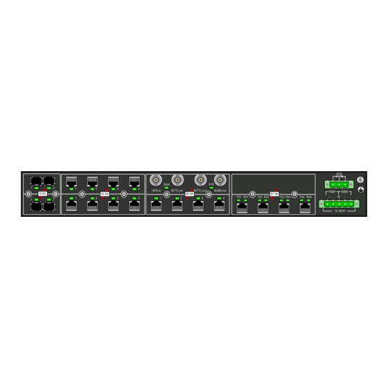
Gazelle ST2028i (A) Hardware Description 2 Structure 2.1.2 Rear appearance Figure 2-2 shows the rear appearance of the Gazelle S2028i. Figure 2-2 Rear appearance Uplink interface card slot 1 (1000 Mbit/s RJ45 interface card and SFP interface card are supported) -
Page 16: Interfaces And Buttons
2.2 Interfaces and buttons Service interfaces The Gazelle S2028i provides up to 4 uplink interfaces, including the 1000 Mbit/s RJ45 electrical interface and SFP optical interface. Moreover, it supports up to 20 downlink interfaces, including the 100 Mbit/s RJ45 electrical interface, 1×9 (SC/PC or ST/PC) optical interface, and SFP optical interface. -
Page 17: Table 2-2 Functional Interfaces
– – PTP card IEEE1588 clock card, no interface on the panel Management and auxiliary interfaces Table 2-3 lists the management and auxiliary interfaces of the Gazelle S2028i. Table 2-3 Management and auxiliary interfaces Interface Print Type Description Console Connected to the terminal through console... -
Page 18: Interface Card
1000 Mbit/s RJ45 interface. Table 2-6 lists LEDs on the 1000 Mbit/s RJ45 interface panel. Table 2-5 Specifications of the 1000 Mbit/s RJ45 interface Interface Type Usage Description S1–S2 RJ45 1000 Mbit/s Ethernet 10/100/1000BASE-T electrical interface Raisecom Proprietary and Confidential Copyright © Raisecom Technology Co., Ltd. -
Page 19: Figure 2-4 1000 Mbit/S Sfp Interface Card
Green: the interface is in Link Up status. Interface Green Blinking green: the interface is sending or status LED receiving data. Off: the interface is in Link Down status. Raisecom Proprietary and Confidential Copyright © Raisecom Technology Co., Ltd. -
Page 20: 100 Mbit/S Downlink Interface Card
The 100 Mbit/s RJ45 interface card provides 4 electrical interfaces. It can be inserted into Slot 3 to Slot 7. The card supports 0.5U subcard in the upper and lower parts. Figure 2-6 shows the 100 Mbit/s SFP interface card. Raisecom Proprietary and Confidential Copyright © Raisecom Technology Co., Ltd. -
Page 21: Figure 2-6 100 Mbit/S Sfp Interface Card
Slot 3 to Slot 7. The card supports 0.5U subcard in the upper and lower parts. Figure 2-7 shows the 100 Mbit/s 1×9 SC/PC interface card. Figure 2-7 100 Mbit/s 1×9 SC/PC interface card Raisecom Proprietary and Confidential Copyright © Raisecom Technology Co., Ltd. -
Page 22: Figure 2-8 100 Mbit/S 1×9 St/Pc Interface Card
Table 2-15 Specifications of the 100 Mbit/s 1×9 ST/PC interface Interface Type Usage Description S1–S4 1×9 ST/PC 100 Mbit/s Ethernet 100BASE-FX: electrical interface TX: transmit data RX: receive data Raisecom Proprietary and Confidential Copyright © Raisecom Technology Co., Ltd. -
Page 23: Serial Interface Card
Off: the interface is not sending data or the serial cable is not connected. 2.3.4 Functional cards Slot 6 to Slot 8 support functional cards. Slot 6 supports GPS card. Slot 8 is reserved for the PTP card only. Raisecom Proprietary and Confidential Copyright © Raisecom Technology Co., Ltd. -
Page 24: Figure 2-10 Gps Card
connector Table 2-20 LEDs on the GPS interface panel Print Status Description Green: the system is working properly. Running status Green Off: the system is not working. Raisecom Proprietary and Confidential Copyright © Raisecom Technology Co., Ltd. -
Page 25: Mapping Between Interface Cards And Slots
1/3/4 as shown in Figure 2-11 refers to interface 4 in slot S3. 2.5 LEDs The LEDs on the Gazelle S2028i are located on the front panel and back panel. And the indication of the corresponding interface status is the same, as listed in Table 2-21. - Page 26 Off: the line is disconnected or improperly connected. When S6, S7 and S8 are configured with functional cards, the corresponding interface status LEDS on the front panel are off. Raisecom Proprietary and Confidential Copyright © Raisecom Technology Co., Ltd.
-
Page 27: Power Modules
Parameters 3.1 Introduction The Gazelle S2028i is embedded with a DC power module or an AC power module. Based on industrial standards, it provides reliable dual power backup and meets strict specifications. The power module has the following functions: The DC power module supports 24/48 VDC input. -
Page 28: Figure 3-1 Dc Power Interface
DC/AC power interfaces are the 7.62 mm × 5-PIN Phoenix terminal. There is one power input interface on the power module of the Gazelle S2028i. Table 3-1 lists specifications of the DC power interface. Table 3-2 lists specifications of the AC power interface. -
Page 29: Parameters
DC power Rated voltage 24/48 VDC Voltage range 20–72 VDC 110/220 VAC AC power Rated voltage 110/220 VDC 85–264 VAC Voltage range 88–300 VDC Frequency 50/60 Hz Raisecom Proprietary and Confidential Copyright © Raisecom Technology Co., Ltd. -
Page 30: Cables
Raisecom Gazelle ST2028i (A) Hardware Description 4 Cables Cables This chapter describes cables for the Gazelle S2028i, including the following sections: Grounding cable AC power cable DC power cable Console cable Fiber Serial cable ... -
Page 31: Technical Specifications
Electronic wire UL1007 or UL1005 is used. Stripped end 10 mm long and plated with tin 3.5/1.75 black heat-shrink tubing. It is a 20 mm plastic tube Insulating sheath which shrinks when being heated. Raisecom Proprietary and Confidential Copyright © Raisecom Technology Co., Ltd. -
Page 32: Ac Power Cable
4.2.1 Introduction The AC power cable supplies 110 V/220 VAC power and 110 V/220 VDC power from the power souring equipment to the power interface of the Gazelle S2028i, and then transmits power to the entire device. The AC power cables of the Gazelle S2028i are different according to local standards. -
Page 33: Appearance
Table 4-4 Specifications of the European standard AC power cable Parameter Description Name POL-AC-French mode 3-pin/unstrapped-0.75mm -1.5m/RoHS French mode three-plug connector Connector 7.62-5PIN-head/RoHS Color Inside Black (PVC insulation) Outside Blue (N), brown (L), green/yellow striped (E) Raisecom Proprietary and Confidential Copyright © Raisecom Technology Co., Ltd. -
Page 34: Dc Power Cable
4.3.1 Introduction The DC power cable supplies 24 V/48 VDC power from the power souring equipment to the power interface of the Gazelle S2028i, and then transmits power to the entire device. 4.3.2 Appearance The DC power cable is composed of Phoenix terminal and power cables, as shown in Figure 4-5. -
Page 35: Technical Specifications
4.4 Console cable 4.4.1 Introduction The RJ45 Console interface can be connected to the Gazelle S2028i and allows you to log in to the Gazelle S2028i. The Console cable is used to connect the Console interface and the RS- 232 serial interface of the maintenance console and transmit configuration data. The maintenance Console implements local debugging and maintenance through the Console interface. -
Page 36: Wiring
Connector RJ45 connector Number of cores Length 4.5 Fiber 4.5.1 Introduction The Gazelle S2028i supports single-mode or multi-mode fiber, as listed in Table 4-8. Table 4-8 Fiber connector Connector Fiber SC/PC 2 mm single-mode fiber Raisecom Proprietary and Confidential... -
Page 37: Appearance
To remove the fiber, push the fiber head inwards, and then pull the fiber out. Figure 4-9 shows the ST/PC fiber connector. Figure 4-9 ST/PC fiber connector Raisecom Proprietary and Confidential Copyright © Raisecom Technology Co., Ltd. -
Page 38: Serial Cable
4.6 Serial cable 4.6.1 Introduction The serial cable is used to connect the RJ45 serial interface of the Gazelle S2028i with its peer device. Through the cable, the status information and data information of the inductor, detector, PLC and intelligent terminal are transmitted to the standard TCP/IP network. -
Page 39: Technical Specifications
– TxD- DATA- Wiring Figure 4-12, Figure 4-13 and Figure 4-14 show the wirings of the RS-232, RS-422 and RS- 485 cable respectively. Figure 4-12 Wiring of the RS-232 cable Raisecom Proprietary and Confidential Copyright © Raisecom Technology Co., Ltd. -
Page 40: Figure 4-13 Wiring Of The Rs-422 Cable
4 Cables Figure 4-13 Wiring of the RS-422 cable Figure 4-14 Wiring of the RS-485 cable The Gazelle S2028i is delivered without the serial cable. If required, make the serial cable on site according to technical specifications. Raisecom Proprietary and Confidential... -
Page 41: Interface And Module Parameters
Raisecom Gazelle ST2028i (A) Hardware Description 5 Interface and module parameters Interface and module parameters This chapter describes interface and module parameters of the Gazelle S2028i, including the following sections: Interface parameters Service interface module parameters 5.1 Interface parameters 5.1.1 Console interface... -
Page 42: Rj45 Electrical Interface
Cat 5 or better UTP cable is recommended. When the interface works under the 1000 Mbit/s mode, the Cat 6 or better UTP cable is recommended. Compliant standard IEEE 802.3 Network protocol Raisecom Proprietary and Confidential Copyright © Raisecom Technology Co., Ltd. -
Page 43: Serial Interface
Baud rate 128 Baud to1 MBaud ≤ 1200 m Transmission Distance The RJ-485 serial interface supports full/half duplex mode. The duplex mode can be configured on the Web interface or CLI. Raisecom Proprietary and Confidential Copyright © Raisecom Technology Co., Ltd. -
Page 44: Alarm Output Interface
Table 5-9 Specifications of the alarm output interface Item Description Connector type 5.08 mm × 3-PIN Phoenix terminal Electrical features Connect/Disconnect Maximum switching voltage 250 VAC/220 V DV Maximum switching current Maximum switching capacity 60 W Raisecom Proprietary and Confidential Copyright © Raisecom Technology Co., Ltd. -
Page 45: B(Am) Output Interface
Table 5-12 lists specifications of the B(TTL) input interface. Table 5-12 Specifications of the B(TTL) input interface Parameter Value Connector type BNC (female) connector 50 Ω Input impedance Electrical features TTL level Raisecom Proprietary and Confidential Copyright © Raisecom Technology Co., Ltd. -
Page 46: Gps Input Interface
Single- USFP- 1310 1260– -10 to -3 mode Gb/S1-I 1620 Single- USFP- 1310 1260– -2 to 3 mode Gb/S2-I 1620 USFP- 1550 1260– 0 to 5 Single- Gb/S3-I 1620 mode Raisecom Proprietary and Confidential Copyright © Raisecom Technology Co., Ltd. -
Page 47: 100 Mbit/S Optical Module
Single- USFP- 1260– 1310 -15 to -8 mode 03/S1-I 1620 Single- USFP- 1310 1260– -5 to 0 mode 03/S2-I 1620 USFP- 1550 1260– -5 to 0 Single- 03/S3-I 1620 mode Raisecom Proprietary and Confidential Copyright © Raisecom Technology Co., Ltd. -
Page 48: Table 5-17 Parameters Of The 100 Mbit/S Single-Fiber Bidirectional Optical Module
Single- USFP- 1550 1260– -15 to -8 mode 03/SS15 1360 Single- USFP- 1310 1500– -5 to 0 mode 03/SS23 1580 USFP- 1550 1270– -5 to 0 Single- 03/SS25 1350 mode Raisecom Proprietary and Confidential Copyright © Raisecom Technology Co., Ltd. -
Page 49: Appendix
Frame Data transmission unit In a communication link, both parties can receive and send data Full duplex concurrently. Raisecom Proprietary and Confidential Copyright © Raisecom Technology Co., Ltd. - Page 50 VLAN Tag are transmitted as data in packets. In synchronization transfer mode, no handshaking signals, able to RS232 communicate with RS232 or RS422 devices point to point, in transparent transmission, with a maximum rate of 19.2 Kbit/s Raisecom Proprietary and Confidential Copyright © Raisecom Technology Co., Ltd.
-
Page 51: Acronyms And Abbreviations
6.2 Acronyms and abbreviations Access Node BPDU Bridge Protocol Data Unit Direct Current Distributed Feed Back DHCP Dynamic Host Configuration Protocol ETSI European Telecommunications Standards Institute Gigabit Ethernet GMRP GARP Multicast Registration Protocol Raisecom Proprietary and Confidential Copyright © Raisecom Technology Co., Ltd. - Page 52 Open Shortest Path First Personal Computer Provider Edge PVST Per-VLAN Spanning Tree Relative Humidity Routing Information Protocol RSTP Rapid Spanning Tree Protocol Small Form-factor Pluggable Surge Protective Device Spanning Tree Protocol Raisecom Proprietary and Confidential Copyright © Raisecom Technology Co., Ltd.
- Page 53 Raisecom Gazelle ST2028i (A) Hardware Description 6 Appendix UART Universal Asynchronous Receiver/Transmitter Underwriter Laboratories VLAN Virtual Local Area Network VLAN Trunk Protocol Raisecom Proprietary and Confidential Copyright © Raisecom Technology Co., Ltd.
- Page 54 Address Raisecom Building, No. 11, East Area, No. 10 Block, East Xibeiwang Road, Haidian District, Beijing, P.R.China. Postal code: 100094 Tel: +86-10-82883305 Fax: 8610-82883056 http://www.raisecom.com Email: export@raisecom.com...
Need help?
Do you have a question about the Gazelle S2028i and is the answer not in the manual?
Questions and answers