
Related Manuals for Panametrics DigitalFlow GS868


Summary of Contents for Panametrics DigitalFlow GS868
- Page 1 Flow DigitalFlow™ GS868 Panametrics Steam Ultrasonic Mass Flowmeter Programming Manual (2-Channel) 910-190P2 E panametrics.com Jul 2021...
- Page 3 Flow DigitalFlow™ GS868 Panametrics Steam Ultrasonic Mass Flowmeter Programming Manual (2-Channel) 910-190P2 E Jul 2021 panametrics.com Copyright 2021 Baker Hughes company. This material contains one or more registered trademarks of Baker Hughes Company and its subsidiaries in one or more countries. All third-party product and company names are trademarks of their respective...
- Page 4 [no content intended for this page]...
- Page 5 Preface Information Paragraphs Note: These paragraphs provide information that provides a deeper understanding of the situation, but is not essential to the proper completion of the instructions. IMPORTANT: These paragraphs provide information emphasizing instructions which are essential to proper setup of the equipment.
- Page 6 Environmental Compliance Waste Electrical and Electronic Equipment (WEEE) Directive Panametrics is an active participant in Europe’s Waste Electrical and Electronic Equipment (WEEE) take-back initiative, directive 2012/19/EU. The equipment that you bought has required the extraction and use of natural resources for its production. It may contain hazardous substances that could impact health and the environment.
-
Page 7: Table Of Contents
Contents Chapter 1. Programming Site Data Introduction ..................... .1 Using the Keypad . - Page 8 Contents Creating an ERROR Log ..................56 3.5.1 Log Type .
- Page 9 Contents Appendix D. Foundation Fieldbus Communications Optional Measurements ..................113 D.10 Configuration Utility Setup .
- Page 10 Contents viii DigitalFlow™ GS868 Programming Manual (2-Channel)
-
Page 11: Chapter 1. Programming Site Data
Chapter 1. Programming Site Data Chapter 1. Programming Site Data Introduction The 2-Channel Model GS868 flowmeter cannot provide accurate flow rate measurements for either channel until the instrument has been properly installed, the channel has been activated, and the basic system and pipe parameters have been programmed into the meter. -
Page 12: Using The Keypad
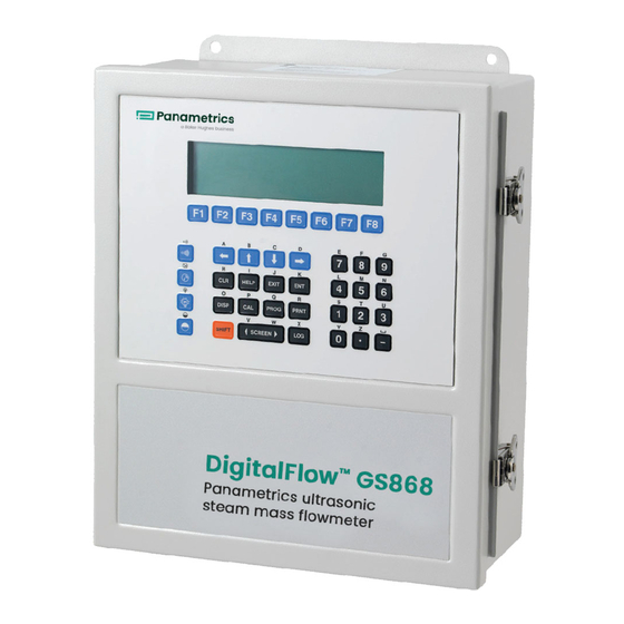
Chapter 1. Programming Site Data Using the Keypad The Model GS868 keypad contains 39 keys, which are labeled with their primary (unshifted) functions. In addition, pressing the red [SHIFT] key will access the secondary functions assigned to most of the keys. The complete keypad is illustrated in Figure 1 below and a detailed description of both the unshifted and shifted functions for each of the 39 keys is listed in Table 1 on page 3. - Page 13 Chapter 1. Programming Site Data Table 1: Model GS868 Key Functions Unshifted Function Shifted Function Software Function Keys - press to None select the functions displayed directly above them in the option bar. These keys apply only to the left pane of the display screen.
- Page 14 Chapter 1. Programming Site Data Table 1: Model GS868 Key Functions(Continued) Unshifted Function Shifted Function Log Key - use to set up logs. See Use to enter the letter X. Chapter 3 for details. Print Key - use to print live Use to enter the letter R.
- Page 15 Chapter 1. Programming Site Data Table 1: Model GS868 Key Functions(Continued) Unshifted Function Shifted Function Five Key - use to enter the number 5. Use to enter the letter M. Six Key - use to enter the number 6. Use to enter the letter N. Seven Key - use to enter the number 7.
-
Page 16: Obtaining On-Line Help
Chapter 1. Programming Site Data Obtaining On-line Help A context-sensitive, on-line help system is programmed into every Model GS868 flowmeter. On-line help, which displays additional information related to the current task, may be accessed at any time by pressing the [HELP] key on the keypad. -
Page 17: Using The Console Control Keys
Chapter 1. Programming Site Data Using the Console Control Keys The Model GS868 has four console control keys located on the left side of the keypad. Use these keys, which are described and pictured in Table 1 on page 3, as follows: 1.4.1 Audio Alarm Volume Use the top console control key to adjust the audio alarm volume. -
Page 18: Entering Programming Mode
Chapter 1. Programming Site Data Programming of the ACTIV, SYSTM (CH1 and GLOBL) and PIPE submenus is necessary for operation of the Model GS868. Failure to accurately enter all of the required information will result in unreliable flow rate data. Therefore, be sure to complete at least the sections of this chapter pertaining to those three submenus. - Page 19 Chapter 1. Programming Site Data Press [F1] (OFF) to deactivate the channel and return to the Channel PROGRAM prompt, or press [F2] to activate the channel in BURST mode. Press [F1] to select Skan mode or [F2] to select Skan/Measure mode. The meter will exit the ACTIV submenu and return to the channel menu screen.
- Page 20 Chapter 1. Programming Site Data Procedure Options After completing the above steps, the meter returns to the Channel PROGRAM prompt. Continue as follows: • To continue programming the meter, refer to the menu maps in Appendix A and navigate to the desired menu. Then, proceed to the appropriate section of this manual for instructions.
-
Page 21: Entering Channel System Data
Chapter 1. Programming Site Data 1.7.2 Entering Channel System Data While following the programming instructions, refer to the menu map in Figure 11 on page 83. IMPORTANT: Do not confuse this SYSTM submenu, which is used to enter channel-specific information, with the SYSTM submenu of the GLOBL menu, which is used to enter information applicable to both channels. - Page 22 Chapter 1. Programming Site Data 1.7.2 Entering Channel System Data (cont.) 10. If Static Density? is set to NO in the ADVAN submenu, go to Procedure Options on the next page. Otherwise, proceed as follows: [F1]-[F4] Use the keys to select the Mass Flow units, listed in Table 3 below. Table 3: Available Mass Flow Units English Mass Flow Units Metric Mass Flow Units...
-
Page 23: Entering Pipe Data
Chapter 1. Programming Site Data 1.7.3 Entering Pipe Data Enter the transducer and pipe parameters via the PIPE submenu. While following the programming instructions, refer to the menu map in Figure 11 on page 83 in Appendix A, Menu Maps . At the Channel Program screen, press [F3] to program the PIPE submenu. -
Page 24: Setting Up Inputs/Outputs
Chapter 1. Programming Site Data Note: The factory has calculated both the transducer signal path length (P) and the transducer signal axial length (L) , based on the exact transducer configuration used for the application. These values are engraved on the flowcell and/or are included in the documentation supplied with the meter. - Page 25 Chapter 1. Programming Site Data 1.7.4.3 Entering the Temperature Input At the Temperature Input prompt, press [F1] to enter a constant temperature value or press [Fx] to select the option card in Slot x that will supply the live temperature input. Each slot that contains an option card with an analog input assigned to TEMP or an RTD input will appear on Note: the option bar.
-
Page 26: Entering Setup Data
Chapter 1. Programming Site Data • To continue programming the meter, refer to the menu maps in Appendix A of the Programming Manual and navigate to the desired menu. Then, proceed to the appropriate section of the manual for instructions. •... - Page 27 Chapter 1. Programming Site Data Press [ENT] to accept the current Soundspeed +– Limit value or enter a new value and press [ENT]. The default value for this parameter is 20% and values from 1% to 50% are acceptable. The E2: SOUNDSPEED error message appears when the calculated fluid soundspeed differs from the fluid soundspeed entered in the SYSTEM menu by more than the programmed SOUNDSPEED +–...
- Page 28 Chapter 1. Programming Site Data Both the upstream and downstream transducers transmit ultrasonic pulses in bursts, which consist of a series of transmit pulses. XMIT SAMPLE SIZE determines how many bursts are sent in one direction before sending in the other direction.
-
Page 29: Setting Advanced Parameters
Chapter 1. Programming Site Data 1.7.5 Setting Signal Limits (cont.) Table 5: Default Values and Limits for SETUP Parameters Parameter Default Value Low Limit High Limit Signal Low Limit Cor. Peak Limit Soundspeed -+ Limit Velocity Low Limit -275.0 ft/sec -500 ft/sec +500 ft/sec (-85 m/sec) - Page 30 Chapter 1. Programming Site Data At the Static Density? prompt, press [F1] = NO or [F2] = YES. If you press NO, the GS868 returns to the ADVAN window. Enter the Fluid Density of the gas to be measured and press [ENT]. (The meter will only accept values from 0.00001-100 lb/ft The GS868 program returns to the ADVAN window.
-
Page 31: Entering Global System Data
Chapter 1. Programming Site Data Entering Global System Data The GLOBL menu is used to enter information that is not specific to one of the individual channels. Information programmed via this menu is used to compute parameters such as the sum, difference or average of the channel 1 and channel 2 signals. -
Page 32: Setting The Clock
Chapter 1. Programming Site Data 1.8.1 Setting the Clock Use the CLOCK submenu to enter the current date and time. While following the programming instructions, refer to the menu map in Figure 13 on page 85. To enter the CLOCK submenu, press [F1] at the Global PROGRAM prompt. 1.8.1.1 Setting the Date The first prompt displays the programmed Date. -
Page 33: Entering Global System Data
Chapter 1. Programming Site Data 1.8.2 Entering Global System Data While following the programming instructions, refer to the menu map in Figure 13 on page 85 . To enter the SYSTEM submenu, press [F2] at the Global PROGRAM prompt. To select the System Units , press [F1] to display parameters and measurements in English units, or press [F2] to display parameters and measurements in Metric units. - Page 34 Chapter 1. Programming Site Data 1.8.2.1 Entering Volumetric Data Use the [F1]-[F4] and ] keys to select the desired Volumetric Units for the flow rate display. The abbreviations and definitions of all the available volumetric and totalizer units are shown in Table 7 below. The choices shown on the option bar are determined by the selection made at the previous SYSTEM UNITS screen.
- Page 35 Chapter 1. Programming Site Data 1.8.2.3 Entering Mass Flow Data If the Static Density? prompt in the ADVAN option (MASS submenu) is set to NO, the meter returns to the GLOBL • prompt. • If Static Density? is set to YES, complete the following steps. 10.
-
Page 36: Setting Up The Inputs And Outputs
Chapter 1. Programming Site Data 1.8.3 Setting Up the Inputs and Outputs While following the programming instructions for the I/O submenu, refer to Figure 14 on page 86. To enter the I/O submenu, press [F3] at the Global PROGRAM prompt. Do one of the following: •... - Page 37 Chapter 1. Programming Site Data 1.8.3.2 Setting Up Input, Output and Option Cards The Model GS868 has two built-in analog outputs, which are assigned to Slot 0. Also, a variety of option cards may be installed in the six expansion slots. See Chapter 1, Installation , of the Startup Guide for a complete description of the available option cards.
- Page 38 Chapter 1. Programming Site Data Setting up Totalizer/Frequency Outputs Press [F1]-[F4] to set up outputs A, B, C or D, respectively. Press [F1] = OFF to disable output A and return to the previous prompt, or press [F2] = FREQ or [F3] = TTLZR to designate output A as a frequency or a totalizer output, respectively.
- Page 39 Chapter 1. Programming Site Data Setting up the RTD Inputs Option cards with RTD inputs have a temperature range of –100° to 350°C. Complete the following steps to set up the two RTD inputs of an option card installed in Slot x: Press [F1] to set up RTD input A or [F2] to set up RTD input B.
-
Page 40: Setting Up Serial Communications
Enter a Network ID number between 1 and 254 and press [ENT]. The default number is 1. A network ID number is only necessary for communication with the Panametrics Instrument Data Manager or PanaView software. See the software User’s Manual for more information. -
Page 41: Modbus Register Map
Chapter 1. Programming Site Data Procedure Options After completing the above steps, the meter returns to the Global PROGRAM prompt. Continue as follows: • To continue programming the meter, refer to the menu maps in Appendix A and navigate to the desired menu. Then, proceed to the appropriate section of this manual for instructions. - Page 42 Chapter 1. Programming Site Data Table 12: MODBUS Registers for a 2-Channel GS868 MODBUS Scaling Reg # Hex Addr Description (decimal places) Size in Bytes 2 (16 bit signed) 1” Clear Ch1 Totalizers” 2 (16 bit signed) 1“ Clear Ch2 Totalizers” Ch1 Velocity 4 (2 16-bit int) Ch1 Act Volumetric...
-
Page 43: Activating Security
Chapter 1. Programming Site Data Table 12: MODBUS Registers for a 2-Channel GS868(Continued) Avg Std Volumetric #Q DIGITS 4 (IEEE 32 bit) Avg Fwd Totals #T DIGITS 4 (2 16 bit int) Avg Rev Totals #T DIGITS 4 (2 16 bit int) Avg #Tot Digits Avg Mass Flow #M DIGITS... - Page 44 Chapter 1. Programming Site Data IMPORTANT: Once the system has been locked, it can only be unlocked by entering the password, because access to the SECUR submenu is restricted. To program the SECUR submenu, press ] and [F1] at the Global PROGRAM prompt. Refer to Figure 13 on page 85. IMPORTANT: It is recommended that all program parameters be recorded before changing the password.
-
Page 45: Saving Site Data
Chapter 1. Programming Site Data 1.8.7 Saving Site Data The currently programmed site data may be stored in the Model GS868’s non-volatile memory by saving it as a site file. Up to ten site file names, consisting of up to five characters each, may be stored at any given time. To enter the SAVE menu, press [F4] at the initial User Program screen. - Page 46 Chapter 1. Programming Site Data [no content intended for this page] DigitalFlow™ GS868 Programming Manual (2-Channel)
-
Page 47: Chapter 2. Displaying Data
Chapter 2. Displaying Data Chapter 2. Displaying Data Introduction This chapter explains how to display measurement data in various formats. Each of the two display screen panes may be programmed independently. The instructions in this chapter assume that the left display pane is active. If the right display pane is active, Note: simply change all [F1]-[F4] designations to [F5]-[F8] . -
Page 48: The Big Format
Chapter 2. Displaying Data The BIG Format The BIG format, which is the Model GS868’s default power up format, displays one measurement in large print. To select the BIG format and the measurement to display in this format, follow the instructions in this section. Upon power up, a standard measurement mode display (similar to the one shown below) appears. -
Page 49: The Dual Format
Chapter 2. Displaying Data The DUAL Format The DUAL format displays two measurements simultaneously in normal print. To select the DUAL format and the measurements to display in this format, follow the instructions in this section. Upon power up, a standard measurement mode display (similar to the one shown below) appears in BIG format. Press the appropriate side of the [SCREEN] key to activate the desired pane of the display screen, and complete the following steps: To access the Display Menu , press the [DISP] key. -
Page 50: Using The Graph Format
Chapter 2. Displaying Data 2.4.2 Using the GRAPH Format While viewing data in the GRAPH format, the function keys are programmed to permit a variety of actions. These options are described in detail below. 1.23 Ft/s 10:16 Use the ] and [F1]-[F4] keys to select the desired option. -
Page 51: The Log Format
Chapter 2. Displaying Data The LOG Format The LOG submenu permits the display of the data in a log file either graphically or numerically. Although the Model GS868 can display all of the data in a log file, screen size limitations prevent the simultaneous display of the complete log file. -
Page 52: Numeric Format
Chapter 2. Displaying Data 2.5.2 Numeric Format The Model GS868 can log up to three parameters simultaneously. Each set of data values is called a record , and up to 120 consecutive records can be stored in a page . A log file can consist of up to 120 pages. The numeric log display, which shows one record at a time, includes the following components: •... - Page 53 Chapter 2. Displaying Data 1.23 Ft/s 10:16 Use the ] and [F1]-[F4] keys to select the desired option. See Table 16 on page 43 for the list of options. ST: 08 MAR 09:50 <CURS CURS> START At any given time, the 120 records stored in one page of the log file will be graphed on the display screen. The cursor , which is shown as a vertical line that extends the full height of the graph window, can be used to highlight any one of these records.
-
Page 54: Displaying The Transducer Signal
Chapter 2. Displaying Data 2.5.3 Graphical Format (cont.) In the typical graphical display shown, the first logged parameter (VEL) is shown to the left of the y-axis and there is a message line below the graph that initially indicates the starting date and time of the current page. Notice that most of the locator bar has been replaced by a status line in standard video that shows the value, units and time of the record at the current cursor location. - Page 55 Chapter 2. Displaying Data Displaying the Transducer Signal (cont.) 686.798mi ] and [F1]-[F4] keys to select the desired option. Use the Options are listed in Table 18 below. ST: 594.298usec <CURS CURS> <PAGE PAGE> The typical display screen shown has the Sup transducer signal listed to the left of the y-axis and there is a message line below the graph that initially indicates the starting date and time of the graphed signal.
- Page 56 Chapter 2. Displaying Data Displaying the Transducer Signal (cont.) In addition to the functions available on the option bar, some of the numeric keys are used to specify which transducer signal is displayed and to scale the resulting graph. Table 19 below lists these functions. Table 19: Numeric Key Functions Function Scroll down the transducer signal list...
-
Page 57: Setting The Lcd Backlight
Chapter 2. Displaying Data Setting the LCD Backlight Use the BACKL submenu to specify the number of minutes the LCD display backlight remains on before it is automatically turned off. Press the appropriate side of the [SCREEN] key to activate the desired pane of the display screen, then proceed as follows: For this discussion, it is assumed that the left pane of the display screen is active. - Page 58 Chapter 2. Displaying Data [no content intended for this page] DigitalFlow™ GS868 Programming Manual (2-Channel)
-
Page 59: Chapter 3. Logging Data
Chapter 3. Logging Data Chapter 3. Logging Data Introduction This chapter explains how to use the Model GS868’s data logging capability. The LOG menu, which is accessed by pressing the [LOG] key on the keypad, is divided into four submenus: •... -
Page 60: Creating A Standard Log
Chapter 3. Logging Data Creating a Standard Log Use the STD submenu to create a new standard log and to select the parameters to log, the log start time and date, the log end time and date, and the time increment. Also, any log file already stored in memory may be inspected and/or changed. -
Page 61: Log Type
Chapter 3. Logging Data Creating a Standard Log (cont.) ] and [F1]-[F4] keys to select the third parameter to be logged. Use the • If you selected a totalized value for display, go to step 8. • If you did not, go to step 9. At the Set Log Totals to 0 prompt, press [F1] to leave the log totals at their present value or press [F2] to reset the log totals to zero. -
Page 62: Start Date Prompt
Chapter 3. Logging Data 3.2.3 START DATE Prompt 11. Press [F1] to accept the displayed Start Date or press [F2] to enter a different start date. To start logging today, press [F3]. • If OK or TODAY was selected, proceed to step 12 for a non-circular log or to step 13 for a circular log. •... -
Page 63: Duration Prompt
Chapter 3. Logging Data 3.2.6 DURATION Prompt If a circular log was specified, the programming sequence continues here after the log start time and/or start date is entered. 14. Press [F1] and enter a log duration in hours or press [F2] and enter a log duration in days. When the desired value has been entered, press [ENT]. -
Page 64: Checking The Memory
Chapter 3. Logging Data Checking the Memory Use the MEM submenu to verify that the available log memory is sufficient for the desired log. If the expected amount of logged data will exceed the remaining memory capacity, the Model GS868 suggests that some old logs be cleared to make room for the new log. -
Page 65: Stopping A Log
Chapter 3. Logging Data Stopping a Log Use the STOP submenu to terminate a logging process that is currently active. Press the appropriate side of the [SCREEN] key to activate the desired pane of the display screen, and complete the following steps: To access the Log Menu , press the [LOG] key. - Page 66 Chapter 3. Logging Data Creating an ERROR Log Use the ERROR submenu to create a new error log and to select the logging parameters. An error log updates every 5 seconds (when the display updates), but only if a new error condition occurs. Error logs have a fixed length of 2 pages and contain sixty records per page.
-
Page 67: Log Type
Chapter 3. Logging Data Creating an ERROR Log (cont.) ] and [F1]-[F4] keys to select the second parameter to be logged. Use the ] and [F1]-[F4] keys to select the third parameter to be logged. Use the •... -
Page 68: Start Date Prompt
Chapter 3. Logging Data 3.5.3 START DATE Prompt 11. Press [F1] to accept the displayed Start Date or press [F2] to enter a different start date. To start logging today, press [F3]. • If OK or TODAY was selected, you have finished setting up the error log. Proceed to Procedure Options below. •... -
Page 69: Chapter 4. Printing Data
Chapter 4. Printing Data Chapter 4. Printing Data Introduction The Model GS868 flowmeter has the capability to print any of the data stored in its memory via the built-in RS232 communications port. In order to use the function, the RS232 port must be connected to a printer with a serial port input. -
Page 70: Print Live Data
Chapter 4. Printing Data Print Live Data Use the DATA submenu to print live measurement data, as it is collected. The data may be printed in either numeric or graphical format, with a user specified time increment. IMPORTANT: Make sure that a printer has been properly set up before proceeding with this section. To print live measurement data, refer to Figure 16 on page 88 , and complete the following steps: To access the Print Menu , press the [PRNT] key. - Page 71 Chapter 4. Printing Data 4.2.1 Numeric Format (cont.) After the time increment is chosen, the Model GS868 returns to the standard data display screen and continues to take measurements. The live data is printed at the specified time intervals, until a STOP command is issued (see the instructions for the STOP submenu).
-
Page 72: Graphical Format
Chapter 4. Printing Data 4.2.2 Graphical Format To print live data in graphical format, continue as follows: ] and [F1]-[F4] keys to select the first parameter to be printed. See Table 24 on page 62 for a list Use the of the available options. -
Page 73: Numeric Format
Chapter 4. Printing Data IMPORTANT: Make sure that a printer has been properly set up before proceeding with this section. To print logged measurement data, refer to Figure 16 on page 88 , and complete the following steps: To access the Print Menu , press the [PRNT] key. Note: The Print Menu is not protected by the security feature and a password is never required to access this menu. - Page 74 Chapter 4. Printing Data SITE NAME SITE MESSAGE START TIME X-AXIS 50 seconds PER-DIV END TIME 03:27:01 PM 03:28:46 PM 20 OCT 97 Y-AXIS MAX 500 ACF/M 20 OCT 97 Figure 6: Typical Graphical Printout DigitalFlow™ GS868 Programming Manual (2-Channel)
-
Page 75: Printing A Site File
Chapter 4. Printing Data Printing a Site File Use the PROG submenu to print the data in a site file that was set up and saved as described in Chapter 1, Programming Site Data . To print a site file, refer to Figure 16 on page 88 and complete the following steps: IMPORTANT: Make sure that a printer has been properly set up before proceeding with this section. -
Page 76: Stopping Printing
Chapter 4. Printing Data Stopping Printing Use the STOP submenu to terminate the printing of live, logged or site data. To stop any active printing activity, see Figure 16 on page 88 , and complete the following steps: IMPORTANT: Make sure that a printer has been properly set up before proceeding with this section. To access the Print Menu , press the [PRNT] key. - Page 77 Chapter 4. Printing Data Press the [F1]-[F3] keys to select the desired Signal Array data to print. To abort the procedure, press the [EXIT] key. Note: The SIGNL option causes the raw signal array data to print, while the CROSS option causes the cross-correlation data to print.
-
Page 78: Printing Rtd Data
Chapter 4. Printing Data Printing RTD Data Use the RTDs submenu to send the numeric point value of a connected RTD device to the RS232 port for display on a terminal or RS232 printer. By viewing the point value of the meter at a given temperature, you can calculate the points at the Set Temperature, and the slope of the RTD input in points/degree. -
Page 79: Chapter 5. Clearing Data
Chapter 5. Clearing Data Chapter 5. Clearing Data Introduction This chapter explains how to purge the Model GS868’s memory of various measurement totals and/or files. The Clear Menu , which is accessed by pressing the [CLR] key on the keypad, is divided into three submenus: •... -
Page 80: Deleting Site Files
Chapter 5. Clearing Data Deleting Site Files Use the SITE submenu to clear site files from the GS868’s memory. Use the [SCREEN] key to activate the desired display pane, and complete the following steps: To access the Clear Menu , press the [CLR] key. If you have activated the security feature (see Chapter 1, Programming Site Data , page 33 for details), enter the [ENT] assigned password and press... -
Page 81: Chapter 6. Serial Communications
The first step is to connect the built-in RS232 port in the GS868 to one of the serial ports (COM1 or COM2) on the personal computer. Table 26 below lists the standard cables available from the factory for this purpose. Table 26: Panametrics Serial Cables Part Number... - Page 82 Chapter 6. Serial Communications Press the [F3] key to select the GLOBL menu. PROGRAM Start PROGRAM previous selection appears here GLOBL SAVE Press the [F4] key to select the COMM submenu. PROGRAM Start Global PROGRAM previous selection appears here CLOCK SYSTM COMM ...
-
Page 83: Setting Up The Terminal Software
Chapter 6. Serial Communications Setting Up the Terminal Software Specific instructions are given in this manual for communicating with personal computers running under either the Windows 3.X or Windows 9X/NT operating systems. Proceed to the appropriate section for detailed set up procedures. -
Page 84: Windows 9X/Nt Systems
Chapter 6. Serial Communications 6.4.2 Windows 9X/NT Systems Windows 9X/NT systems use a program called Hyperterminal to access the serial ports. To set up serial communications with a personal computer running under Windows 95, Windows 98 or Windows NT, make sure the GS868 is powered on and complete the following steps: From the Windows START menu, select PROGRAMS>ACCESSORIES>HYPERTERMINAL>HYPERTERMINAL. -
Page 85: Optional Rs485 Serial Interface
Although the standard RS232 serial interface included with the Model GS868 is adequate for most applications, Panametrics offers an optional RS485 serial interface upgrade for special situations. The Model GS868 is easily modified to provide RS485 communications, and this section describes the wiring and use of the special RS232 to RS485 converter. - Page 86 Chapter 6. Serial Communications Disconnect the main power to the electronics console and open the cover. WARNING! Dangerous voltages exist within the electronics console. Do not perform any wiring operations until the main power to the unit has been disconnected. Remove the clear plastic shroud that covers the electrical connectors.
-
Page 87: Multi-Point Wiring
Chapter 6. Serial Communications 6.5.3 Multi-Point Wiring The standard point-to-point wiring configuration for the serial interface converter may be modified to permit the use of a multi-point wiring arrangement. In a multi-point RS485 system, one flowmeter (the master) is connected to the personal computer, while a number of additional flowmeters (the slaves) are chained together and connected to the master flowmeter. -
Page 88: Setting Up An Ethernet Connection
Chapter 6. Serial Communications 6.5.3.1 Reconfiguring a Serial Interface Converter (cont.) Plastic Case Mounting Screw Screwdriver DB9 Connector Figure 10: Opening the Converter Case Table 28: Switch Assembly Settings Position # Point-To-Point Multi-Point Reassemble the serial interface converter and secure it to the mounting bracket with the two mounting screws. Reinstall the mounting bracket into the electronics enclosure and secure it with the standoff and the grounding screw. - Page 89 Chapter 6. Serial Communications To establish Ethernet communications with the GS868, you must install the Ethernet Device Discovery software utility (available with your modified GS868) on a PC connected to the LAN. Once installed and running, the software displays all Ethernet devices currently connected to the subnet. You can identify the GS868 by its MAC address, supplied as part of customer documentation.
-
Page 90: Setting Up A Modbus/Tcp Connection
Chapter 6. Serial Communications Setting Up a MODBUS/TCP Connection A modified GS868 can use the MODBUS/TCP interface to communicate with an internal network. An optional MODBUS/TCP card with a unique MAC (IP) address (installed only in slots 5 or 6) includes an RJ45 connector. To connect the MODBUS/TCP-enabled GS868 to the network, insert the jack of an RJ45 cable into the RJ45 connector, route the cable through the bottom of the GS868, and wire the other end of the cable to the LAN according to the manufacturer’s instructions. -
Page 91: Appendix A. Menu Maps
Appendix A. Menu Maps DigitalFlow™ GS868 Programming Manual (2-Channel) - Page 92 DigitalFlow™ GS868 Programming Manual (2-Channel)
- Page 93 NOTE: Plain text represents prompt area messages and boxed text represents option bar choices. Fx represent function keys to select option bar choices. PROG PROGRAM status ACTIV SYSTM PIPE SITE LABEL See Figure 12 Site status TRANSDUCER NUMBER TOTALIZER UNITS (English) (Metric) SITE MESSAGE...
- Page 94 PROG PROGRAM status ACTIV SYSTM PIPE SETUP CLOCK COMM SAVE RECLL SECUR See Figure 11 See Figure 11 See Figure 11 See Figure 13 See Figure 13 See Figure 13 See Figure 13 See Figure 13 See Figure 13 ERROR OPTN ZERO ERROR HANDLING...
- Page 95 PROG PROGRAM NOTE: Plain text represents prompt area messages and boxed text represents option bar choices. GLOBL SAVE RECLL Fx represent function keys to select option bar choices. Global PROGRAM CLOCK SYSTM COMM SECUR See Figure 14 SYSTEM UNITS BAUD RATE SITE NAME METRC 1200...
- Page 96 PROG PROGRAM GLOBL SAVE RECLL NOTE: Plain text represents prompt area messages and Global PROGRAM boxed text represents option bar choices. Fx represent function keys to select option bar choices. CLOCK SYSTM COMM SECUR Global I/O ERROR OPTN ERROR HANDLING HOLD HIGH HHIGH...
- Page 97 DISP DISPLAY FORMAT DUAL GRAPH SIGNL BACKL SLEEP NAME LCD SLEEP MODE LOG1 LOG2 LOG3 LOG4 Backlight timeout DISPLAY Site Channel FORMAT PLOT GRAPH VARIABLE Y AXIS MAX Y RANGE Signal to Display* VOLUM MDOT +only +/– Skan Meas TIME INCREMENT (*appears only if S/M mode is active) 5sec 10sec...
- Page 98 PRNT PRNT PRINT PRINT DATA PROG STOP PRNTR SGNLS RTDs DATA FORMAT FORMAT PROG STOP PRNTR SGNLS RTDs FORMAT FORMAT PLOT PLOT PLOT PLOT 1st value printed NAME STOP PRINTING SIGNAL ARRAY 1st value printed NAME STOP PRINTING SIGNAL ARRAY LOG1 LOG2 LOG3...
- Page 99 LOGGING CLEAR LOGGING CLEAR STOP ERROR TOTAL SITE STOP ERROR TOTAL SITE X/120 Pages FREE NAME Total to Clear SITE NAME NAME X/120 Pages FREE NAME Total to Clear SITE NAME NAME Y Pages PENDING Y Pages PENDING LOG1 LOG2 LOG3 LOG4 BOTH...
- Page 100 DigitalFlow™ GS868 Programming Manual (2-Channel)
-
Page 101: Appendix B. Data Records
Appendix B. Data Records Option Cards Installed Whenever an option card is installed in one of the Model GS868’s expansion slots, record the type of card and any additional setup information in the appropriate row of Table 29 below. Table 29: Option Cards Installed Slot # Type of Option Card Additional Setup Information... -
Page 102: Initial Setup Data
Initial Setup Data After the Model GS868 flowmeter has been installed, some initial setup data must be entered via the User Program , prior to operation. Record that information in Table 30 below. Table 30: Initial Setup Data General Information Model # Reference Software Vers. - Page 103 Table 30: Initial Setup Data(Continued) Pipe/Transducer Parameters (CH1/CH2-PIPE) Channel 1 Channel 2 Std. Trans. # Std. Trans. # Spec. Trans. # Spec. Trans. # Spec. Trans. Hz Spec. Trans. Hz Spec. Trans. Tw Spec. Trans. Tw Pipe O.D. Pipe O.D. Pipe Wall Pipe Wall Path Length (P)
- Page 104 [no content intended for this page] DigitalFlow™ GS868 Programming Manual (2-Channel)
-
Page 105: Appendix C. Programming With Panaview
The PanaView™ graphical user interface offers interactive communications between Windows-based PCs and Panametrics instruments compatible with the company’s IDM protocol, such as the GS868 ultrasonic gas flowmeter. PanaView is compatible with 32-bit Windows operating systems such as Windows 98SE, NT 4.0 (with Service Pack 6), 2000, XP and ME. -
Page 106: Setting Up The Communications Port
C.5 Setting Up the Communications Port Use the steps below to establish communications with the GS868. Open the “New Meter Browser” window and expand the network tree. Then, highlight the My Computer(Name) branch by clicking on it. Pull down the “Edit” menu by clicking on it in the menu bar. Click on the “New”... - Page 107 Click on the “Communications Port” option to select it. The Setup Communications screen appears similar to Figure 19 below. Figure 19: Setup Communications Screen Open the Protocol menu (the first of the drop-down menus) and click on IDM. Open the COM Port Type menu and click on the desired type (or on TCP/IP , if the GS868 is using an Ethernet con- nection).
-
Page 108: Setting Up Ethernet Communications
C.5.1 Setting up Ethernet Communications If you have selected TCP/IP in step 6 on the previous page, the Setup Communications window appears similar to Figure 20 below. Figure 20: Setup Communications for TCP/IP Type in the desired Name and Timeout (in milliseconds). In the IP Address text box, enter the IP address. -
Page 109: Adding The Gs868
C.6 Adding the GS868 To add the GS868 on the IDM-configured communications port, complete the following steps: Highlight the communication port to which the meter will be added by clicking on it, and then open the “Edit” menu on the menu bar (if the communication port is not highlighted first, the “New Meter” option is not active in the “Edit”... -
Page 110: Editing Meter Properties
Figure 23: The Updated Network Tree The model number and version that appear will vary with your particular meter and software version. Note: However, if the settings do not match, or there is some other difficulty, a screen appears similar to Figure 24 below. Figure 24: Communication Error Screen The screen offers the options of trying again or of canceling the operation. - Page 111 To edit the properties of your GS868: Highlight the meter (as shown in Figure 23 on page 100). Open the “Edit” menu and select the “Properties” option, as shown in Figure 25 below. Figure 25: The Properties Option in the Edit Menu The window appears similar to Figure 26 below.
- Page 112 Figure 26: Properties Window for IDM-Based Meter Note: For illustration purposes, the meter shown here is a one-channel GX868 flowmeter. Specific parameters will vary with your particular meter. DigitalFlow™ GS868 Programming Manual (2-Channel)
-
Page 113: Setting The Meter Clock
C.7.1 Setting the Meter Clock The meter’s Time may be reset in three different ways: • manually enter the time and date in the text box, or • click on the [Sync to PC] option button to have PanaView set the time and date to the current PC setting, or •... -
Page 114: Reading Transducer Signals
C.7.2 Reading Transducer Signals To read a Signal from the meter: Click on the Read Signals button. (If the meter is a multi-channel instrument, open the Channel drop-down menu and click on the desired channel.) After a moment, the Properties window appears similar to Figure 28 below. Figure 28: Active Signal Options To select a different signal type, open the signal menu at the right (shown here with Raw Upstream highlighted) and click on the desired signal. -
Page 115: Clearing Totalizers
Figure 30: Save As Window C.7.5 Clearing Totalizers To clear the meter totalizers, click on the Clear Totalizers button in the Properties window. The meter totalizers are reset to 0. DigitalFlow™ GS868 Programming Manual (2-Channel) -
Page 116: Handling Site Files
C.7.6 Handling Site Files To access site files, click on the Site Files button in the Properties window. The Site File Operations window (shown in Figure 31 below) opens. Figure 31: The Site File Operations Window C.7.6a Saving an Existing Site to the Meter To save an existing site to the meter: Select the radio button for Selected and highlight an existing site in the left pane. - Page 117 Figure 33: Site Name Entry Window The Site File Selection window (Figure 32 on page 106) opens. Highlight a site with the desired settings, and click [Open] PanaView saves the site in the meter with the new name and the desired settings. C.7.6c Saving a Site to the PC To save a site to the PC:...
- Page 118 C.7.6e Saving a Site in Text Form To store the data from a site file as a text file for display or printout: Highlight the site in the left pane. (See Figure 31 on page 106.) Click Save Site Print to PC . The Site File Selection window (shown in Figure 32 on page 106) opens.
-
Page 119: Changing Meter Settings
C.8 Changing Meter Settings Through PanaView, GS868 users can handle remote programming of the meter. They can: • Program and change a meter’s operating parameters; • Set up, start, and stop logs; • Calibrate and test inputs and outputs; • Clear various files. - Page 120 Figure 37: The Site Edit Menu Window Note: The options listed in the left pane correspond to the options available in the GX868 PROGRAM menus. For more information about the options in your instrument program and about appropriate parameters for the GS868, consult the previous chapters in this manual.
- Page 121 Figure 39: Site Edit Menu with Current Settings When you have completed entering parameters in a given option, click [Exit Page] to close the option. You can then double-click on another option, or click [Close] to close the window. You can double-click on another menu to modify its settings, or return to the New Meter Browser. For additional PanaView functions, refer to the PanaView User’s Manual.
- Page 122 [no content intended for this page] DigitalFlow™ GS868 Programming Manual (2-Channel)
-
Page 123: Optional Measurements
Appendix D. Foundation Fieldbus Communications Optional Measurements Foundation Fieldbus provides a means of communicating with the flowmeter. The patent numbers which apply are 5,909,363 and 6,424,872. This Foundation Fieldbus device supports 6 Analog Input (AI) blocks, which can be configured to supply the following measurements on the network (see Table 31 below). -
Page 124: Configuration Utility Setup
D.10 Configuration Utility Setup The following is an example setup using National Instruments Configuration Utility v3.1. Figure 40 below shows the Configuration Utility with a flowmeter on the network (Panametrics Flow-XMT). Figure 40: Configuration Utility Setup Example Note: The following procedures assume that the device has been placed in the OOS (out-of-service) mode before executing. - Page 125 D.11 Selecting the Desired Measurements (cont.) After the desired measurements have been selected for the PRIMARY and SECONDARY SELECTOR, choose the unit system (UNIT_SELECTOR above the PRIMARY_SELECTOR) that has been programmed in the flowmeter (English or SI). Figure 41: Primary Selector Drop Down List DigitalFlow™...
-
Page 126: Selecting Units For Ai Blocks
D.12 Selecting Units for AI Blocks To select the units for the individual AI blocks: Double click on the AI block for which you wish to set the units (ANALOG_INPUT_1 or ANALOG_INPUT_2 in the tree under GEFlow-XMT; see Figure 40 on page 114). Select the Scaling tab and set the unit for the measurement based on the flowmeter settings. -
Page 127: Resetting Instrument Totalizers
D.13 Resetting Instrument Totalizers To reset the instrument totalizers: Double click on the FLOW transducer block (in the tree under GEFlow-XMT; see Figure 40 on page 114). Select the Others tab and scroll down to the CLEAR_TOTALIZERS listing. Select Clear from the drop down list box (see Figure 43 below). After the totals have been reset, select Normal from the drop down list box to resume total accumulation. -
Page 128: Function Block Application
D.14 Function Block Application Figure 44 below is an example setup using the Function Block Application editor. The flowmeter AI blocks, along with the AO and PID of another device on the network, are displayed. We have connected the AI_1 OUT of the flowmeter to the CAS IN of the AO block. -
Page 129: Appendix E. Foundation Fieldbus Tables
Appendix E. Foundation Fieldbus Tables Table 32: Panametrics Fieldbus Device Capability, XGX868 Family of Meter Types GF868, GS868, GM868, XGF868i, XGM868i, and Model XGS868i 1 --General Is the Device registered at the Fieldbus Foundation (Yes/No) Is the Unit released to production, and if not, when? Is there any special functionality that device supports (e.g., display blocks, diagnostic blocks)? - Page 130 Table 32: Panametrics Fieldbus Device Capability, XGX868 Family of Meter Types(Continued) Methods (list all methods available) none 3- Physical Polarity Sensitive (Yes / No) Yes (Protected from failure if installed incorrectly) Quiescent Current Draw (mA) 10 mA idle / 18 mA max...
- Page 131 Table 32: Panametrics Fieldbus Device Capability, XGX868 Family of Meter Types(Continued) 7 - Transducer Blocks Transducer Blocks based on which latest version of the FF-902 FS 1.4 FF spec Block Type Flow/Display Block Class (Std, Enhanced, Custom) Custom/Custom Does the Device support Methods in the Resource and Transducer Blocks? (If it does, then the functionality will be tested.)
- Page 132 Table 32: Panametrics Fieldbus Device Capability, XGX868 Family of Meter Types(Continued) 1143 - pounds per square inch gauge 1324 - kilogram per hour 1360 - standard cubic feet per minute 1361 - standard cubic feet per hour 1526 - Standard cubic meter (20° 1 atm)
- Page 133 Table 32: Panametrics Fieldbus Device Capability, XGX868 Family of Meter Types(Continued) 1333 - pound per day 1334 - short ton per second 1335 - short ton per minute 1336 - short ton per hour 1337 - short ton per day...
- Page 134 Table 32: Panametrics Fieldbus Device Capability, XGX868 Family of Meter Types(Continued) 34016 - Millions of Standard cubic feet per hour 34017 - Millions of Standard cubic feet per minute 34018 - Millions of Standard cubic feet per second 34019 - Millions of Standard cubic meter per day...
- Page 135 Table 32: Panametrics Fieldbus Device Capability, XGX868 Family of Meter Types(Continued) Channel 2 - “Primary Value”/”Secondary Channel 2 Value” AI Block Units - same as channel 1 DigitalFlow™ GS868 Programming Manual (2-Channel)
- Page 136 [no content intended for this page] DigitalFlow™ GS868 Programming Manual (2-Channel)
- Page 137 Index Displaying Data Abbreviations, Volumetric Units......11, 24 BIG Format ..........38 Display Menu .
- Page 138 Index Keys Password Audio Alarm Volume ........7 Default .
- Page 139 Index SAVE UART Bits Menu ........... 35 Available Options.
- Page 140 Index DigitalFlow™ GS868 Programming Manual (2-Channel)
- Page 141 Cable glands of an approved flameproof design are required for Ex d rated equipment. These must be installed • according to the manufacturer’s instructions. Where the cable glands are provided by Panametrics, the manufacturer’s instructions, as supplied to Panametrics, will be included in the documentation.
- Page 142 Chapter Special Conditions for Safe Use Consult the manufacturer if dimensional information on any flameproof joint is necessary. Follow the manufacturer’s instructions to reduce the potential of an electrostatic charging hazard. Consult the manufacturer for genuine replacement flange fasteners. M10x35 hexagon socket cap screws of ISO 12.9 DIN912 grade steel (zinc-plated) or better with a minimum yield strength of 135,000 psi are acceptable alternatives.
- Page 143 Chapter PANAMETRICS 1100 Technology Park Drive Billerica, MA 01821 declare under our sole responsibility that the DigitalFlow™ DF8688 Liquid Ultrasonic Flowmeter DigitalFlow™ GC868 Clamp-On Gas Ultrasonic Flowmeter DigitalFlow™ GF868 Flare Gas Mass Ultrasonic Flowmeter DigitalFlow™ GM868 General-Purpose Gas Ultrasonic Flowmeter DigitalFlow™...
- Page 144 Chapter DigitalFlow™ GS868 Programming Manual (2-Channel)
- Page 146 Customer Support Centers U.S.A. The Boston Center 1100 Technology Park Drive Billerica, MA 01821 U.S.A. Tel: 800 833 9438 (toll-free) 978 437 1000 E-mail: sensing@ge.com Ireland Sensing House Shannon Free Zone East Shannon, County Clare Ireland Tel: +353 61 470200 E-mail: gesensingorders@ge.com Copyright 2021 Baker Hughes company.
Need help?
Do you have a question about the DigitalFlow GS868 and is the answer not in the manual?
Questions and answers