Table of Contents
Advertisement
Quick Links
Advertisement
Table of Contents

Subscribe to Our Youtube Channel
Related Manuals for R.V.R. Elettronica SDC2000


Summary of Contents for R.V.R. Elettronica SDC2000
- Page 1 SDC2000 User Manual Manufactured by Italy...
- Page 2 Revision History Date Version Reason Editor 12/04/05 First Version J. Berti SDC2000 - User Manual Version 1.0 © Copyright 2005 R.V.R. Elettronica SpA Via del Fonditore 2/2c - 40138 - Bologna (Italia) Telefono: +39 051 6010506 Fax: +39 051 6011104 Email: info@rvr.it...
-
Page 3: Table Of Contents
5.3.6 Digital Output 5.3.7 Keyboard 5.3.8 Remote GPS 6. Quick Reference - Installation and use 6.1 Preparation 6.2 Installation 6.2.1 Digital Connection 6.2.2 Analogue Connection 6.2.3 SDC2000/SFN Connection 6.3 Use 6.4 Encoder Use 6.5 Normal Operation 6.5.1 Main Menu 6.5.1.1 [vers] 6.5.1.2 [audio] 6.5.1.3... - Page 4 SDC2000 7. RDS Functions 7.1 Introduction 7.2 Description of RDS 7.3 RDS Software 8. Technical Specifications 8.1 Mechanical Specifications 8.2 Electric Specifications Rev. 1.0 - 12/04/05 User Manual...
-
Page 5: Preliminary Instructions
2. Warranty R.V.R. Elettronica SpA Via del Fonditore, 2/2c Any product of R.V.R. Elettronica is covered by a 24 40138 BOLOGNA (twenty-four) month warranty. ITALY Tel. +39 051 6010506 For components like tubes for power amplifiers, the 3. -
Page 6: If Victim Is Responsive
SDC2000 adhered particles of clothing, or apply any salve or ointment. • clear out mouth if necessary and observe for breathing • Treat victim for shock as required. • if not breathing, begin artificial breathing (Figura 2): tilt head, pinch nostrils, make •... -
Page 7: Unpacking
FM stereo broadcasting, it is housed in a 1HE box for 19" rack mount. The SDC2000 generates an MPX (composite stereo) signal that is processed digitally in its analogue form using the Right and Left analogue inputs, the AES/EBU analogue inputs or the optical input;... - Page 8 The machine features an optimised ground distribution system (Audio and chassis ) to avoid ground loops. The SDC2000 design is based on a modular concept: the different functions are performed by modules that are either connected directly (male connector of one module attached to female connector of another module) or through flat cables terminated by connectors.
-
Page 9: External Description
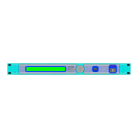
SDC2000 5. External Description This section describes the components found on the front and rear panel of the SDC2000. 5.1 Front Panel DISPLAY Liquid Crystal Display ENCODER Software control knob and button KEYBOARD PS/2 connector for direct connection to PC Keyboard ON/OFF Mains power switch. -
Page 10: Connectors Pinout
SDC2000 5.3 Connectors Pinout 5.3.1 RS 232 Type: Female DB9 TX_D RX_D +12V Note: Normallly, the SDC2000 is configured as DCE (Data Communication Equipment) for serial communication. 5.3.2 Remote Type: DB9 male RDS MS RDS TA RDS TP +3V3 Reserved... -
Page 11: Tos-Link
SDC2000 5.3.5 TOS-LINK Type: TOS-LINK female 5.3.6 Digital Output Type: RCA female In phase (+) Return (-) 5.3.7 Keyboard Type:PS/2 female Data Clock 5.3.8 Remote GPS Type: DB9 female (MPX Digitale Vers.) (/SFN Vers.) Reserved Reserved Reserved OUT.GPS BOARD OK... -
Page 12: Quick Reference - Installation And Use
6.1 Preparation Unpack the SDC2000 and before doing any operation, be sure it has not been damaged during transport. In particular check that all connectors are in perfect condition. -
Page 13: Digital Connection
• Observe the pinouts of the XLR connectors shown in chapter 6. The SDC2000 uses SCA inputs; please refer to chapter 7 for the specifications of these inputs. Connect the mains power cable to the jack on the rear of the machine. -
Page 14: Use
6.5 Normal Operation Switch on the SDC2000 using the switch on the front panel. Upon power-on, DSP initialising information is displayed for a few seconds. On completion, the LCD shows the default screen that provides a graphic display of the... - Page 15 SDC2000 MPX output and Pilot level screen Use the encoder to move within the menu and browse the different SDC2000 input level screens. Turn the knob clockwise to call up the following screens: Right and Left Analogue input levels screen...
-
Page 16: Main Menu
[vers] Push the encoder when this item is blinking to view information about the SDC2000 software release. Displayed information may vary depending on the firmware installed. [audio] Push the encoder when this item is blinking to access a set of submenus where you can edit all parameters of the audio section. -
Page 17: Vers]
6.5.1.1 [vers] Release information window This window shows information on the SDC2000 software release. Displayed information may vary depending on the firmware installed. Push the knob again to go back to the previous menu. 6.5.1.2... - Page 18 SDC2000 If the encoder is pushed when in this submenu, field [BACK] begins to blink and you will be able to move the cursor from field to field by turning the knob in the desired direction. Push the encoder again when a field is selected to confirm that you wish to edit the current selection.
- Page 19 SDC2000 Using the knob, you may cause the right channel, the left channel or both to blink. Push the encoder when the cursor is on one of these items to enable edit mode; the label becomes steady and the value begins to blink. The value displayed in edit mode is the level required to achieve a 0 dBu output level.
- Page 20 SDC2000 a reception phase error condition. When enabled "[Phas]", in the event of an error the system switches to analogue (if allowed). When disabled "[--]", in the event of an error the system will not switch to analogue (if allowed). When an alarm is triggered by a SUB-FRAME phase error, it is reported in field Sts (Sts:[02]).
- Page 21 SDC2000 [BACK] Push the encoder when this item is blinking to cancel selection mode and go back to scrolling through display screens by turning the knob. [Ri=10K] Push the encoder when this item is blinking to select analogue input impedance; you may toggle selection between 10 kOhm and 600Ohm.
- Page 22 SDC2000 Push the encoder when the cursor is on one of these items to enable edit mode; the label becomes steady and the value begins to blink. The value displayed in edit mode is the level required to achieve a 0 dBu output level.
- Page 23 SDC2000 • [Phas] This field enables or disables detection of a reception phase error condition. When enabled “[Phas]”, in the event of an error the system switches to analogue (if allowed). When disabled “[—]”, in the event of an error the system will not switch to analogue (if allowed).
- Page 24 SDC2000 Push the encoder when the cursor is on one of these items to enable edit mode; the label becomes steady and the value begins to blink. The value displayed in edit mode is the level required to achieve a 0 dBu output level.
- Page 25 SDC2000 Please note that in ISOFREQUENCY systems, the reference 19kHz frequency is kept in phase and on frequency by the external or internal GPS systems. In normal equipments, frequency is compliant with applicable standard (19 kHz +/-2Hz). [delay] In this submenu, you may use the knob to set the delay between system inputs and outputs.
- Page 26 SDC2000 [BACK] Push the encoder when this item is blinking to cancel selection mode and go back to scrolling through display screens by turning the knob. [STEREO]Push the encoder when this item is blinking to select MPX signal type; available options are STEREO, MONO L and EXTERN (external).
- Page 27 SDC2000 [A.G.C.] If the encoder is pushed when in this submenu, field [BACK] begins to blink and you will be able to move the cursor from field to field by turning the knob in the desired direction. Push the encoder again when a field is selected to confirm that you wish to edit the current selection.
- Page 28 SDC2000 [I.T.U.] If the encoder is pushed when in this submenu, field [BACK] begins to blink and you will be able to move the cursor from field to field by turning the knob in the desired direction. Push the encoder again when a field is selected to confirm that you wish to edit the current selection.
-
Page 29: Rds]
SDC2000 Push the encoder again when a field is selected to confirm that you wish to edit the current selection. [BACK] Push the encoder when this item is blinking to cancel selection mode and go back to scrolling through display screens by turning the knob. - Page 30 SDC2000 [carr.] If the encoder is pushed when in this submenu, field [BACK] begins to blink and you will be able to move the cursor from field to field by turning the knob in the desired direction. Push the encoder again when a field is selected to confirm that you wish to edit the current selection.
- Page 31 SDC2000 [set-up] In this submenu, you may use the knob to view PSN data settings. Move back to exit the clock setting window; move forward to access edit mode for available parameters. Use the knob to move the cursor to the parameter you wish to edit;...
- Page 32 SDC2000 • NAT[I,JOR,SLO] This field is the code that identifies station country. It is shown in digital format in field PI, with the hexadecimal value ranging from 0 to 15; the figure shows that selection "Italy" is the equivalent of the first hexadecimal character "5"...
- Page 33 SDC2000 • RT[01] This field lets you select one of the radio texts stored in the memory. • F [B] This field lets you select the type of message ("A" or "B"). Radio receivers have a flag that changes status when the message changes, if the message is type B.
-
Page 34: System]
SDC2000 Move back to exit the clock setting window; move forward to access edit mode for available parameters. Use the knob to move the cursor to the parameter you wish to edit; when cursor is on the parameter, push the encoder and edit as required. -
Page 35: Clock]
SDC2000 In this window, you can set and change the password, select baud rate and change menu language. Use the knob to scroll through menu items. When none of the fields is blinking, moving back the knob exits the system window. -
Page 36: Gps] (Only Available Where Option /Sfn Is Installed)
SDC2000 Three indications are available: Time format: hh:mm:tt • absolute time indication Data format: dd-MM-yyyy • current date indication format: [ + 00.00] • difference from Greenwich Mean Time (GMT) in hours. Advance is in half-hour increments; the plus sign means towards EAST, whereas the minus sign means towards WEST. - Page 37 SDC2000 - [Locked -] 19KHz frequency advance lower than 2.5 uSec/ second (minor correction). - [locked +] 19KHz frequency delay lower than 2.5 uSec/ second (minor correction). - [Phase +] 19KHz frequency delay between 2.5 and 5uSec/ second (VCXO correcting).
-
Page 38: Rds Functions
This is how the Radio Data System was established; RDS is now the most widely used data transmission system in radio broadcast. The SDC2000 enables transmission of a data stream in a mono or stereo radio signal as specified in document "Specification of the radio data system (RDS)"... - Page 39 PI (Program Identification) code that enables receiver tuning and identifies the station that is broadcasting the signal. A distinctive feature of the SDC2000 encoder is the ability to support the main services specified by the CENELEC EN50067 standard, namely: PI (discussed above), PS, PTY, TP, AF, TA, DI, M/S, PIN, RT, EON, TDC, IH, CT.
-
Page 40: Rds Software
SDC2000 a) To automatically stop the Tape (or Compact Disk) and switch to Radio; b) To automatically turn on the radio when a traffic announcement begins; c) For automatic switching when tuned station does not broadcast traffic information. M/S - MUSIC/SPEECH SWITCH: Provides independent volume adjustment for music and speech. - Page 41 SDC2000 Software and updates are available for download at the RVR site. For more detailed information, please the manual supplied with the WINRDS software. User Manual Rev. 1.0 - 12/04/05 37 / 40...
-
Page 42: Technical Specifications
SDC2000 8. Technical Specifications 8.1 Mechanical Specifications Panel size 483 mm (19.02”) x 44 mm (1.73”) (1 HE) Depth 407 mm (16.02”) Weight 4 Kg -10 °C ÷ +50 °C Temperature range 8.2 Electric Specifications General AC power supply 100-130 V, 50-60 Hz... - Page 43 SDC2000 Cenelec 50067 Specification (PI: Program Identification, PS: Program Service, PTY: Program Type, TP: Traffic Program Identification, TA: Traffic Announcement, AF: Alternative Frequencies, M/S: Music/Speech, PIN: Program Item Number, RT: Radio Text, EON: Enhanced Other Networks, TDC: Transparent Data Channel, IH: In-house Application) Subcarrier frequency 57 KHz ±1.5 Hz...
- Page 44 SDC2000 This page was intentionally left blank 40 / 40 Rev. 1.0 - 12/04/05 User Manual...
Need help?
Do you have a question about the SDC2000 and is the answer not in the manual?
Questions and answers